EP0277906B1 - Disque en matériau composé pour le rotor d'une soufflante - Google Patents
Disque en matériau composé pour le rotor d'une soufflante Download PDFInfo
- Publication number
- EP0277906B1 EP0277906B1 EP88630016A EP88630016A EP0277906B1 EP 0277906 B1 EP0277906 B1 EP 0277906B1 EP 88630016 A EP88630016 A EP 88630016A EP 88630016 A EP88630016 A EP 88630016A EP 0277906 B1 EP0277906 B1 EP 0277906B1
- Authority
- EP
- European Patent Office
- Prior art keywords
- ring
- plies
- fibers
- assembly according
- generally
- Prior art date
- Legal status (The legal status is an assumption and is not a legal conclusion. Google has not performed a legal analysis and makes no representation as to the accuracy of the status listed.)
- Expired - Lifetime
Links
- 239000002131 composite material Substances 0.000 title claims description 13
- 239000000835 fiber Substances 0.000 claims description 34
- 239000011152 fibreglass Substances 0.000 claims description 6
- 238000004519 manufacturing process Methods 0.000 claims description 5
- OKTJSMMVPCPJKN-UHFFFAOYSA-N Carbon Chemical compound [C] OKTJSMMVPCPJKN-UHFFFAOYSA-N 0.000 claims description 3
- 229910002804 graphite Inorganic materials 0.000 claims description 3
- 239000010439 graphite Substances 0.000 claims description 3
- 238000003754 machining Methods 0.000 claims description 2
- 238000000034 method Methods 0.000 description 5
- 239000011159 matrix material Substances 0.000 description 2
- 125000006850 spacer group Chemical group 0.000 description 2
- 239000013585 weight reducing agent Substances 0.000 description 2
- 238000010276 construction Methods 0.000 description 1
- 230000001419 dependent effect Effects 0.000 description 1
- 238000009434 installation Methods 0.000 description 1
- 230000013011 mating Effects 0.000 description 1
- 239000002184 metal Substances 0.000 description 1
- 238000007789 sealing Methods 0.000 description 1
Images

Classifications
-
- F—MECHANICAL ENGINEERING; LIGHTING; HEATING; WEAPONS; BLASTING
- F01—MACHINES OR ENGINES IN GENERAL; ENGINE PLANTS IN GENERAL; STEAM ENGINES
- F01D—NON-POSITIVE DISPLACEMENT MACHINES OR ENGINES, e.g. STEAM TURBINES
- F01D5/00—Blades; Blade-carrying members; Heating, heat-insulating, cooling or antivibration means on the blades or the members
- F01D5/02—Blade-carrying members, e.g. rotors
-
- F—MECHANICAL ENGINEERING; LIGHTING; HEATING; WEAPONS; BLASTING
- F01—MACHINES OR ENGINES IN GENERAL; ENGINE PLANTS IN GENERAL; STEAM ENGINES
- F01D—NON-POSITIVE DISPLACEMENT MACHINES OR ENGINES, e.g. STEAM TURBINES
- F01D5/00—Blades; Blade-carrying members; Heating, heat-insulating, cooling or antivibration means on the blades or the members
- F01D5/12—Blades
- F01D5/28—Selecting particular materials; Particular measures relating thereto; Measures against erosion or corrosion
- F01D5/282—Selecting composite materials, e.g. blades with reinforcing filaments
-
- F—MECHANICAL ENGINEERING; LIGHTING; HEATING; WEAPONS; BLASTING
- F01—MACHINES OR ENGINES IN GENERAL; ENGINE PLANTS IN GENERAL; STEAM ENGINES
- F01D—NON-POSITIVE DISPLACEMENT MACHINES OR ENGINES, e.g. STEAM TURBINES
- F01D7/00—Rotors with blades adjustable in operation; Control thereof
-
- F—MECHANICAL ENGINEERING; LIGHTING; HEATING; WEAPONS; BLASTING
- F05—INDEXING SCHEMES RELATING TO ENGINES OR PUMPS IN VARIOUS SUBCLASSES OF CLASSES F01-F04
- F05D—INDEXING SCHEME FOR ASPECTS RELATING TO NON-POSITIVE-DISPLACEMENT MACHINES OR ENGINES, GAS-TURBINES OR JET-PROPULSION PLANTS
- F05D2260/00—Function
- F05D2260/70—Adjusting of angle of incidence or attack of rotating blades
- F05D2260/74—Adjusting of angle of incidence or attack of rotating blades by turning around an axis perpendicular the rotor centre line
-
- F—MECHANICAL ENGINEERING; LIGHTING; HEATING; WEAPONS; BLASTING
- F05—INDEXING SCHEMES RELATING TO ENGINES OR PUMPS IN VARIOUS SUBCLASSES OF CLASSES F01-F04
- F05D—INDEXING SCHEME FOR ASPECTS RELATING TO NON-POSITIVE-DISPLACEMENT MACHINES OR ENGINES, GAS-TURBINES OR JET-PROPULSION PLANTS
- F05D2260/00—Function
- F05D2260/70—Adjusting of angle of incidence or attack of rotating blades
- F05D2260/76—Adjusting of angle of incidence or attack of rotating blades the adjusting mechanism using auxiliary power sources
-
- Y—GENERAL TAGGING OF NEW TECHNOLOGICAL DEVELOPMENTS; GENERAL TAGGING OF CROSS-SECTIONAL TECHNOLOGIES SPANNING OVER SEVERAL SECTIONS OF THE IPC; TECHNICAL SUBJECTS COVERED BY FORMER USPC CROSS-REFERENCE ART COLLECTIONS [XRACs] AND DIGESTS
- Y02—TECHNOLOGIES OR APPLICATIONS FOR MITIGATION OR ADAPTATION AGAINST CLIMATE CHANGE
- Y02T—CLIMATE CHANGE MITIGATION TECHNOLOGIES RELATED TO TRANSPORTATION
- Y02T50/00—Aeronautics or air transport
- Y02T50/60—Efficient propulsion technologies, e.g. for aircraft
-
- Y—GENERAL TAGGING OF NEW TECHNOLOGICAL DEVELOPMENTS; GENERAL TAGGING OF CROSS-SECTIONAL TECHNOLOGIES SPANNING OVER SEVERAL SECTIONS OF THE IPC; TECHNICAL SUBJECTS COVERED BY FORMER USPC CROSS-REFERENCE ART COLLECTIONS [XRACs] AND DIGESTS
- Y10—TECHNICAL SUBJECTS COVERED BY FORMER USPC
- Y10T—TECHNICAL SUBJECTS COVERED BY FORMER US CLASSIFICATION
- Y10T428/00—Stock material or miscellaneous articles
- Y10T428/21—Circular sheet or circular blank
- Y10T428/218—Aperture containing
-
- Y—GENERAL TAGGING OF NEW TECHNOLOGICAL DEVELOPMENTS; GENERAL TAGGING OF CROSS-SECTIONAL TECHNOLOGIES SPANNING OVER SEVERAL SECTIONS OF THE IPC; TECHNICAL SUBJECTS COVERED BY FORMER USPC CROSS-REFERENCE ART COLLECTIONS [XRACs] AND DIGESTS
- Y10—TECHNICAL SUBJECTS COVERED BY FORMER USPC
- Y10T—TECHNICAL SUBJECTS COVERED BY FORMER US CLASSIFICATION
- Y10T428/00—Stock material or miscellaneous articles
- Y10T428/24—Structurally defined web or sheet [e.g., overall dimension, etc.]
- Y10T428/24058—Structurally defined web or sheet [e.g., overall dimension, etc.] including grain, strips, or filamentary elements in respective layers or components in angular relation
-
- Y—GENERAL TAGGING OF NEW TECHNOLOGICAL DEVELOPMENTS; GENERAL TAGGING OF CROSS-SECTIONAL TECHNOLOGIES SPANNING OVER SEVERAL SECTIONS OF THE IPC; TECHNICAL SUBJECTS COVERED BY FORMER USPC CROSS-REFERENCE ART COLLECTIONS [XRACs] AND DIGESTS
- Y10—TECHNICAL SUBJECTS COVERED BY FORMER USPC
- Y10T—TECHNICAL SUBJECTS COVERED BY FORMER US CLASSIFICATION
- Y10T428/00—Stock material or miscellaneous articles
- Y10T428/24—Structurally defined web or sheet [e.g., overall dimension, etc.]
- Y10T428/24058—Structurally defined web or sheet [e.g., overall dimension, etc.] including grain, strips, or filamentary elements in respective layers or components in angular relation
- Y10T428/24124—Fibers
Definitions
- This invention relates to a composite disk or ring assembly for supporting the fan blades on a high bypass turbine engine particularly where the fan is mounted outside and surrounding the engine core.
- the invention also concerns a method of making the composite disk or ring assembly.
- disks or rings have been made generally of a metal which is machined to provide the circumferentially spaced bearing mountings in which the individual fan blade roots are supported for turning movement in adjusting the pitch of the blades.
- These metallic rings as disclosed e. g. in US-A-4,021,142 are necessarily heavy in order to carry the loading thereon during the operation of the fan. It is well known that weight reduction is desirable wherever possible in a aircraft engine and if a composite support ring can be made strong enough to carry the loading on the blades a substantial weight reduction will result with an inevitable significant reduction in the total weight of the engine.
- a ring assembly for the support of a row of fan blades for a bypass turbine engine, the blades being turnable on a radial axis for pitch changing, characterized in that said ring assembly comprises a composite ring of layers or plies of fibers, substantially the outer half of the ring having the fibers of the plies thereof generally arranged at 0° to the circumferential direction of the ring, substantially the inner half of the ring having the fibers of a portion of the plies arranged at 0°, said portion of the plies alternating with the remaining plies, said remaining plies comprising in part plies having the fibers thereof at 45° and plies having the fibers thereof at 90 degrees with respect to the circumferential direction of the ring, with additional plies of fibers arranged generally on the side surfaces of the ring and on the inner and outer surfaces and extending beyond the ring to form mounting flanges for the ring, said additional plies having the fibers thereof generally at substantially 45° to the circum
- the method of making the ring assembly is characterized by wrapping the plies making up the inner and outer half of the ring about a support drum, curing the wrapped plies making up the inner and outer half of the ring under heat and pressure, machining the radial openings and the annular groove in the cured ring, applying the additional plies to the side surface and to the inner and outer surfaces of the ring and thereafter curing the additional plies.
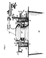
- the ring 10 made of composite material, as will be described later, has the additional plies of fibers 12 on the inner surface 14 and other plies of fibers 16 on the portion of the outer surface 18 to the left of the groove 19 and on one side surface 20.
- the fibers 16 overlap with the plies of fibers 12 to form a flange 24 having an outwardly turned edge to form a radial flange 26 for attachment to a driving ring 27.
- additional plies 28 extending generally radially on the other side surface 30 of the basic ring and projecting radially inward of the ring to overlap with the mating portion 32 of the plies 12 to form the flange 34 for attachment to a support structure 36.
- the ring 10 has radial holes or openings 48 formed therein to receive mounting bosses 50 each of which has a groove 51 in its inner surface to receive a row of ball bearings.
- Each boss has a flange 54 at its inner end and this flange is generally square to provide corners to receive bolts 56 therethrough which extend into the composite ring and hold the bosses in position thereon.
- Suitable spacers 58 are provided to fill the space between the flat flange and the cooperating curved inner surface of the ring to distribute the load on the boss over an extended portion of the ring.
- the ring also has the annular groove 19, above referred to, in its outer surface 18. This groove intersects the holes 48 and exposes the outer ends of the bosses 50.
- the surface 18 is in fact two spaced apart distinct surfaces on opposite sides of the annular groove as mentioned earlier.
- the fan blade 62 has a root 64 with an annular groove 66 thereon positioned in the supporting boss with the bearings 52 engaging said groove 66 as shown.
- the balls are trapped in position by a split clamping ring 68 engaging the outer end of the boss and shoulder 70 on the fan blade root 64 and this arrangement serves to hold the blade root securely in position.
- the ring assembly as above described is supported for rotation in surrounding relation to the engine structure by the support structure 36 extending generally inwardly from the attachment flange 34 and attached thereto.
- the end 73 of the support structure 36 opposite the flange 34 is mounted in a bearing 74 carried by a fixed support structure 76 integral with the surrounding engine casing.
- the blade root has an eccentrically projecting arm 78 at its inner end to provide for the attachment of a pitch control mechanism.
- the composite structure is built up of layers of plies of high strength fiber generally wrapped around a support drum.
- the inner half 10a of the composite ring is made up of about 40% of plies of fibers of graphite filaments arranged at 0° alternating with about 30% of 45° of fiberglass fibers arranged in plies and 30% of 90° fiberglass fibers also arranged in plies.
- the 0° means parallel to the circumferential direction and obviously 90° means the plies are parallel to the longitudinal axis of the ring.
- 45° fibers means at an angle midway between 0° and 90°.
- the remaining outer half 10b of the ring is built up of wrapped layers of plies of graphite fibers all generally at 0° for circumferential strength and stiffness in the completed ring.
- This particular percentage of fibers is characteristic of one specific ring and variations may be utilized depending on the strength desired in certain different portions of the ring. However this particular arrangement has been found to be effective for one particular installation.
- the complete assemblage is cured by the usual curing procedures utilizing heat and pressure.
- the plies may have been pre-pregnated with a matrix material or the matrix material may be added at the start of the curing process. Either of these procedures is well known in the art and the techniques for completing the curing process in either event is also well known.
- the surrounding plies 12 on the inner surface and the plies 16 on the outer surface are positioned.
- the surface 18 is now two spaced surfaces 18 by reason of the intervening groove 19 and the plies do not extend over this groove.
- These plies are generally fiberglass and at 45° so that they may be shaped to conform to the outer surface 18 and the side surface 20 of the ring and also to form the flange 26.
- the plies 28 are mounted at the other side surface 30 of the ring and these plies are also generally fiberglass and with a 45° arrangement of the fibers.
- the other plies 38 are also added and shaped as above described to form the necessary flanges as shown in Fig. 1.
- the ring is again subjected to a curing to harden these additional plies and to form a completed ring or disk construction in which these added plies will be integral with and therefore essentially a part of the basic ring. It is understood that the manner and sequence of assembling the plies may be altered to satisfy individual manufacturing and production capabilities.
Landscapes
- Engineering & Computer Science (AREA)
- Mechanical Engineering (AREA)
- General Engineering & Computer Science (AREA)
- Chemical & Material Sciences (AREA)
- Materials Engineering (AREA)
- Composite Materials (AREA)
- Structures Of Non-Positive Displacement Pumps (AREA)
- Turbine Rotor Nozzle Sealing (AREA)
- Mounting Of Bearings Or Others (AREA)
- Laminated Bodies (AREA)
Claims (8)
- Couronne destinée à supporter une série de pales de soufflante pour un turboréacteur à double flux, ces pales pouvant tourner autour d'un axe radial pour assurer une variation du pas, caractérisée en ce que la couronne est constituée par une couronne composite de couches ou nappes de fibres, les fibres des couches de pratiquement la moitié externe (10b) de la couronne (10) étant disposées d'une manière générale à 0° par rapport à la direction circonférentielle de la couronne (10), les fibres d'une partie des couches de pratiquement la moitié interne (10a) de la couronne (10) étant disposées à 0°, cette partie des couches alternant avec les couches restantes, ces couches restantes comprenant en partie des couches dont les fibres sont orientées à 45° et en partie des couches dont les fibres sont orientées à 90° par rapport à la direction circonférentielle de la couronne (10), des couches additionnelles de fibres (12,16,28,38) étant disposées d'une manière générale sur les surfaces latérales (20,30) de la couronne (10) et sur les surfaces interne et externe (14,18) et s'étendant au-delà de la couronne (10) afin de former des brides de montage (26,34) pour la couronne (10), les fibres de ces couches additionnelles (12,16,28,38) s'étendant d'une manière générale sensiblement à 45° par rapport à la direction circonférentielle de la couronne (10), la couronne composite (10) étant percée trous radiaux (48) pour les pales de soufflante (62), des montures en saillie (50) étant disposées dans les trous (48) afin de recevoir les pieds (64) des pales.
- Couronne suivant la revendication 1 caractérisée en ce que les fibres se trouvant dans la moitié externe (10b) sont généralement en graphite et une partie notable des fibres dans la moitié interne (10a) de la couronne (10) sont des fibres de verre.
- Couronne suivant la revendication 2 caractérisée en ce que les fibres des couches additionnelles (12,16,28,38) sont généralement des fibres de verre.
- Couronne suivant la revendication 1 caractérisée en ce que les montures en saillie (50) sont pourvues de brides (54) situées du côté interne de la couronne (10) et de vis (56) fixant les montures (50) à la couronne (10).
- Couronne suivant la revendication 1 caractérisée en ce qu'une partie des couches additionnelles (38) sont conformées de manière à constituer des brides de joint d'étanchéité (40,42) sur la couronne (10).
- Couronne suivant la revendication 1 caractérisée en ce que les trous radiaux (48) dans la couronne (10) s'étendent à travers la moitié interne (10a) de la couronne (10) et ils débouchent dans une gorge annulaire (19) s'étendant radialement vers l'intérieur à partir de la surface externe (18) de la couronne (10), pour recouper les trous radiaux (48).
- Couronne suivant la revendication 1 caractérisée en ce que dans la moitié interne (10a) de la couronne (10) les fibres d'environ 40% des couches sont disposées avec une orientation à 0°, les fibres d'environ 30% des couches sont disposées à 45° et les fibres des 30% restant des couches sont disposées à 90° par rapport à la direction circonférentielle de la couronne (10).
- Procédé de fabrication de la couronne suivant la revendication 1 caractérisé en ce qu'on enroule les couches formant les moitiés interne et externe (10a,10b) de la couronne (10) autour d'un mandrin support, on durcit les couches enroulées constituant les moitiés interne et externe (10a,10b) de la couronne (10) sous l'effet de la chaleur et de la pression, on usine les trous radiaux (48) et la gorge annulaire (19) dans la couronne durcie, et on applique les couches additionnelles (12,16,28,38) à la surface latérale (20,30) et aux surfaces interne et externe (14,18) de la couronne (10), après quoi on durcit les couches additionnelles (12,16,28,38).
Applications Claiming Priority (2)
| Application Number | Priority Date | Filing Date | Title |
|---|---|---|---|
| US07/010,237 US4717610A (en) | 1987-02-02 | 1987-02-02 | Composite disk for supporting fan blades |
| US10237 | 1993-01-28 |
Publications (3)
| Publication Number | Publication Date |
|---|---|
| EP0277906A2 EP0277906A2 (fr) | 1988-08-10 |
| EP0277906A3 EP0277906A3 (en) | 1990-01-31 |
| EP0277906B1 true EP0277906B1 (fr) | 1992-06-17 |
Family
ID=21744716
Family Applications (1)
| Application Number | Title | Priority Date | Filing Date |
|---|---|---|---|
| EP88630016A Expired - Lifetime EP0277906B1 (fr) | 1987-02-02 | 1988-02-01 | Disque en matériau composé pour le rotor d'une soufflante |
Country Status (4)
| Country | Link |
|---|---|
| US (1) | US4717610A (fr) |
| EP (1) | EP0277906B1 (fr) |
| JP (1) | JP2602682B2 (fr) |
| DE (2) | DE3871973T2 (fr) |
Families Citing this family (8)
| Publication number | Priority date | Publication date | Assignee | Title |
|---|---|---|---|---|
| US5102302A (en) * | 1988-06-02 | 1992-04-07 | General Electric Company | Fan blade mount |
| US5165856A (en) * | 1988-06-02 | 1992-11-24 | General Electric Company | Fan blade mount |
| DE4237031C1 (de) * | 1992-11-03 | 1994-02-10 | Mtu Muenchen Gmbh | Verstellbare Leitschaufel |
| US8794925B2 (en) | 2010-08-24 | 2014-08-05 | United Technologies Corporation | Root region of a blade for a gas turbine engine |
| WO2014186028A1 (fr) * | 2013-05-17 | 2014-11-20 | United Technologies Corporation | Section conique de collet de pied d'aube tangentielle |
| EP3008311A4 (fr) | 2013-06-12 | 2016-07-20 | United Technologies Corp | Collecteur de carburant/d'huile |
| US9869198B2 (en) | 2015-05-13 | 2018-01-16 | General Electric Company | Intershaft integrated seal and lock-nut |
| US9976429B2 (en) | 2015-06-09 | 2018-05-22 | General Electric Company | Composite disk |
Citations (1)
| Publication number | Priority date | Publication date | Assignee | Title |
|---|---|---|---|---|
| US4021142A (en) * | 1974-10-09 | 1977-05-03 | United Technologies Corporation | Pitch-change apparatus for a ducted thrust fan |
Family Cites Families (10)
| Publication number | Priority date | Publication date | Assignee | Title |
|---|---|---|---|---|
| US2802680A (en) * | 1952-05-15 | 1957-08-13 | Kennametal Inc | Turbine wheel assembly |
| AT232635B (de) * | 1962-08-17 | 1964-03-25 | Simmering Graz Pauker Ag | Laufradschaufelbefestigung für eine Axial-Turbomaschine mit Verstellschaufeln |
| FR1494085A (fr) * | 1966-02-01 | 1967-09-08 | Calor App Electro Domestiques | Ventilateur à hélice à pas variable |
| US3532439A (en) * | 1966-11-29 | 1970-10-06 | Rolls Royce | Fibrous reinforced bladed rotor |
| US3622249A (en) * | 1968-08-18 | 1971-11-23 | Aisin Seiki | Fan assembly |
| US3687569A (en) * | 1971-03-19 | 1972-08-29 | Gen Electric | Rotor with variable angle blades |
| FR2143561B1 (fr) * | 1971-06-29 | 1974-03-08 | Snecma | |
| US4045149A (en) * | 1976-02-03 | 1977-08-30 | The United States Of America As Represented By The Administrator Of The National Aeronautics And Space Administration | Platform for a swing root turbomachinery blade |
| US4863352A (en) * | 1984-11-02 | 1989-09-05 | General Electric Company | Blade carrying means |
| JP5938458B2 (ja) | 2014-10-07 | 2016-06-22 | 瀬戸内金網商工株式会社 | 蛇篭連設体 |
-
1987
- 1987-02-02 US US07/010,237 patent/US4717610A/en not_active Expired - Lifetime
-
1988
- 1988-02-01 EP EP88630016A patent/EP0277906B1/fr not_active Expired - Lifetime
- 1988-02-01 DE DE8888630016T patent/DE3871973T2/de not_active Expired - Fee Related
- 1988-02-01 DE DE198888630016T patent/DE277906T1/de active Pending
- 1988-02-02 JP JP63022680A patent/JP2602682B2/ja not_active Expired - Lifetime
Patent Citations (1)
| Publication number | Priority date | Publication date | Assignee | Title |
|---|---|---|---|---|
| US4021142A (en) * | 1974-10-09 | 1977-05-03 | United Technologies Corporation | Pitch-change apparatus for a ducted thrust fan |
Also Published As
| Publication number | Publication date |
|---|---|
| EP0277906A3 (en) | 1990-01-31 |
| JP2602682B2 (ja) | 1997-04-23 |
| DE3871973D1 (de) | 1992-07-23 |
| DE3871973T2 (de) | 1993-02-18 |
| EP0277906A2 (fr) | 1988-08-10 |
| DE277906T1 (de) | 1988-12-15 |
| US4717610A (en) | 1988-01-05 |
| JPS63266131A (ja) | 1988-11-02 |
Similar Documents
| Publication | Publication Date | Title |
|---|---|---|
| US3554668A (en) | Turbomachine rotor | |
| US5470524A (en) | Method for manufacturing a blade ring for drum-shaped rotors of turbomachinery | |
| CA1042348A (fr) | Plateforme pour aube de turbomachinerie | |
| US6213720B1 (en) | High strength composite reinforced turbomachinery disk | |
| US3403844A (en) | Bladed member and method for making | |
| US4063847A (en) | Gas turbine engine casing | |
| US4045149A (en) | Platform for a swing root turbomachinery blade | |
| US4786347A (en) | Method of manufacturing an annular bladed member having an integral shroud | |
| EP1093542B1 (fr) | Structure composite resistante aux chocs pour carter de soufflante de turbine a gaz | |
| EP0757161B1 (fr) | Assemblage des arbes statoriques dans un compresseur de turbine à gaz | |
| US4747900A (en) | Method of manufacture of compressor rotor assembly | |
| CA1164348A (fr) | Organe d'orientation de l'ecoulement pour turbomoteur a gaz | |
| US4646810A (en) | Method for the manufacture of a ceramic turbine ring integral with a metallic annular carrier | |
| US5525035A (en) | Ducted support housing assembly | |
| EP2232098B1 (fr) | Volant | |
| CA2082709A1 (fr) | Aubage de stator a incidence variable pour compresseur a ecoulement axial de turbomachine | |
| EP2805044B1 (fr) | Palier d'aube à structure de support ayant une rigidité non uniforme et procédé de fabrication | |
| EP0240514A4 (fr) | Assemblage de rotor a aimants permanents a enveloppe fibreuse. | |
| JPH0921301A (ja) | ロータ | |
| US4629644A (en) | Filament wound structure having filament wound reinforcing rings for use as a torque drive | |
| US4850090A (en) | Method of manufacture of an axial flow compressor stator assembly | |
| US4717610A (en) | Composite disk for supporting fan blades | |
| US4191510A (en) | Axial flow compressor rotor drum | |
| US4464097A (en) | Turbomachinery rotor and method of manufacture | |
| US4666753A (en) | Filament wound structure for use as a torque drive |
Legal Events
| Date | Code | Title | Description |
|---|---|---|---|
| PUAI | Public reference made under article 153(3) epc to a published international application that has entered the european phase |
Free format text: ORIGINAL CODE: 0009012 |
|
| AK | Designated contracting states |
Kind code of ref document: A2 Designated state(s): DE FR GB |
|
| EL | Fr: translation of claims filed | ||
| DET | De: translation of patent claims | ||
| PUAL | Search report despatched |
Free format text: ORIGINAL CODE: 0009013 |
|
| AK | Designated contracting states |
Kind code of ref document: A3 Designated state(s): DE FR GB |
|
| 17P | Request for examination filed |
Effective date: 19900608 |
|
| 17Q | First examination report despatched |
Effective date: 19910227 |
|
| GRAA | (expected) grant |
Free format text: ORIGINAL CODE: 0009210 |
|
| AK | Designated contracting states |
Kind code of ref document: B1 Designated state(s): DE FR GB |
|
| ET | Fr: translation filed | ||
| REF | Corresponds to: |
Ref document number: 3871973 Country of ref document: DE Date of ref document: 19920723 |
|
| PLBE | No opposition filed within time limit |
Free format text: ORIGINAL CODE: 0009261 |
|
| STAA | Information on the status of an ep patent application or granted ep patent |
Free format text: STATUS: NO OPPOSITION FILED WITHIN TIME LIMIT |
|
| 26N | No opposition filed | ||
| PGFP | Annual fee paid to national office [announced via postgrant information from national office to epo] |
Ref country code: FR Payment date: 20000112 Year of fee payment: 13 |
|
| PGFP | Annual fee paid to national office [announced via postgrant information from national office to epo] |
Ref country code: GB Payment date: 20000120 Year of fee payment: 13 |
|
| PGFP | Annual fee paid to national office [announced via postgrant information from national office to epo] |
Ref country code: DE Payment date: 20000127 Year of fee payment: 13 |
|
| PG25 | Lapsed in a contracting state [announced via postgrant information from national office to epo] |
Ref country code: GB Free format text: LAPSE BECAUSE OF NON-PAYMENT OF DUE FEES Effective date: 20010201 |
|
| GBPC | Gb: european patent ceased through non-payment of renewal fee |
Effective date: 20010201 |
|
| PG25 | Lapsed in a contracting state [announced via postgrant information from national office to epo] |
Ref country code: FR Free format text: LAPSE BECAUSE OF NON-PAYMENT OF DUE FEES Effective date: 20011031 |
|
| REG | Reference to a national code |
Ref country code: FR Ref legal event code: ST |
|
| PG25 | Lapsed in a contracting state [announced via postgrant information from national office to epo] |
Ref country code: DE Free format text: LAPSE BECAUSE OF NON-PAYMENT OF DUE FEES Effective date: 20011201 |