EP0278033A1 - Système d'échappement à haute performance pour moteur à combustion interne - Google Patents
Système d'échappement à haute performance pour moteur à combustion interne Download PDFInfo
- Publication number
- EP0278033A1 EP0278033A1 EP87101883A EP87101883A EP0278033A1 EP 0278033 A1 EP0278033 A1 EP 0278033A1 EP 87101883 A EP87101883 A EP 87101883A EP 87101883 A EP87101883 A EP 87101883A EP 0278033 A1 EP0278033 A1 EP 0278033A1
- Authority
- EP
- European Patent Office
- Prior art keywords
- engine
- internal combustion
- combustion engine
- exhaust
- set forth
- Prior art date
- Legal status (The legal status is an assumption and is not a legal conclusion. Google has not performed a legal analysis and makes no representation as to the accuracy of the status listed.)
- Granted
Links
- 238000002485 combustion reaction Methods 0.000 title claims abstract description 34
- 230000004044 response Effects 0.000 claims abstract description 5
- 239000007789 gas Substances 0.000 claims description 12
- 238000007599 discharging Methods 0.000 claims description 2
- 230000006872 improvement Effects 0.000 claims description 2
- 230000003247 decreasing effect Effects 0.000 claims 1
- 238000011144 upstream manufacturing Methods 0.000 abstract 1
- 239000000446 fuel Substances 0.000 description 5
- 230000000694 effects Effects 0.000 description 4
- 230000007246 mechanism Effects 0.000 description 3
- 230000002411 adverse Effects 0.000 description 2
- 230000002939 deleterious effect Effects 0.000 description 1
- 238000010790 dilution Methods 0.000 description 1
- 239000012895 dilution Substances 0.000 description 1
- 230000004048 modification Effects 0.000 description 1
- 238000012986 modification Methods 0.000 description 1
- 230000007704 transition Effects 0.000 description 1
Images


Classifications
-
- F—MECHANICAL ENGINEERING; LIGHTING; HEATING; WEAPONS; BLASTING
- F02—COMBUSTION ENGINES; HOT-GAS OR COMBUSTION-PRODUCT ENGINE PLANTS
- F02B—INTERNAL-COMBUSTION PISTON ENGINES; COMBUSTION ENGINES IN GENERAL
- F02B27/00—Use of kinetic or wave energy of charge in induction systems, or of combustion residues in exhaust systems, for improving quantity of charge or for increasing removal of combustion residues
- F02B27/04—Use of kinetic or wave energy of charge in induction systems, or of combustion residues in exhaust systems, for improving quantity of charge or for increasing removal of combustion residues in exhaust systems only, e.g. for sucking-off combustion gases
- F02B27/06—Use of kinetic or wave energy of charge in induction systems, or of combustion residues in exhaust systems, for improving quantity of charge or for increasing removal of combustion residues in exhaust systems only, e.g. for sucking-off combustion gases the systems having variable, i.e. adjustable, cross-sectional areas, chambers of variable volume, or like variable means
-
- Y—GENERAL TAGGING OF NEW TECHNOLOGICAL DEVELOPMENTS; GENERAL TAGGING OF CROSS-SECTIONAL TECHNOLOGIES SPANNING OVER SEVERAL SECTIONS OF THE IPC; TECHNICAL SUBJECTS COVERED BY FORMER USPC CROSS-REFERENCE ART COLLECTIONS [XRACs] AND DIGESTS
- Y02—TECHNOLOGIES OR APPLICATIONS FOR MITIGATION OR ADAPTATION AGAINST CLIMATE CHANGE
- Y02T—CLIMATE CHANGE MITIGATION TECHNOLOGIES RELATED TO TRANSPORTATION
- Y02T10/00—Road transport of goods or passengers
- Y02T10/10—Internal combustion engine [ICE] based vehicles
- Y02T10/12—Improving ICE efficiencies
Definitions
- This invention relates to a high performance exhaust system for an internal combustion engine and more particularly to an exhaust system that permits a higher specific output and also which improves the output of the engine at mid-range and idle running conditions.
- the power output of an internal combustion engine is determined by the amount of fuel/air charge that can be successfully inducted into the combustion chamber and completely burned during each cycle of the engine operation.
- the efficiency of the engine is directly related to its charging efficiency.
- a wide variety of devices have been employed for improving the charging efficiency of an internal combustion engine. Such devices include multiple intake and exhaust valves, turbo-charging, and/or the use of considerable overlap between the opening of the intake valve and the closing of the exhaust valve.
- High performance engines normally include either valve or port timing (depending on whether they are four or two-cycle type) that have considerable overlap to achieve high power output.
- This invention is adapted to be embodied in an internal combustion engine that has a combustion chamber and an exhaust port for discharging exhaust gases from the combustion chamber.
- An exhaust pipe extends from the exhaust port for conveying exhaust gases therefrom.
- An expansion chamber is also included into which the exhaust pipe discharges.
- reflective means are positioned contiguous to the end of the exhaust pipe for providing a variable reflection area upon which the exhaust gases in the exhaust pipe may reflect for reducing the pressure at the exhaust port. Means adjust the reflective means effective area in response to an engine condition.
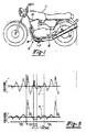
- a motorcycle powered by an internal combustion engine constructed in accordance with an embodiment of the invention is shown partially in phantom and is identified generally by the reference numeral 11.
- the motorcycle 11 includes a powering internal combustion engine 12 which, in the illustrated embodiment, is depicted as being of the four cylinder, inline type.
- the engine 12, in the illustrated embodiment, is of the four-cycle type, however, it is to be understood that the invention may be practiced with engines operating on the two-stroke cycle, and on engines having differing numbers of cylinders and different cylinder arrangements. Also, the invention is susceptible of use in other than reciprocating engines.
- the invention has utility in engines of the type wherein there is a substantial overlap between the closing of the exhaust valve and the opening of the intake valve or, in the case of a two-cycle engine, the closing of the exhaust port and the opening of the intake port. Also, the invention can be practiced with single cylinder engines but has particularly utility in multiple cylinder engines.
- the engine has an intake port and an exhaust port which are controlled either by valves, piston movement or the like, depending upon whether the engine is of the two or four-cycle type and that there is a substantial overlap between the opening of the intake valve and the closing of the exhaust valve as will be described.
- the engine 12 and its exhaust system 13 may be considered to be conventional.
- the engine 12 is designed to be of the high output type and has a substantial overlap in its valve timing.
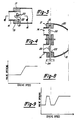
- the engine 12, with its exhaust system 13 and without considering the operation of the valve mechanism 17, will product a torque curve as shown in Figure 6.
- the torque curve of a convention engine of this type is shown by the curve c.
- the torque curve is extremely good and provides a high power.
- the intermediate ranges (C) the torque curve falls off rather badly and these are the normal cruising speeds of the engine.
- the idle condition and low speed (B) the torque is also not good and poor running results.
- valve mechanism 17 is employed for preventing the existence of such positive pressures at the exhaust port during the overlap period and under predetermined running conditions.
- valve assembly 17 includes a valve body 19 that has a plurality of passages 21 that cooperate with the exhaust pipe outlets 14 to deliver exhaust gases to a collector section 20 that discharges into the expansion chamber 16.
- a control valve 22 which acts as a reflective device under certain conditions, as to be described, for controlling the pressure at the exhaust ports of the engine.
- the control valves 22 are all affixed to a common control valve shaft 23 that is journaled in a suitable manner in the valve body 19. At one end of the shaft 23, there is provided a control pulley 24 around which is wound a flexible transmitter 25.
- the transmitter 25 is, in turn, operated by means of a control motor 26 that may be of any known type motor such as a vacuum motor, electric motor, electric solenoid or the like.
- the control motor 26 is, in turn, operated by means of a logic device 27 that controls the position of the valves 22 in response to preset conditions. These preset conditions may be either engine speed, carburetor throttle valve position, boost pressure (in the event the engine is super-charged), engine load, or any other type of arrangement for providing the necessary control signal in response to the running condition.
- the cross-sectional area of the reflective control valve 22 is such that when they are fully closed, as shown in the solid line view of Figure 3, that they will obstruct approximately one-half of the effective cross-sectional area of the exhaust pipes 14. In certain embodiments, this ratio has been found to give a good overall effect although different relations may be used with other engines. Also, even though butterfly type valves 22 are used in the illustrated embodiment, other type of valves or reflective devices may be used.
- the torque curve c demands some control during the ranges B and C in order to improve the performance.
- the valves 22 are maintained fully closed until the engine speed reaches a predetermined speed, such as at the point X and then the valves gradually are opened until they reach their fully opened position at the approximate upper end of the mid-range curve.
- the curve a in Figure 6 shows the effect of the closing of the valves 22.
- the curve a is generated by keeping the valves 22 in their fully closed position throughout the entire engine speed and load ranges. It will be seen that there is a significant improvement in torque during the ranges B and C and that the torque then falls off from the maximum torque curve during the high speed range A. Thus, if the valves 22 are maintained closed up until the transition between the point C and E, a torque curve will result which is the torque curve a up until this point and then the torque curve becomes the curve c. Therefore, it should be readily apparent that this device is effective in significantly improving the torque at mid-range running.
- the conventional engine torque curve c has better performance at certain speeds between idle and half engine speed and thus, the performance can still further be improved by controlling the valve 22 so that they fully open under this condition and then again close as shown in Figure 9.
- the actual tuning of the operation and closure of the valves 22 may be readily determined by those skilled in the art in order to achieve maximum performance for a given engine.
Landscapes
- Engineering & Computer Science (AREA)
- Chemical & Material Sciences (AREA)
- Combustion & Propulsion (AREA)
- Mechanical Engineering (AREA)
- General Engineering & Computer Science (AREA)
- Characterised By The Charging Evacuation (AREA)
Priority Applications (3)
| Application Number | Priority Date | Filing Date | Title |
|---|---|---|---|
| ES198787101883T ES2041651T3 (es) | 1987-02-11 | 1987-02-11 | Sistema de escape de alto rendimiento para motor de combustion interna. |
| DE8787101883T DE3786164T2 (de) | 1987-02-11 | 1987-02-11 | Hochleistungsauspuffanlage fuer brennkraftmaschine. |
| EP87101883A EP0278033B1 (fr) | 1987-02-11 | 1987-02-11 | Système d'échappement à haute performance pour moteur à combustion interne |
Applications Claiming Priority (1)
| Application Number | Priority Date | Filing Date | Title |
|---|---|---|---|
| EP87101883A EP0278033B1 (fr) | 1987-02-11 | 1987-02-11 | Système d'échappement à haute performance pour moteur à combustion interne |
Publications (2)
| Publication Number | Publication Date |
|---|---|
| EP0278033A1 true EP0278033A1 (fr) | 1988-08-17 |
| EP0278033B1 EP0278033B1 (fr) | 1993-06-09 |
Family
ID=8196746
Family Applications (1)
| Application Number | Title | Priority Date | Filing Date |
|---|---|---|---|
| EP87101883A Expired - Lifetime EP0278033B1 (fr) | 1987-02-11 | 1987-02-11 | Système d'échappement à haute performance pour moteur à combustion interne |
Country Status (3)
| Country | Link |
|---|---|
| EP (1) | EP0278033B1 (fr) |
| DE (1) | DE3786164T2 (fr) |
| ES (1) | ES2041651T3 (fr) |
Cited By (3)
| Publication number | Priority date | Publication date | Assignee | Title |
|---|---|---|---|---|
| WO1991013243A1 (fr) * | 1990-02-21 | 1991-09-05 | Noise Cancellation Technologies, Inc. | Commande active de la performance de machines |
| EP0479342A3 (en) * | 1986-09-13 | 1992-07-08 | Yamaha Motor Co., Ltd. | High performance exhaust system for internal combustion engine |
| RU2258816C2 (ru) * | 2002-10-28 | 2005-08-20 | Закрытое акционерное общество "НАУЧНО-ПРОИЗВОДСТВЕННЫЙ ЦЕНТР "ЭкоМотор" | Устройство для глушения шума выхлопа двигателя внутреннего сгорания |
Citations (4)
| Publication number | Priority date | Publication date | Assignee | Title |
|---|---|---|---|---|
| FR761047A (fr) * | 1933-08-01 | 1934-03-08 | Moteur à explosion ou à combustion | |
| DE946268C (de) * | 1952-10-16 | 1956-07-26 | Bayerische Motoren Werke Ag | Vorrichtung zur Verbesserung der Spuelung und Fuellung einer Brennkraftmaschine |
| DE946930C (de) * | 1940-07-30 | 1956-08-09 | Kloeckner Humboldt Deutz Ag | Brennkraftmaschine, insbesondere Zweitaktbrennkraftmaschine |
| US3703937A (en) * | 1971-05-21 | 1972-11-28 | William L Tenney | Multiple rpm range tuned exhaust pipe and silencer for two-cycle engine |
Family Cites Families (1)
| Publication number | Priority date | Publication date | Assignee | Title |
|---|---|---|---|---|
| US2717583A (en) * | 1951-11-09 | 1955-09-13 | Maybach | Control system for internal combustion engines |
-
1987
- 1987-02-11 DE DE8787101883T patent/DE3786164T2/de not_active Expired - Lifetime
- 1987-02-11 EP EP87101883A patent/EP0278033B1/fr not_active Expired - Lifetime
- 1987-02-11 ES ES198787101883T patent/ES2041651T3/es not_active Expired - Lifetime
Patent Citations (4)
| Publication number | Priority date | Publication date | Assignee | Title |
|---|---|---|---|---|
| FR761047A (fr) * | 1933-08-01 | 1934-03-08 | Moteur à explosion ou à combustion | |
| DE946930C (de) * | 1940-07-30 | 1956-08-09 | Kloeckner Humboldt Deutz Ag | Brennkraftmaschine, insbesondere Zweitaktbrennkraftmaschine |
| DE946268C (de) * | 1952-10-16 | 1956-07-26 | Bayerische Motoren Werke Ag | Vorrichtung zur Verbesserung der Spuelung und Fuellung einer Brennkraftmaschine |
| US3703937A (en) * | 1971-05-21 | 1972-11-28 | William L Tenney | Multiple rpm range tuned exhaust pipe and silencer for two-cycle engine |
Non-Patent Citations (1)
| Title |
|---|
| PATENT ABSTRACTS OF JAPAN, vol. 11, no. 175 (M-596)[2622], 5th June 1987; & JP-A-62 007 924 (HONDA MOTOR CO. LTD.) 14-01-1987 * |
Cited By (5)
| Publication number | Priority date | Publication date | Assignee | Title |
|---|---|---|---|---|
| EP0479342A3 (en) * | 1986-09-13 | 1992-07-08 | Yamaha Motor Co., Ltd. | High performance exhaust system for internal combustion engine |
| WO1991013243A1 (fr) * | 1990-02-21 | 1991-09-05 | Noise Cancellation Technologies, Inc. | Commande active de la performance de machines |
| AU638808B2 (en) * | 1990-02-21 | 1993-07-08 | Noise Cancellation Technologies, Inc. | Active control of machine performance |
| US5431008A (en) * | 1990-02-21 | 1995-07-11 | Noise Cancellation Technologies, Inc. | Active control of machine performance |
| RU2258816C2 (ru) * | 2002-10-28 | 2005-08-20 | Закрытое акционерное общество "НАУЧНО-ПРОИЗВОДСТВЕННЫЙ ЦЕНТР "ЭкоМотор" | Устройство для глушения шума выхлопа двигателя внутреннего сгорания |
Also Published As
| Publication number | Publication date |
|---|---|
| DE3786164D1 (de) | 1993-07-15 |
| ES2041651T3 (es) | 1993-12-01 |
| DE3786164T2 (de) | 1993-09-23 |
| EP0278033B1 (fr) | 1993-06-09 |
Similar Documents
| Publication | Publication Date | Title |
|---|---|---|
| US4702218A (en) | Engine intake system having a pressure wave supercharger | |
| US5000131A (en) | Exhaust port control valve for two stroke engine | |
| US5660155A (en) | Four-cycle engine | |
| US4630446A (en) | Outboard motor with turbo-charger | |
| US5311848A (en) | Induction system for engine | |
| US4488531A (en) | Plural intake system for supercharged engine | |
| US4998512A (en) | Exhaust port control system for two stroke engine | |
| US4528958A (en) | Intake control system of engine | |
| US4909033A (en) | High performance exhaust system for internal combustion engine | |
| US4488519A (en) | Intake system for four-cycle engines | |
| US4637210A (en) | Supercharge pressure control apparatus of a supercharged engine | |
| US4912930A (en) | High performance exhaust system for internal combustion engine | |
| US7467625B1 (en) | Flexible fuel impulse charged engine assembly | |
| US4627396A (en) | Intake control system of engine | |
| EP0278033B1 (fr) | Système d'échappement à haute performance pour moteur à combustion interne | |
| EP0278032B1 (fr) | Système d'échappement à haute performance pour moteur à combustion interne | |
| CA1281292C (fr) | Systeme d'echappement haute performance pour moteur a combustion interne | |
| CA1281293C (fr) | Systeme d'echappement haute performance pour moteur a combustion interne | |
| JPH0125883B2 (fr) | ||
| JPH0232827Y2 (fr) | ||
| US4471615A (en) | Turbo and inertia supercharger | |
| JPH0123654B2 (fr) | ||
| JP2523320B2 (ja) | タ−ボエンジンの排気システム | |
| JPS6361496B2 (fr) | ||
| JPH0315805Y2 (fr) |
Legal Events
| Date | Code | Title | Description |
|---|---|---|---|
| PUAI | Public reference made under article 153(3) epc to a published international application that has entered the european phase |
Free format text: ORIGINAL CODE: 0009012 |
|
| AK | Designated contracting states |
Kind code of ref document: A1 Designated state(s): DE ES FR GB IT |
|
| 17P | Request for examination filed |
Effective date: 19890217 |
|
| 17Q | First examination report despatched |
Effective date: 19890626 |
|
| GRAA | (expected) grant |
Free format text: ORIGINAL CODE: 0009210 |
|
| RAP1 | Party data changed (applicant data changed or rights of an application transferred) |
Owner name: YAMAHA MOTOR CO., LTD. |
|
| AK | Designated contracting states |
Kind code of ref document: B1 Designated state(s): DE ES FR GB IT |
|
| REF | Corresponds to: |
Ref document number: 3786164 Country of ref document: DE Date of ref document: 19930715 |
|
| ITF | It: translation for a ep patent filed | ||
| ET | Fr: translation filed | ||
| REG | Reference to a national code |
Ref country code: ES Ref legal event code: FG2A Ref document number: 2041651 Country of ref document: ES Kind code of ref document: T3 |
|
| PLBE | No opposition filed within time limit |
Free format text: ORIGINAL CODE: 0009261 |
|
| STAA | Information on the status of an ep patent application or granted ep patent |
Free format text: STATUS: NO OPPOSITION FILED WITHIN TIME LIMIT |
|
| 26N | No opposition filed | ||
| REG | Reference to a national code |
Ref country code: GB Ref legal event code: IF02 |
|
| PGFP | Annual fee paid to national office [announced via postgrant information from national office to epo] |
Ref country code: GB Payment date: 20060208 Year of fee payment: 20 |
|
| PGFP | Annual fee paid to national office [announced via postgrant information from national office to epo] |
Ref country code: DE Payment date: 20060209 Year of fee payment: 20 |
|
| PGFP | Annual fee paid to national office [announced via postgrant information from national office to epo] |
Ref country code: IT Payment date: 20060228 Year of fee payment: 20 |
|
| PGFP | Annual fee paid to national office [announced via postgrant information from national office to epo] |
Ref country code: ES Payment date: 20060317 Year of fee payment: 20 |
|
| PG25 | Lapsed in a contracting state [announced via postgrant information from national office to epo] |
Ref country code: GB Free format text: LAPSE BECAUSE OF EXPIRATION OF PROTECTION Effective date: 20070210 |
|
| PG25 | Lapsed in a contracting state [announced via postgrant information from national office to epo] |
Ref country code: ES Free format text: LAPSE BECAUSE OF EXPIRATION OF PROTECTION Effective date: 20070212 |
|
| REG | Reference to a national code |
Ref country code: GB Ref legal event code: PE20 |
|
| REG | Reference to a national code |
Ref country code: ES Ref legal event code: FD2A Effective date: 20070212 |
|
| PGFP | Annual fee paid to national office [announced via postgrant information from national office to epo] |
Ref country code: FR Payment date: 20060228 Year of fee payment: 20 |