EP0278043A2 - Mounting support for blood bags - Google Patents
Mounting support for blood bags Download PDFInfo
- Publication number
- EP0278043A2 EP0278043A2 EP87109849A EP87109849A EP0278043A2 EP 0278043 A2 EP0278043 A2 EP 0278043A2 EP 87109849 A EP87109849 A EP 87109849A EP 87109849 A EP87109849 A EP 87109849A EP 0278043 A2 EP0278043 A2 EP 0278043A2
- Authority
- EP
- European Patent Office
- Prior art keywords
- blood bag
- holder
- blood
- jaws
- clamping
- Prior art date
- Legal status (The legal status is an assumption and is not a legal conclusion. Google has not performed a legal analysis and makes no representation as to the accuracy of the status listed.)
- Granted
Links
Images


Classifications
-
- B—PERFORMING OPERATIONS; TRANSPORTING
- B04—CENTRIFUGAL APPARATUS OR MACHINES FOR CARRYING-OUT PHYSICAL OR CHEMICAL PROCESSES
- B04B—CENTRIFUGES
- B04B5/00—Other centrifuges
- B04B5/04—Radial chamber apparatus for separating predominantly liquid mixtures, e.g. butyrometers
- B04B5/0407—Radial chamber apparatus for separating predominantly liquid mixtures, e.g. butyrometers for liquids contained in receptacles
- B04B5/0428—Radial chamber apparatus for separating predominantly liquid mixtures, e.g. butyrometers for liquids contained in receptacles with flexible receptacles
-
- B—PERFORMING OPERATIONS; TRANSPORTING
- B04—CENTRIFUGAL APPARATUS OR MACHINES FOR CARRYING-OUT PHYSICAL OR CHEMICAL PROCESSES
- B04B—CENTRIFUGES
- B04B5/00—Other centrifuges
- B04B5/04—Radial chamber apparatus for separating predominantly liquid mixtures, e.g. butyrometers
- B04B5/0407—Radial chamber apparatus for separating predominantly liquid mixtures, e.g. butyrometers for liquids contained in receptacles
- B04B2005/0435—Radial chamber apparatus for separating predominantly liquid mixtures, e.g. butyrometers for liquids contained in receptacles with adapters for centrifuge tubes or bags
Definitions
- the invention relates to a holder for blood bags in centrifuges according to the preamble of claim 1.
- Such mounts have become known in various embodiments. All embodiments have in common that pins or hooks are arranged on the holder and the blood bag to be held in each case is attached to these pins or hooks with its openings arranged in the edge region.
- the known holders try to solve the problem, the blood bag in the peripheral area, i.e. thus also in the connection area where the connection tubes open into the blood bag, so that there is no kinking of the tubes and the edge area during the centrifugation process. If such a kinking occurred, erytrocytes would be trapped in this area, and if the blood bag was released from its holder after the centrifugation process had taken place, these trapped erytrocytes would flow into the blood plasma now produced and contaminate this plasma.
- DE-GM 7 314 447, DE-GM 7 224 121 and DE-OS 2 142 737 provide opposing clamping jaws on the upper part of each blood bag, which are clamped in the edge area of the blood bag, pins of the clamping jaws reach through the openings in the edge area of the blood bag.
- the disadvantage here is that tearing out of the more or less full blood bags depending on the filling state and centrifugal force is not avoided with certainty.
- the object of the invention is to develop a holder for blood bags of the type mentioned in such a way that the hanging and unhooking of the blood bags in the holder is made considerably easier and that damage to the blood bags by handling or pivoting before centrifuging can be avoided if the holder operates reliably. especially pulling out when centrifuging.
- the invention is characterized in that the bolts forming the suspension of the blood bag are arranged on jaws, which can be hung on a central part above oblong holes or hooks on a horizontal shaft above the cups by means of angled legs, the jaws swing to the center part under centrifugal force.
- a blood bag with its intended openings is placed on the bolts of a cheek with bent legs and remains there in a rest position without any clamping action being provided which could damage the blood bag.
- the hoses of the blood bag are simply led out upwards when the blood bag is hooked onto the bolts of the cheek. This eliminates the need to thread the hoses, since no further part is initially provided on the jaws, which could have a clamping effect.
- the blood bag In this fastening position, the blood bag can be handled or pivoted without a clamping action already provided which could lead to damage to the blood bag.
- the blood bag For centrifugation, the blood bag is inserted into a beaker, the bent legs, on the cheek of which the blood bag hangs, are suspended in a horizontal shaft by means of an oblong hole.
- the edge region of the blood bag which could lead to damage. Only when centrifuging does the cheek press against the edge of the blood bag due to the centrifugal force.
- the jaws are each integrally assigned to two bent legs.
- the pins forming the suspension of the blood bag are arranged on a fastening part on which clamping jaws are mounted, which overlap the pins and press the centrifugal force of increasing clamping force against the edge region of the blood bag.
- pins are not provided on the clamping jaws, but rather on a fastening part of the cup, and that clamping jaws are also arranged in the edge area of the blood bag and thus also in the connection area of the tubes, which clamps the contact pressure in the edge area of the blood bag during the centrifugation process reinforce.
- a first preferred embodiment according to the subject of claim 5 provides that each jaw is attached to the free, pivotable end of a cranked lever, the pivot axis of the lever being arranged on the fastening part.
- the jaw is understood as the weight on the free, pivotable part of a lever which is pivoted on one side on the fastening part and the lever is bent so that when a centrifugal force acts, the lever is pivoted due to the weight of the jaw and thereby the jaw is caused by the increasingly strong centrifugation force is pressed against the fastening part.
- the additional advantage is achieved that the increasing clamping force upon the action of a centrifugal force supports the edge area of the blood bag produced by welding and thus this edge area from tearing out, Warps, unfolds and the like protects.
- the essential advantage is achieved that the clamping force, which increases during the centrifugation process, does not load the openings in the blood bag, which are attached to the pins, with the centrifugation force, which would entail the risk of tearing out, but rather the entire edge area of the Blood bag is supported by the jaws and pressed against the fastener, thereby resulting these openings are protected from being torn out.
- the inventive concept of the present invention not only comprises an arrangement with two blood bags, each blood bag being assigned a clamping jaw, but it is also possible to design a holding part in such a way that only a single blood bag is held and fixed with an associated clamping jaw.
- a particularly space-saving construction results when using two blood bags according to the subject matter of claim 6 when the holding part engages in the space between the cups with a shoulder and there with is connected to the cups, and that in each case a clamping jaw, each with a blood bag, is pivotably mounted on levers, which are all located in the same pivot axis.
- the blood bag is easy to hold, because the swivel jaw can simply be swiveled up without loosening the corresponding holding device, the blood bag is then hung up on the released pins and the swivel jaw is simply released, which means that it returns to its rest position due to its weight falls, which corresponds to the clamping position at the same time. All parts are held captive on the fastening part, and no complicated insertion or detachment of different parts is required, as are known in the prior art.
- FIG. 1 the invention is shown with two cups 7, 8, which are attached to a central part 41.
- the central part 41 has a continuous horizontal shaft 35 in a bore in the upper region, slots being provided in the center of the central part 41 according to FIGS. 2 and 3, in which the shaft 35 is exposed. 5, which are each arranged in pairs on a jaw 38 according to FIG. 4, are hooked onto the shaft 35 via elongated holes 36 according to FIG. 1.
- the blood bags not shown here, have solidified openings in the upper edge region, into which the bolts 37 according to FIG. 5 are inserted in pairs.
- the bolts 37 consist of a shaft and a bolt head 43 which protects the blood bag against slipping out.
- the blood bag then hangs freely on the bolt 37 of the leg 34 with the jaw 38 according to FIG. 5 and is inserted from this position into a cup 7 according to FIG. 1 or FIG. 2.
- they In a certain pivot position of the jaws 38, they are pushed onto the shaft 35 via the slot-like bore 36 of the leg 34 and pivoted downward. A firm bond of the cup 7 with the blood bags on the bolts 37 of the jaws 34 with respect to the central part 41 and its shaft 35 is thus achieved.
- the bent legs 34 are then pushed over the shaft 35 and the weight-loaded jaws 38 are pivoted down into their rest or fastening position, so that there is then a clear fastening.
- the tubes of the blood bag are advantageously very simply attached.
- the hoses are first led out on recesses 44 according to FIGS. 2, 4 and 6 of the clamping jaws 38 and fixed by hand when the legs 34 are suspended in the shaft 35.
- the otherwise necessary threading of the hoses through clamping devices is thus eliminated, since the jaws 38 on the side of the bolts 37 are open.
- the jaws 38 pivot in the direction of the arrow 42, in particular under the action of the forces which occur in the longitudinal direction of the cups 7, 8 during centrifugation.
- the bolts 37 are inserted with their shafts in holes 40 in the jaws 38.
- the central part 41 has a bore 39 in which the bolts 37 face each other with their bolt heads 43 in the manner of a stop.
- Fig. 3 shows the relatively large one-piece design of the jaws 38 and the arrangement of the legs 34 on the shaft 35.
- the central part 41 has lateral troughs, with the aid of which the entire holder can be grasped.
- the entire holder with the cups 7, 8 is suspended in an arm of the centrifuging device via bores in the central part 41, which are not shown here.
- Fig. 2 shows the oval design of the cups 7, 8, which are attached with their straight sides to the central part 41, preferably by riveting. It can here several smaller cups can also be provided symmetrically or a single cup with one or two jaws on a horizontal shaft 35.
- each blood bag 28 rests in an associated cup 7, 8, both cups 7, 8 being connected to one another by a fastening part 1 in that in the space 6 between the cups 7, 8 the fastening part 1 engages with a shoulder 5 and in the area this approach, a rivet connection 9 is provided, which connects the cups 7, 8 to the approach 5.
- the cups 7, 8 together with the holder according to the invention are inserted into the suspension of a centrifuge in a manner known per se, the centrifuging force acting in the direction of the arrow 25.
- Each blood bag has, in a manner known per se, an edge region 30, which is produced by welding and which passes into a cavity filled with blood or, depending on the intended use, filled with another liquid, which essentially fills the cup 7, 8 in each case.
- Tubes adjoin the edge region 30 of the blood bag 28, only one tube 29 being shown in the exemplary embodiment according to FIG.
- the object of the holder according to the invention is now to generate a clamping force in the edge area 3O of the blood bag, so that the edge area 3O is securely supported during the centrifugation process and at the same time the tubes 29 are guided out of the blood bag 28 while avoiding kinks.
- two spaced slots 17 are provided on the upper side of the fastening part, into which one end of each lever 2 pivotably engages, the pivot axis being formed by a dowel pin 18 extending through the entire bore of the fastening part 1.
- the respective lever 2 is supported with its end with play in the slot 17 in order to ensure easy pivoting.
- the diameter of the head 10 is dimensioned such that it fits tightly through the opening of the blood bag, as a result of which the opening of the blood bag then lies on the shaft of the reduced diameter of the pin 4.
- a bore 24 according to FIG. 8 is arranged on the underside of the fastening part on each side of the fastening part 1, into which a stay bolt, not shown, engages, which in turn engages is firmly connected to the hanger of the centrifuge and looks out of the hanger at the top.
- each pin 4 engages in an associated recess 2O on the inside of the jaw 3, the depth 32 (see FIG. 10) is chosen so that it is avoided with certainty that the head 10 of the pin 4 to the bottom the recess 2O strikes when the jaw is pressed in the direction of arrow 26 with its inner clamping surface against the fastening part 1.
- the clamping surface of the respective jaw 3 is formed by clamping grooves 23, which receive recesses 12 to 16 between them, through which the tubes 29 of the blood bag 28 are led out without being kinked or pressed.
- a bevel 33 (see FIG. 10) is provided in order to prevent the clamping jaw from contacting the blood bag outside the edge region 30 of the blood bag 28 and possibly including any liquid located there.
- the fastening part 1 is provided on its upper side according to FIG. 8 with opposing recessed grips 22, so that the entire fastening part 1 together with the cups attached to it can be easily removed from the hanger of the centrifuge, as a result of which the bores 24 with the stud bolts (not shown) on the hanger disengage.
- the clamping jaw is simply pivoted upwards in the opposite direction to the direction of arrow 26, a holding bevel 31 being provided on the outside of the clamping jaw according to FIG. 10 in order to ensure favorable gripping with the fingers.
- the pin 4 is exposed and the blood bag 28 is placed with its opening on the pin, as a result of which the head 10 slips through the opening with a slight deformation of the opening and the blood bag then on the shaft reduced diameter of the pin 4 rests.
- the clamping jaw is simply released and swivels automatically under the influence of its weight in the direction of arrow 26 into the position shown in FIG. 7, the hose outlets resting correctly in the recesses 12-16 according to FIG. 12.
Landscapes
- External Artificial Organs (AREA)
- Centrifugal Separators (AREA)
- Medical Preparation Storing Or Oral Administration Devices (AREA)
Abstract
Bei der Erfindung sind die Blutbeutel in Becher eingelegt, und die vorgesehenen Öffnungen im Randbereich der Blutbeutel sind in Bolzen eingehängt, welche entweder feststehend an einem Mittenteil der Halterung oder beweglich an schwenkbaren Backen vorgesehen sind. Die gewichtsbelasteten Backen sind schwenkbar über abgekröpfte Schenkel an der Halterung angeordnet und pressen unter der Einwirkung der Zentrifugalkraft auf den Randbereich der Blutbeutel, wodurch sich bei steigender Umdrehungszahl beim Zentrifugieren eine stetig verfestigende Klemmverbindung der Blutbeutel in der Halterung ergibt. 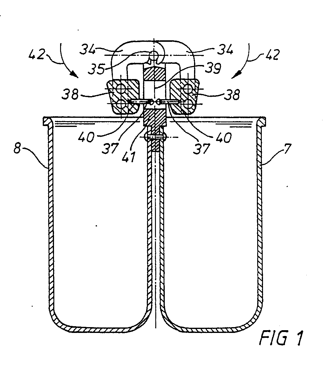
Description
Die Erfindung betrifft eine Halterung für Blutbeutel in Zentrifugen nach dem Oberbegriff des Patentanspruchs 1.The invention relates to a holder for blood bags in centrifuges according to the preamble of
Derartige Halterungen sind in vielfältigen Ausführungsformen bekannt geworden. Allen Ausführungsformen ist gemeinsam, daß an der Halterung Stifte oder Haken angeordnet sind und der jeweils zu halternde Blutbeutel mit seinem im Randbereich angeordneten Öffnungen auf diese Stifte oder Haken aufgesteckt wird. Die bekannten Halterungen versuchen das Problem zu lösen, den Blutbeutel im Randbereich, d.h. also auch im Anschlußbereich, wo die Anschlußschläuche in den Blutbeutel münden, aufrecht zu halten, damit es während des Zentrifugationsvorganges nicht zu einem Abknicken der Schläuche und des Randbereiches kommt. Würde nämlich en solches Abknicken passieren, dann würden in diesem Bereich Erytrozyten eingeschlossen werden, und wenn nach erfolgtem Zentrifugationsvorgang der Blutbeutel aus seiner Halterung gelöst wird, würden diese eingeschlossenen Erytrozyten in das nun hergestellte Blutplasma einfließen und dieses Plasma verunreinigen.Such mounts have become known in various embodiments. All embodiments have in common that pins or hooks are arranged on the holder and the blood bag to be held in each case is attached to these pins or hooks with its openings arranged in the edge region. The known holders try to solve the problem, the blood bag in the peripheral area, i.e. thus also in the connection area where the connection tubes open into the blood bag, so that there is no kinking of the tubes and the edge area during the centrifugation process. If such a kinking occurred, erytrocytes would be trapped in this area, and if the blood bag was released from its holder after the centrifugation process had taken place, these trapped erytrocytes would flow into the blood plasma now produced and contaminate this plasma.
Man hat sich bisher stets mit Platten geholfen, welche den Randbereich des Blutbeutels stützen, um ein Abknicken dieses Randbereiches und der dort geführten Anschlußschläuche während des Zentrifugationsvorganges zu vermeiden.So far, it has always been used with plates which support the edge area of the blood bag in order to avoid kinking of this edge area and the connecting tubes guided there during the centrifugation process.
Nachteil der bekannten Halterungen ist jedoch, daß beim Einhängen und Aushängen des Blutbeutels in die bekannte Halterung ein hoher Arbeitsaufwand verbunden ist, und weiterer Nachteil ist, daß die Halte- und Klemmkraft der Stützeinrichtungen dieser Halterungen relativ gering ist.The disadvantage of the known brackets, however, is that Hanging and unhooking the blood bag in the known holder involves a lot of work, and a further disadvantage is that the holding and clamping force of the support devices of these holders is relatively low.
Weitere bekannte Halterungen nach dem DE-GM 7 314 447, dem DE-GM 7 224 121 und der DE-OS 2 142 737 sehen am oberen Teil jedes Blutbeutels einander gegenüberstehende Klemmbacken vor, die im Randbereich der Blutbeutel verspannt werden, wobei Stifte der Klemmbacken die Öffnungen im Randbereich der Blutbeutel durchgreifen.Further known holders according to DE-GM 7 314 447, DE-GM 7 224 121 and DE-OS 2 142 737 provide opposing clamping jaws on the upper part of each blood bag, which are clamped in the edge area of the blood bag, pins of the clamping jaws reach through the openings in the edge area of the blood bag.
Nachteilig hierbei ist es, daß ein Ausreißen der mehr oder weniger vollen Blutbeutel in Abhängigkeit vom Füllzustand und Zentrifugalkraft nicht mit Sicherheit vermieden wird.The disadvantage here is that tearing out of the more or less full blood bags depending on the filling state and centrifugal force is not avoided with certainty.
Aufgabe der Erfindung ist es, eine Halterung für Blutbeutel der genannten Art so weiterzubilden, daß das Ein- und Aushängen der Blutbeutel in die Halterung wesentlich vereinfacht wird und daß bei betriebssicherer Arbeitsweise der Halterung Beschädigungen der Blutbeutel durch Hantieren oder Schwenken vor dem Zentrifugieren vermieden werden, insbesondere ein Ausreißen beim Zentrifugieren.The object of the invention is to develop a holder for blood bags of the type mentioned in such a way that the hanging and unhooking of the blood bags in the holder is made considerably easier and that damage to the blood bags by handling or pivoting before centrifuging can be avoided if the holder operates reliably. especially pulling out when centrifuging.
Zur Lösung der gestellten Aufgabe ist die Erfindung dadurch gekennzeichnet, daß die die Aufhängung des Blutbeutels bildenden Bolzen an Backen angeordnet sind, welche mittels abgekröpfter Schenkel über langlochartige Bohrungen bzw. Haken an einer horizontalen Welle oberhalb der Becher an einem Mittenteil einhängbar sind, wobei die Backen unter der Zentrifugalkraft an das Mittenteil schwenken.To achieve the object, the invention is characterized in that the bolts forming the suspension of the blood bag are arranged on jaws, which can be hung on a central part above oblong holes or hooks on a horizontal shaft above the cups by means of angled legs, the jaws swing to the center part under centrifugal force.
Wesentliches Merkmal der vorliegenden Erfindung ist es demnach, daß ein Blutbeutel mit seinen vorgesehenen Öffnungen auf Bolzen einer Backe mit abgekröpften Schenkeln aufgesteckt wird und dort in einer Ruhelage verbleibt, ohne daß schon irgendeine Klemmwirkung vorgesehen wäre, die zur Beschädigung der Blutbeutel führen könnte.It is therefore an essential feature of the present invention that a blood bag with its intended openings is placed on the bolts of a cheek with bent legs and remains there in a rest position without any clamping action being provided which could damage the blood bag.
Die Schläuche des Blutbeutels werden in einfacher Weise beim Einhängen des Blutbeutels auf die Bolzen der Backe nach oben herausgeführt. Dadurch entfällt ein Durchfädeln der Schläuche, da an den Backen zunächst kein weiteres Teil vorgesehen ist, was eine Klemmwirkung ausüben könnte.The hoses of the blood bag are simply led out upwards when the blood bag is hooked onto the bolts of the cheek. This eliminates the need to thread the hoses, since no further part is initially provided on the jaws, which could have a clamping effect.
In dieser Befestigungslage kann mit dem Blutbeutel hantiert werden oder dieser kann geschwenkt werden, ohne daß eine jetzt schon vorgesehene Klemmwirkung zu einer Beschädigung des Blutbeutels führen könnte.In this fastening position, the blood bag can be handled or pivoted without a clamping action already provided which could lead to damage to the blood bag.
Zum Zentrifugieren wird der Blutbeutel in einen Becher eingeführt, wobei die abgekröpften Schenkel, an deren Backe der Blutbeutel hängt, in eine horizontale Welle mittels einer langlochartigen Bohrung eingehängt werden. Auch hierbei ist noch keine sonderliche Klemmwirkung auf den Randbereich des Blutbeutels vorgesehen, die zu Beschädigungen führen könnte. Erst beim Zentrifugieren pressen sich die Backen infolge der Zentrifugalkraft an den Randbereich der Blutbeutel an.For centrifugation, the blood bag is inserted into a beaker, the bent legs, on the cheek of which the blood bag hangs, are suspended in a horizontal shaft by means of an oblong hole. Here, too, there is no special clamping effect on the edge region of the blood bag, which could lead to damage. Only when centrifuging does the cheek press against the edge of the blood bag due to the centrifugal force.
Die Backen sind jeweils einstückig zwei abgekröpften Schenkeln zugeordnet.The jaws are each integrally assigned to two bent legs.
Hierdurch ergibt sich eine vorteilhafte betriebssichere symmetrische Anordnung der Schenkel mit den Backen, wobei je nach Umdrehungszahl der Zentrifugiereinheit verschieden große gewichtsbelastete Backen vorgesehen sein können.This results in an advantageous, reliable, symmetrical arrangement of the legs with the jaws, wherein depending on the number of revolutions of the centrifuging unit, differently sized weight-loaded jaws can be provided.
Eine weitere Lösung der gestellten Aufgabe sieht in einem anderen Ausführungsbeispiel vor, daß die die Aufhängung des Blutbeutels bildenden Stifte an einem Befestigungsteil angeordnet sind, an dem Klemmbacken gelagert sind, welche die Stifte übergreifen und unter Zentrifugationskraft sich vergrößernder Klemmkraft gegen den Randbereich des Blutbeutels pressen.Another solution to the problem is provided in another embodiment, that the pins forming the suspension of the blood bag are arranged on a fastening part on which clamping jaws are mounted, which overlap the pins and press the centrifugal force of increasing clamping force against the edge region of the blood bag.
Wesentliches Merkmal ist es hier, daß die Stifte nicht an den Klemmbacken, sondern an einem Befestigungste1 der Becher vorgesehen sind und daß im Randbereich des Blutbeutels und damit auch im Anschlußbereich der Schläuche ebenfalls Klemmbacken angeordnet sind, welche den Anpreßdruck im Randbereich des Blutbeutels während des Zentrifugatungsvorganges verstärken. Hierdurch kommt es bei immer höherer Umdrehungszahl der Zentrifuge zu einer sich verfestigenden Klemmverbindung, wie sie bisher noch nicht bekannt war. Alle bisher bekannten Klemmverbindungen sind unabhängig von der Zentrifugationskraft.An essential feature here is that the pins are not provided on the clamping jaws, but rather on a fastening part of the cup, and that clamping jaws are also arranged in the edge area of the blood bag and thus also in the connection area of the tubes, which clamps the contact pressure in the edge area of the blood bag during the centrifugation process reinforce. This results in a solidifying clamp connection, as was previously unknown, with an ever increasing number of revolutions of the centrifuge. All previously known clamp connections are independent of the centrifugation force.
Zur Ausbildung von Klemmbacken, deren Klemmkraft sich unter Zentrifugationskraft vergrößert, gibt es mehrere verschiedene Ausführungsformen. Alle Ausführungsformen werden vom Erfindungsgedanken der vorliegenden Erfindung umfaßt.There are several different embodiments for forming clamping jaws, the clamping force of which increases under centrifuging force. All embodiments are encompassed by the inventive concept of the present invention.
Eine erste bevorzugte Ausführungsform nach dem Gegenstand des Anspruches 5 sieht vor, daß jede Klemmbacke am freien, schwenkbaren Ende eines abgekröpften Hebels befestigt ist, wobei die Schwenkachse des Hebels am Befestigungsteil angeordnet ist. Die Klemmbacke wird so als Gewicht am freien, schwenkbaren Teil eines einseitig schwenkbar am Befestigungsteil gelagerten Hebels aufgefaßt und der Hebel ist so abgekröpft, daß bei Einwirkung einer Zentrifugationskraft der Hebel gewichtsbedingt durch das Gewicht der Klemmbacke verschwenkt wird und dadurch die Klemmbacke bedingt durch die immer stärker werdende Zentrifugationskraft an das Befestigungsteil angedrückt wird. Neben der ausgezeichneten Stützung des Randbereiches des Blutbeutels und der Stützung der durch die Klemmbacken in entsprechenden Ausnehmungen herausgeführten Schläuche wird der zusätzliche Vorteil erzielt, daß die bei Einwirken einer Zentrifugationskraft sich vergrößernde Klemmkraft den durch Verschweißung hergestellten Randbereich des Blutbeutels stützt und diesen Randbereich damit vor Ausreißen, Verziehen, Auffalten und dergleichen schützt.A first preferred embodiment according to the subject of
Darüber hinaus wird der wesentliche Vorteil erzielt, daß durch die während des Zentrifugationsvorganges stärker werdende Klemmkraft die im Blutbeutel angeordneten Öffnungen, welche auf die Stifte aufgesteckt sind, nicht mit der Zentrifugationskraft belastet werden, womit die Gefahr des Ausreißens verbunden wäre, sondern der gesamte Randbereich des Blutbeutels wird durch die Klemmbacken gestützt und an das Befestigungsteil angepreßt, wodurch demzufolge diese Öffnungen vor dem Ausreißen geschützt werden.In addition, the essential advantage is achieved that the clamping force, which increases during the centrifugation process, does not load the openings in the blood bag, which are attached to the pins, with the centrifugation force, which would entail the risk of tearing out, but rather the entire edge area of the Blood bag is supported by the jaws and pressed against the fastener, thereby resulting these openings are protected from being torn out.
Vom Erfindungsgedanken der vorliegenden Erfindung wird nicht nur eine Anordnung mit zwei Blutbeuteln umfaßt, wobei jedem Blutbeutel eine Klemmbacke zugeordnet ist, sondern es ist ebenso möglich, ein Halterungsteil so auszubilden, daß nur ein einziger Blutbeutel mit einer zugeordneten Klemmbacke gehalten und fixiert wird.The inventive concept of the present invention not only comprises an arrangement with two blood bags, each blood bag being assigned a clamping jaw, but it is also possible to design a holding part in such a way that only a single blood bag is held and fixed with an associated clamping jaw.
Ein besonders raumsparender Aufbau ergibt sich bei der Verwendung von zwei Blutbeuteln nach dem Gegenstand des Anspruches 6 dann, wenn das Halterungsteil im Zwischenraum zwischen die Becher mit einem Ansatz greift und dort mit den Bechern verbunden ist, und daß auf dem Befestigungsteil jeweils eine Klemmbacke mit jeweils einem Blutbeutel schwenkbar über Hebel gelagert sind, welche alle in der gleichen Schwenkachse liegen.A particularly space-saving construction results when using two blood bags according to the subject matter of claim 6 when the holding part engages in the space between the cups with a shoulder and there with is connected to the cups, and that in each case a clamping jaw, each with a blood bag, is pivotably mounted on levers, which are all located in the same pivot axis.
Mit der Verwendung von schwenkbar gelagerten Klemmbacken ist eine einfache Halterung des Blutbeutels gegeben, denn die Schwenkbacke kann einfach ohne Lösen entsprechender Halterungsvorrichtung hochgeschwenkt werden, der Blutbeutel wird dann auf die freiwerdenden Stifte aufgehängt und die Schwenkbacke wird einfach losgelassen, wodurch sie gewichtsbedingt wieder in ihre Ruhestellung fällt, die gleichzeitig der Klemmstellung entspricht. Alle Teile sind unverlierbar an dem Befestiggungsteil gehalten, und es bedarf keines komplizierten Aufsteckens oder Lösens unterschiedlicher Teile, wie sie beim Stand der Technik bekannt sind.With the use of pivotably mounted clamping jaws, the blood bag is easy to hold, because the swivel jaw can simply be swiveled up without loosening the corresponding holding device, the blood bag is then hung up on the released pins and the swivel jaw is simply released, which means that it returns to its rest position due to its weight falls, which corresponds to the clamping position at the same time. All parts are held captive on the fastening part, and no complicated insertion or detachment of different parts is required, as are known in the prior art.
Der Erfindungsgegenstand der vorliegenden Erfindung ergibt sich nicht nur aus dem Gegenstand der einzelnen Patentansprüche, sondern auch aus der Kombination der einzelnen Patentansprüche untereinander. Alle in den Unterlagen offenbarten Angaben und Merkmale, insbesondere die in den Zeichnungen dargestellte räumliche Ausbildung werden als erfindungswesentlich beansprucht, soweit sie einzeln oder in Kombination gegenüber dem Stand der Technik neu sind.The subject matter of the present invention results not only from the subject matter of the individual patent claims, but also from the combination of the individual patent claims with one another. All of the information and features disclosed in the documents, in particular the spatial design shown in the drawings, are claimed to be essential to the invention, insofar as they are new to the prior art, individually or in combination.
Im folgenden wird die Erfindung anhand von lediglich einen Ausführungsweg darstellende Zeichnungen näher erläutert. Hierbei gehen aus den Zeichnungen und ihrer Beschreibung weitere erfindungswesentliche Merkmale und Vorteile der Erfindung hervor. Es zeigen:
- Fig. 1 eine seitliche Schnittdarstellung der Halterung mit Becher nach der Erfindung mit eingehängten Backen,
- Fig. 2 eine Draufsicht der Halterung nach Fig. 1,
- Fig. 3 eine Seitenansicht der Halterung nach Fig. 1,
- Fig. 4 eine Draufsicht auf eine Backe,
- Fig. 5 eine Seitenansicht einer Backe mit Bolzen,
- Fig. 6 Seitenansicht einer Backe von innen,
- Fig. 7 Schnitt durch eine Halterung nach einer weiteren Ausführung der Erfindung zur Halterung von zwei Blutbeuteln,
- Fig. 8 Seitenansicht mit teilweisem Schnitt durch das Befestigungsteil,
- Fig. 9 Stirnansicht des Befestigungsteils nach Fig. 8,
- Fig. 1O Schnitt durch eine Klemmbacke,
- Fig. 11 Seitenansicht einer Klemmbacke von außen,
- Fig. 12 Draufsicht auf eine Klemmbacke,
- Fig. 13 Seitenansicht eines Stiftes zur Halterung des Blutbeutels,
- Fig. 14 Seitenansicht des Hebels zur Schwenklagerung der Klemmbacken.
- 1 is a sectional side view of the holder with cup according to the invention with hooked jaws,
- 2 is a plan view of the bracket of FIG. 1,
- 3 is a side view of the bracket of FIG. 1,
- 4 is a plan view of a jaw,
- 5 is a side view of a jaw with bolts,
- 6 side view of a cheek from the inside,
- 7 section through a holder according to a further embodiment of the invention for holding two blood bags,
- 8 side view with partial section through the fastening part,
- 9 end view of the fastening part of FIG. 8,
- 1O section through a jaw,
- 11 side view of a jaw from the outside,
- 12 top view of a clamping jaw,
- 13 side view of a pin for holding the blood bag,
- Fig. 14 side view of the lever for pivoting the jaws.
In Fig. 1 ist die Erfindung mit zwei Bechern 7,8 gezeigt, die an einem Mittenteil 41 befestigt sind. Das Mittenteil 41 weist im oberen Bereich in einer Bohrung eine durchgehende horizontale Welle 35 auf, wobei in der Mitte des Mittenteils 41 nach Fig. 2 und Fig. 3 Schlitze vorgesehen sind, in denen die Welle 35 freiliegt. An die Welle 35 werden die abgekröpften Schenkel 34 nach Fig. 5, die jeweils paarweise an einer Backe 38 nach Fig. 4 angeordnet sind, über langlochartige Bohrungen 36 gemäß Fig. 1 eingehängt.In Fig. 1, the invention is shown with two
Die hier nicht dargestellten Blutbeutel weisen im oberen Randbereich verfestigte Öffnungen auf, in welche die Bolzen 37 nach Fig. 5 paarweise eingeführt werden. Die Bolzen 37 bestehen aus einem Schaft und einem Bolzenkopf 43, der den Blutbeutel gegen Herausrutschen schützt. Der Blutbeutel hängt dann frei an den Bolzen 37 des Schenkels 34 mit der Backe 38 nach Fig. 5 und wird von dieser Lage aus in einen Becher 7 nach Fig. 1 oder Fig. 2 eingeführt. In einer bestimmten Schwenklage der Backen 38 werden diese über die langlochartige Bohrung 36 des Schenkels 34 auf die Welle 35 aufgesteckt und nach unten abgeschwenkt. Damit wird ein fester Verbund des Bechers 7 mit den Blutbeuteln an Bolzen 37 der Backen 34 in Bezug auf das Mittenteil 41 und deren Welle 35 erreicht.The blood bags, not shown here, have solidified openings in the upper edge region, into which the
Dies bedeutet, daß vor dem Aufstecken der Backen 38 mit ihren abragenden Schenkeln 34 auf die Welle 35 die Blutbeutel auf die von der Innenseite der Backe 38 abragenden Bolzen 37 aufgesteckt werden. Die so zugerichteten Blutbeutel werden dann in die Becher 7,8 hineingesteckt und dann werden die Backen 38 etwas nach oben geschwenkt, damit die Bohrungen 36 der Langlöcher auf die Welle 35 greifen.This means that before the
Die abgekröpften Schenkel 34 werden dann über die Welle 35 geschoben und die gewichtsbelasteten Backen 38 werden nach unten in ihre Ruhe- oder Befestigungsstellung geschwenkt, so daß dann eine eindeutige Befestigung vorliegt.The
Vorteilhaft werden die hier nicht dargestellten Schläuche der Blutbeutel sehr einfach befestigt. Die Schläuche werden zunächst an Ausnehmungen 44 nach Fig. 2, Fig. 4 und Fig. 6 der Klemmbacken 38 herausgeführt und beim Einhängen der Schenkel 34 in die Welle 35 mit der Hand fixiert. Es entfällt somit das sonst notwendige Durchfädeln der Schläuche durch Klemmeinrichtungen, da die Backen 38 auf der Seite der Bolzen 37 offen sind.The tubes of the blood bag, not shown here, are advantageously very simply attached. The hoses are first led out on
Nach Fig. 1 schwenken die Backen 38, hier in Darstellung ohne Blutbeutel, in Pfeilrichtung 42, insbesondere unter der Wirkung der Kräfte, die in Längsrichtung der Becher 7,8 beim Zentrifugieren auftreten. Die Bolzen 37 sind mit ihren Schäften in Bohrungen 4O in den Klemmbacken 38 ingesetzt. Das Mittenteil 41 weist eine Bohrung 39 auf, in der die Bolzen 37 nach Art eines Anschlags mit ihren Bolzenköpfen 43 gegenüberstehen.According to FIG. 1, the
Fig. 3 zeigt die relativ große einstückige Ausführung der Backen 38 und die Anordnung der Schenkel 34 an der Welle 35. Das Mittenteil 41 weist seitliche Mulden auf, mit Hilfe derer die gesamte Halterung erfaßt werden kann. Die gesamte Halterung mit den Bechern 7,8 wird über hier nicht dargestellte Bohrungen des Mittenteils 41 in einen Arm der Zentrifugiereinrichtung eingehängt.Fig. 3 shows the relatively large one-piece design of the
Fig. 2 zeigt die ovale Ausführung der Becher 7,8, die mit ihren gerade verlaufenden Seiten an dem Mittenteil 41 vorzugsweise durch Vernietungen angebracht sind. Es können hier auch symmetrisch mehrere kleinere Becher vorgesehen sein oder auch ein einzelner Becher mit einer oder zwei Backen an einer horizontalen Welle 35.Fig. 2 shows the oval design of the
Im Ausführungsbeispiel nach Fig. 7 werden zwei Blutbeutel 28 durch die erfindungsgemäße Halterung gehalten. Jeder Blutbeutel 28 ruht hierbei in einem zugeordneten Becher 7,8, wobei beide Becher 7,8 durch ein Befestigungsteil 1 dadurch miteinander verbunden sind, daß in dem Zwischenraum 6 zwischen den Bechern 7,8 das Befestigungsteil 1 mit einem Ansatz 5 greift und im Bereich dieses Ansatzes eine Nietverbindung 9 vorgesehen ist, welche die Becher 7,8 mit dem Ansatz 5 verbindet.7, two
Die Becher 7,8 zusammen mit der erfindungsgemäßen Halterung werden in an sich bekannter Weise in das Gehänge einer Zentrifuge eingesteckt, wobei die Zentrifugationskraft in Pfeilrichtung 25 wirkt.The
Jeder Blutbeutel weist in an sich bekannter Weise einen durch Verschweißung hergestellten Randbereich 3O auf, der in einem mit Blut gefüllten oder - entsprechend dem Einsatzzweck mit einer anderen Flüssigkeit gefüllten - Hohlraum übergeht, der im wesentlichen jeweils den Becher 7,8 ausfüllt.Each blood bag has, in a manner known per se, an
Am Randbereich 3O des Blutbeutels 28 schließen Schläuche an, wobei im Ausführungsbeispiel nach Figur 7 lediglich ein einziger Schlauch 29 gezeigt ist.Tubes adjoin the
Aufgabe der erfindungsgemäßen Halterung ist es nun, im Randbereich 3O des Blutbeutels eine Klemmkraft zu erzeugen, so daß der Randbereich 3O während des Zentrifugationsvorganges sicher abgestützt wird und gleichzeitig die Schläuche 29 gerade unter Vermeidung von Knickungen aus dem Blut beutel 28 herausgeführt sind.The object of the holder according to the invention is now to generate a clamping force in the edge area 3O of the blood bag, so that the edge area 3O is securely supported during the centrifugation process and at the same time the
Hierzu sind an der Oberseite des Befestigungsteils zwei beabstandete Schlitze 17 vorgesehen, in welche schwenkbar das eine Ende jeweils eines Hebels 2 eingreift, wobei die Schwenkachse durch einen die gesamte Bohrung des Befestigungsteils 1 durchgreifenden Paßstift 18 gebildet wird. Der jewelige Hebel 2 ist mit seinem Ende unter Spiel in dem Schlitz 17 gelagert, um eine leichte Verschwenkung zu gewährleisten.For this purpose, two spaced
Der Einfachheit halber wird in der folgenden Beschreibung nur die Halterung des einen Blutbeutels 28 beschrieben, weil die Halterung des gegenüberliegenden Blutbeutels genau identisch ist und symmetrisch zur Längsmittenachse der Figur 1 ausgerichtet ist.For the sake of simplicity, only the holder of the one
Im Bereich der Breitseite des Befestigungsteils 1 nach Fig. 8 sind zwei - einen gegenseitigen Abstand aufweisende - GEwindebohrungen 21 vorgesehen, in die jeweils der Gewindeschaft eines Stiftes (Figur 13) eingeschraubt ist. Jeder Stift weist einen Kopf 1O vergrößerten Durchmessers auf, der in einen Schaft geringeren Durchmessers übergeht.In the area of the broad side of the
Der Durchmesser des Kopfes 1O ist so bemessen, daß er stramm durch die Öffnung des Blutbeutels hindurchpaßt, wodurch die Öffnung des Blutbeutels dann auf dem Schaft verringerten Durchmessers des Stiftes 4 liegt.The diameter of the
Damit die gesamte Anordnung passend und ohne Spiel in ein zugeordnetes Gehänge der Zentrifuge eingehängt werden kann, ist an der Unterseite des Befestigungsteils an jeder Seite des Befestigungsteils 1 eine Bohrung 24 nach Fig. 8 angeordnet, in die ein nicht näher dargestellter Stehbolzen greift, der seinerseits fest mit dem Gehänge der Zentrifuge verbunden ist und oben aus dem Gehänge herausschaut. Auf diese Weise ist stets eine sichere und genaue Zuordnung der gesamten Halterung zusammen mit den Bechern 7,8 zum Gehänge der Zentrifuge gegeben, weil das Befestigungsteil mit seinen zwei, einen gegenseitigen Abstand aufweisenden, Bohrungen 24 auf den Stehbolzen des Gehänges aufgesteckt wird.So that the entire arrangement can be hooked into an associated hanger of the centrifuge in a suitable manner and without play, a
Sofern eine Zentrifugalkraft in Pfeilrichtung 25 einwirkt, werden die Hebel 2 aufgrund ihrer 9O°-Abkröpfung in Pfeilrichtung 26 um die Schwenkachse (Paßstift 18) verschwenkt. Hierdurch werden die Klemmbacken 3 in Pfeilrichtung 27 gegen das Befestigungsteil 1 gepreßt, wobei entsprechend den Messungen des Anmelders bei normalem Zentrifugationsvorgang eine Anpreßkraft von 15O kg erzeugt wird. Jeder Klemmbacke 3 sind hierbei zwei Hebel 2 zugeordnet, wobei zur Verbindung der Klemmbacke 3 mit dem Hebel 2 zwei übereinanderliegende Bohrungen in der jeweiligen Klemmbacke 3 vorgesehen sind (vergl. Fig. 1 und Fig. 7) und die Bohrung axial durch einen durchgehenden Paßstift 11 durchgriffen wird.If a centrifugal force acts in the direction of the
Gemäß Figur 7 greift jeder Stift 4 in eine zugeordnete Ausnehmung 2O an der Innenseite der Klemmbacke 3 ein, wobei die Tiefe 32 (vergl. Figur 1O) so gewählt ist, daß mit Sicherheit vermieden wird, daß der Kopf 1O des Stiftes 4 an den Grund der Ausnehmung 2O anschlägt, wenn die Klemmbacke in Pfeilrichtung 26 mit ihrer inneren Klemmfläche gegen das Befestigungsteil 1 gepreßt wird.According to Figure 7, each
Die Klemmfläche der jeweiligen Klemmbacke 3 wird durch Klemmrillen 23 gebildet, welche zwischen sich Ausnehmungen 12 bis 16 aufnehmen, durch welche die Schläuche 29 des Blutbeutels 28 herausgeführt werden, ohne geknickt oder gepreßt zu werden.The clamping surface of the
An der Unterseite der Klemmfläche ist eine Schräge 33 (vergl. Figur 1O) vorgesehen, um zu vermeiden, daß die Klemmbacke außerhalb des Randbereichs 3O des Blutbeutels 28 am Blutbeutel anliegt und möglicherweise dort befindliche Flüssigkeit einschließt.On the underside of the clamping surface, a bevel 33 (see FIG. 10) is provided in order to prevent the clamping jaw from contacting the blood bag outside the
Das Befestigungsteil 1 ist an seiner Oberseite gemäß Figur 8 mit einander gegenüberliegenden Griffmulden 22 versehen, so daß das gesamte Befestigungsteil 1 zusammen mit den daran befestigten Bechern leicht vom Gehänge der Zentrifuge abgezogen werden kann, wodurch die Bohrungen 24 mit den nicht näher dargestellten Stehbolzen am Gehänge außer Eingriff kommen.The
Zur Befestigung des Blutbeutels 28 an der Halterung wird die Klemmbacke von Hand einfach in Gegenrichtung zur Pfeilrichtung 26 nach oben verschwenkt, wobei an der Außenseite der Klemmbacke gemäß Figur 1O eine Halteschräge 31 vorgesehen ist, um ein günstiges Greifen mit den Fingern zu gewährleisten.To fasten the
Nach der Verschwenkung der jeweiligen Klemmbacke 3 in Gegenrichtung zur Pfeilrichtung 26 liegt der Stift 4 frei und der Blutbeutel 28 wird mit seiner Öffnung auf dem Stift aufgesteckt, wodurch der Kopf 1O unter leichter Verformung der Öffnung durch die Öffnung hindurchschlüpft und der Blutbeutel dann auf dem Schaft verringerten Durchmessers des Stiftes 4 aufliegt.After the
Die Klemmbacke wird einfach losgelassen und verschwenkt selbsttätig unter dem Einfluß ihres Gewichtes in Pfeilrichtung 26 in die in Figur 7 dargestellte Lage, wobei die Schlauchauslässe mit richtigem Sitz in den Ausnehmungen 12-16 nach Fig. 12 anliegen.The clamping jaw is simply released and swivels automatically under the influence of its weight in the direction of
In einer Weiterbildung der vorliegenden Erfindung kann es vorgesehen sein, daß im Bereich der Klemmrillen 23 jeweils ein Permanentmagnet angeordnet ist, der mit einem zugeordneten Eisenstreifen in der gegenüberliegenden Fläche des Befestigungsteils zusammenwirkt, so daß dadurch eine magnetische Halterung der Klemmtacken in der in Fig. 7 gezeigten Lage gezeigt ist. Dies bewirkt, daß auch wenn die gesamte Halterung schräg gehalten wird, die Klemmbacken nicht in Gegenrichtung zur eingezeichneten Pfeilrichtung 26 wegschwenken, was im übrigen auch nicht problematisch ist, denn der Kopf 1O vergrößerten Durchmessers am Stift 4 hält sicher den Blutbeutel vor dem Herabfallen.In a further development of the present invention, it can be provided that in the area of the clamping
Wenn die Zentrifuge dann in Gang gesetzt wird, wirkt die Zentrifugalkraft dann in Pfeilrichtung 25, und aufgrund der exzentrischen Halterung der Klemmbacken 3 in Bezug zur Befestigungsvorrichtung kommt es zu einer Verschwenkung in Pfeilrichtung 26 und damit zu einer Verfestigung der Klemmverbindung im Bereich der Klemmrillen 23 in Richtung zum Befestigungsteil 1. Wie eingangs bereits schon ausgeführt, können damit Klemmkräfte bis zu 15O kg zwischen Klemmbacke und Befestigungsteil erzeugt werden.When the centrifuge is then started, the centrifugal force then acts in the direction of the
- 1 Befestigungsteil1 fastening part
- 2 Hebel2 levers
- 3 Klemmbacke3 jaws
- 4 Stift4 pin
- 5 Ansatz5 approach
- 6 Zwischenraum6 space
- 7 Becher7 cups
- 8 Becher8 cups
- 9 Nietverbindung9 riveted joint
- 1O Kopf (Stift 4)1O head (pin 4)
- 11 Paßstift11 dowel pin
- 12 Ausnehmung12 recess
- 13 Ausnehmung13 recess
- 14 Ausnehmung14 recess
- 15 Ausnehmung15 recess
- 16 Ausnehmung16 recess
- 17 Schlitz17 slot
- 18 Paßstift18 dowel pin
- 19 Schlitz19 slot
- 2O Ausnehmung2O recess
- 21 Gewindebohrung21 threaded hole
- 22 Fingermulde22 finger recess
- 23 Klemmrille23 clamping groove
- 24 Bohrung24 hole
- 25 Pfeilrichtung25 direction of arrow
- 26 Pfeilrichtung26 direction of arrow
- 27 Pfeilrichtung27 direction of arrow
- 28 Blutbeutel28 blood bags
- 29 Schlauch29 hose
- 3O Randbereich3O edge area
- 31 Schräge31 slant
- 32 Tiefe (Ausnehmung 2O)32 depth (recess 2O)
- 33 Schräge33 slant
- 34 abgekröpfter Schenkel34 cranked thighs
- 35 Welle35 wave
- 36 Bohrung36 hole
- 37 Bolzen37 bolts
- 38 Backen38 baking
- 39 Mittenbohrung39 center hole
- 4O Bohrung4O hole
- 41 Mittenteil41 middle part
- 42 Pfeilrichtung42 arrow direction
- 43 Bolzenkopf43 bolt head
- 44 Ausnehmungen44 recesses
Claims (10)
Priority Applications (1)
| Application Number | Priority Date | Filing Date | Title |
|---|---|---|---|
| AT87109849T ATE67435T1 (en) | 1987-02-10 | 1987-07-08 | HOLDER FOR BLOOD BAG. |
Applications Claiming Priority (2)
| Application Number | Priority Date | Filing Date | Title |
|---|---|---|---|
| DE19873704007 DE3704007C1 (en) | 1986-06-18 | 1987-02-10 | Mounting for blood bag |
| DE3704007 | 1987-02-10 |
Publications (3)
| Publication Number | Publication Date |
|---|---|
| EP0278043A2 true EP0278043A2 (en) | 1988-08-17 |
| EP0278043A3 EP0278043A3 (en) | 1989-06-07 |
| EP0278043B1 EP0278043B1 (en) | 1991-09-18 |
Family
ID=6320624
Family Applications (1)
| Application Number | Title | Priority Date | Filing Date |
|---|---|---|---|
| EP87109849A Expired - Lifetime EP0278043B1 (en) | 1987-02-10 | 1987-07-08 | Mounting support for blood bags |
Country Status (3)
| Country | Link |
|---|---|
| EP (1) | EP0278043B1 (en) |
| AT (1) | ATE67435T1 (en) |
| DE (1) | DE3773178D1 (en) |
Cited By (5)
| Publication number | Priority date | Publication date | Assignee | Title |
|---|---|---|---|---|
| DE4331138C1 (en) * | 1993-09-14 | 1995-01-05 | Heinz Kruessel | Blood bag holder |
| EP1637172A1 (en) * | 2004-09-21 | 2006-03-22 | Andreas Hettich GmbH & Co. KG | Device and method for separating blood components stored in bags, and accompanying cup for blood bags |
| US7744821B2 (en) | 2004-09-21 | 2010-06-29 | Andreas Hettich Gmbh & Co. Kg | Blood bag cup for centrifuges |
| EP2651491B1 (en) | 2010-12-14 | 2018-09-12 | Maco Pharma | Device intended to break at least one closure element located inside a flexible tube |
| CN117085862A (en) * | 2023-09-19 | 2023-11-21 | 郑州中科生物医学工程技术研究院 | A kind of blood bag warehouse for centrifuge |
Family Cites Families (1)
| Publication number | Priority date | Publication date | Assignee | Title |
|---|---|---|---|---|
| DE7314447U (en) * | 1973-04-16 | 1973-07-26 | Heraeus Christ Gmbh | DEVICE FOR INSERTING BLOOD BAGS IN SWIVEL CUPS OF CENTRIFUGES |
-
1987
- 1987-07-08 AT AT87109849T patent/ATE67435T1/en not_active IP Right Cessation
- 1987-07-08 EP EP87109849A patent/EP0278043B1/en not_active Expired - Lifetime
- 1987-07-08 DE DE8787109849T patent/DE3773178D1/en not_active Expired - Lifetime
Cited By (5)
| Publication number | Priority date | Publication date | Assignee | Title |
|---|---|---|---|---|
| DE4331138C1 (en) * | 1993-09-14 | 1995-01-05 | Heinz Kruessel | Blood bag holder |
| EP1637172A1 (en) * | 2004-09-21 | 2006-03-22 | Andreas Hettich GmbH & Co. KG | Device and method for separating blood components stored in bags, and accompanying cup for blood bags |
| US7744821B2 (en) | 2004-09-21 | 2010-06-29 | Andreas Hettich Gmbh & Co. Kg | Blood bag cup for centrifuges |
| EP2651491B1 (en) | 2010-12-14 | 2018-09-12 | Maco Pharma | Device intended to break at least one closure element located inside a flexible tube |
| CN117085862A (en) * | 2023-09-19 | 2023-11-21 | 郑州中科生物医学工程技术研究院 | A kind of blood bag warehouse for centrifuge |
Also Published As
| Publication number | Publication date |
|---|---|
| ATE67435T1 (en) | 1991-10-15 |
| DE3773178D1 (en) | 1991-10-24 |
| EP0278043B1 (en) | 1991-09-18 |
| EP0278043A3 (en) | 1989-06-07 |
Similar Documents
| Publication | Publication Date | Title |
|---|---|---|
| CH657551A5 (en) | DRILLING DEVICE. | |
| EP0278043B1 (en) | Mounting support for blood bags | |
| DE3601127A1 (en) | LOAD HANGER WITH IMPROVED HOOK BOLT | |
| DE1941854C3 (en) | Rack for storing bar material | |
| DE2846068C2 (en) | Fastening device for pipes or the like. Objects | |
| DE3030041C2 (en) | Load attachment device provided with a movable attachment device, for example an eyelet | |
| DE3704007C1 (en) | Mounting for blood bag | |
| EP0240785A1 (en) | Holding pliers | |
| DE1965496B2 (en) | Tension lever lock for footwear, in particular ski boots | |
| DE3418342C2 (en) | Device for attaching and releasing hooks | |
| DE1481800B1 (en) | LIFTING CLAW | |
| DE69812386T2 (en) | ROPE BLOCKING DEVICE AND MILKING DEVICE REMOVAL DEVICE WITH SUCH A ROPE BLOCKING DEVICE | |
| DE653799C (en) | Scaffolding clamp with a U-shaped coupling link | |
| CH388894A (en) | Device for holding at least one sleeve displaceably mounted on a vertical rod in the case of laundry hanging devices which can be folded up like an umbrella | |
| DE2621719B2 (en) | Device for extending the holding brackets in electrical installation devices | |
| DE19520009A1 (en) | Self clamping line fastener, e.g. for rope | |
| DE69907670T2 (en) | DEVICE FOR CONNECTING A VEHICLE WITH A RICHTBANK | |
| EP1300360A1 (en) | Load engaging hook with shortening claw | |
| DE3525322A1 (en) | Device for fastening at least one container | |
| DE102009038392A1 (en) | Device for repositioning bones, particularly of sections of breast bone after heart operation, has threads or wires and surgical thread turner, which comprises hook element for holding threads or wires and handle | |
| DE2707397C2 (en) | Housings for electrical equipment | |
| DE466644C (en) | Artificial working hand that can be connected to an arm stump base | |
| AT16916U1 (en) | FAILURE SAFETY DEVICE AND SAFETY DEVICE | |
| DE3930766C1 (en) | Erecting device for hospital bed aid - comprises support tube and bearer tube with fitted clamping slide for handle | |
| DE3504920A1 (en) | Device for hanging the wishbone boom on the mast of a surfboard |
Legal Events
| Date | Code | Title | Description |
|---|---|---|---|
| PUAI | Public reference made under article 153(3) epc to a published international application that has entered the european phase |
Free format text: ORIGINAL CODE: 0009012 |
|
| AK | Designated contracting states |
Kind code of ref document: A2 Designated state(s): AT BE CH DE FR GB IT LI NL SE |
|
| PUAL | Search report despatched |
Free format text: ORIGINAL CODE: 0009013 |
|
| AK | Designated contracting states |
Kind code of ref document: A3 Designated state(s): AT BE CH DE FR GB IT LI NL SE |
|
| 17P | Request for examination filed |
Effective date: 19891104 |
|
| 17Q | First examination report despatched |
Effective date: 19901130 |
|
| GRAA | (expected) grant |
Free format text: ORIGINAL CODE: 0009210 |
|
| AK | Designated contracting states |
Kind code of ref document: B1 Designated state(s): AT BE CH DE FR GB IT LI NL SE |
|
| PG25 | Lapsed in a contracting state [announced via postgrant information from national office to epo] |
Ref country code: IT Free format text: LAPSE BECAUSE OF FAILURE TO SUBMIT A TRANSLATION OF THE DESCRIPTION OR TO PAY THE FEE WITHIN THE PRE;WARNING: LAPSES OF ITALIAN PATENTS WITH EFFECTIVE DATE BEFORE 2007 MAY HAVE OCCURRED AT ANY TIME BEFORE 2007. THE CORRECT EFFECTIVE DATE MAY BE DIFFERENT FROM THE ONE RECORDED.SCRIBED TIME-LIMIT Effective date: 19910918 Ref country code: BE Effective date: 19910918 Ref country code: FR Effective date: 19910918 Ref country code: SE Effective date: 19910918 Ref country code: GB Effective date: 19910918 Ref country code: NL Effective date: 19910918 |
|
| REF | Corresponds to: |
Ref document number: 67435 Country of ref document: AT Date of ref document: 19911015 Kind code of ref document: T |
|
| REF | Corresponds to: |
Ref document number: 3773178 Country of ref document: DE Date of ref document: 19911024 |
|
| EN | Fr: translation not filed | ||
| NLV1 | Nl: lapsed or annulled due to failure to fulfill the requirements of art. 29p and 29m of the patents act | ||
| GBV | Gb: ep patent (uk) treated as always having been void in accordance with gb section 77(7)/1977 [no translation filed] | ||
| PG25 | Lapsed in a contracting state [announced via postgrant information from national office to epo] |
Ref country code: AT Effective date: 19920708 |
|
| PLBE | No opposition filed within time limit |
Free format text: ORIGINAL CODE: 0009261 |
|
| STAA | Information on the status of an ep patent application or granted ep patent |
Free format text: STATUS: NO OPPOSITION FILED WITHIN TIME LIMIT |
|
| PG25 | Lapsed in a contracting state [announced via postgrant information from national office to epo] |
Ref country code: CH Effective date: 19920731 Ref country code: LI Effective date: 19920731 |
|
| 26N | No opposition filed | ||
| REG | Reference to a national code |
Ref country code: CH Ref legal event code: PL |
|
| PGFP | Annual fee paid to national office [announced via postgrant information from national office to epo] |
Ref country code: DE Payment date: 19940824 Year of fee payment: 8 |
|
| PG25 | Lapsed in a contracting state [announced via postgrant information from national office to epo] |
Ref country code: DE Effective date: 19960402 |