EP0278087B1 - Rollwagen mit Längenverschiebungsgestänge - Google Patents
Rollwagen mit Längenverschiebungsgestänge Download PDFInfo
- Publication number
- EP0278087B1 EP0278087B1 EP87118436A EP87118436A EP0278087B1 EP 0278087 B1 EP0278087 B1 EP 0278087B1 EP 87118436 A EP87118436 A EP 87118436A EP 87118436 A EP87118436 A EP 87118436A EP 0278087 B1 EP0278087 B1 EP 0278087B1
- Authority
- EP
- European Patent Office
- Prior art keywords
- guide
- rolling table
- cutting plane
- table according
- displaced
- Prior art date
- Legal status (The legal status is an assumption and is not a legal conclusion. Google has not performed a legal analysis and makes no representation as to the accuracy of the status listed.)
- Expired - Lifetime
Links
- 238000005096 rolling process Methods 0.000 title claims abstract 9
- 235000004607 Chlorophora excelsa Nutrition 0.000 claims abstract description 13
- 244000229769 Chlorophora excelsa Species 0.000 claims abstract description 13
- 238000003754 machining Methods 0.000 claims abstract description 3
- 239000002023 wood Substances 0.000 claims description 9
- 241000309551 Arthraxon hispidus Species 0.000 description 6
- 238000010276 construction Methods 0.000 description 2
- 238000004519 manufacturing process Methods 0.000 description 2
- 238000005259 measurement Methods 0.000 description 2
- 230000001419 dependent effect Effects 0.000 description 1
- 238000010586 diagram Methods 0.000 description 1
Images

Classifications
-
- B—PERFORMING OPERATIONS; TRANSPORTING
- B27—WORKING OR PRESERVING WOOD OR SIMILAR MATERIAL; NAILING OR STAPLING MACHINES IN GENERAL
- B27B—SAWS FOR WOOD OR SIMILAR MATERIAL; COMPONENTS OR ACCESSORIES THEREFOR
- B27B5/00—Sawing machines working with circular or cylindrical saw blades; Components or equipment therefor
- B27B5/16—Saw benches
- B27B5/22—Saw benches with non-feedable circular saw blade
- B27B5/222—Saw benches with non-feedable circular saw blade the saw blade being arranged underneath the work-table; Guiding arrangements for the work-table
-
- B—PERFORMING OPERATIONS; TRANSPORTING
- B23—MACHINE TOOLS; METAL-WORKING NOT OTHERWISE PROVIDED FOR
- B23Q—DETAILS, COMPONENTS, OR ACCESSORIES FOR MACHINE TOOLS, e.g. ARRANGEMENTS FOR COPYING OR CONTROLLING; MACHINE TOOLS IN GENERAL CHARACTERISED BY THE CONSTRUCTION OF PARTICULAR DETAILS OR COMPONENTS; COMBINATIONS OR ASSOCIATIONS OF METAL-WORKING MACHINES, NOT DIRECTED TO A PARTICULAR RESULT
- B23Q1/00—Members which are comprised in the general build-up of a form of machine, particularly relatively large fixed members
- B23Q1/25—Movable or adjustable work or tool supports
- B23Q1/44—Movable or adjustable work or tool supports using particular mechanisms
- B23Q1/48—Movable or adjustable work or tool supports using particular mechanisms with sliding pairs and rotating pairs
- B23Q1/4804—Movable or adjustable work or tool supports using particular mechanisms with sliding pairs and rotating pairs a single rotating pair followed perpendicularly by a single sliding pair
-
- B—PERFORMING OPERATIONS; TRANSPORTING
- B27—WORKING OR PRESERVING WOOD OR SIMILAR MATERIAL; NAILING OR STAPLING MACHINES IN GENERAL
- B27B—SAWS FOR WOOD OR SIMILAR MATERIAL; COMPONENTS OR ACCESSORIES THEREFOR
- B27B27/00—Guide fences or stops for timber in saw mills or sawing machines; Measuring equipment thereon
- B27B27/06—Guide fences or stops for timber in saw mills or sawing machines; Measuring equipment thereon arranged angularly with respect to the plane of the saw blade, e.g. for mitring
-
- B—PERFORMING OPERATIONS; TRANSPORTING
- B27—WORKING OR PRESERVING WOOD OR SIMILAR MATERIAL; NAILING OR STAPLING MACHINES IN GENERAL
- B27B—SAWS FOR WOOD OR SIMILAR MATERIAL; COMPONENTS OR ACCESSORIES THEREFOR
- B27B27/00—Guide fences or stops for timber in saw mills or sawing machines; Measuring equipment thereon
- B27B27/08—Guide fences or stops for timber in saw mills or sawing machines; Measuring equipment thereon arranged adjustably, not limited to only one of the groups B27B27/02 - B27B27/06
-
- B—PERFORMING OPERATIONS; TRANSPORTING
- B27—WORKING OR PRESERVING WOOD OR SIMILAR MATERIAL; NAILING OR STAPLING MACHINES IN GENERAL
- B27B—SAWS FOR WOOD OR SIMILAR MATERIAL; COMPONENTS OR ACCESSORIES THEREFOR
- B27B27/00—Guide fences or stops for timber in saw mills or sawing machines; Measuring equipment thereon
- B27B27/10—Devices for moving or adjusting the guide fences or stops
-
- B—PERFORMING OPERATIONS; TRANSPORTING
- B27—WORKING OR PRESERVING WOOD OR SIMILAR MATERIAL; NAILING OR STAPLING MACHINES IN GENERAL
- B27G—ACCESSORY MACHINES OR APPARATUS FOR WORKING WOOD OR SIMILAR MATERIALS; TOOLS FOR WORKING WOOD OR SIMILAR MATERIALS; SAFETY DEVICES FOR WOOD WORKING MACHINES OR TOOLS
- B27G19/00—Safety guards or devices specially adapted for wood saws; Auxiliary devices facilitating proper operation of wood saws
- B27G19/10—Measures preventing splintering of sawn portions of wood
-
- B—PERFORMING OPERATIONS; TRANSPORTING
- B27—WORKING OR PRESERVING WOOD OR SIMILAR MATERIAL; NAILING OR STAPLING MACHINES IN GENERAL
- B27G—ACCESSORY MACHINES OR APPARATUS FOR WORKING WOOD OR SIMILAR MATERIALS; TOOLS FOR WORKING WOOD OR SIMILAR MATERIALS; SAFETY DEVICES FOR WOOD WORKING MACHINES OR TOOLS
- B27G5/00—Machines or devices for working mitre joints with even abutting ends
- B27G5/02—Machines or devices for working mitre joints with even abutting ends for sawing mitre joints; Mitre boxes
- B27G5/023—Machines or devices for working mitre joints with even abutting ends for sawing mitre joints; Mitre boxes the mitre angle being adjusted by positioning a workpiece relative to a fixed saw
Definitions
- the invention relates to a trolley with length-shift linkage for cutting oblique or studio windows and / or end-face machining with a lower part which can be displaced parallel to the cutting plane via a linear guide and with an upper part which can be pivoted with respect to the lower part and with a longitudinal stop which can be displaced transversely to the cutting plane, at the front end thereof Counter wood is arranged.
- the present invention is therefore based on the object of creating a trolley of the type mentioned, by means of which the counter-timber can be tracked exactly while maintaining the desired dimensions, even in the case of sloping or studio windows.
- this object is achieved in that the length stop is connected to a guide rod which is displaceable transversely to the cutting plane and which is articulated and positively guided on a compensating guide in the front region via a joint head, the compensating guide having such a course that the tip of the Counter wood can also be moved along a straight line parallel to the cutting plane with angle settings.
- the length stop and the associated guide rod must necessarily follow the compensation guide on the cam track. It is only necessary to choose the cam track of the compensation guide according to the design and the structure of the trolley so that the front tip of the counter-timber, which is connected to the length stop, always remains in the desired position in the area of the flight circle diameter or at least is moved approximately parallel to the cutting plane.
- the dimensions are always the same. To do this, it is only necessary to calibrate the scale accordingly, which then remains the same regardless of the angle size even when pivoted.
- the guide rod is pulled out to the front to the desired extent via the connection to the joint head. Due to the fixed connection of the length stop to the guide rod, the front edge of the counter wood remains on a straight line and can thus be set to an optimal distance from the cut. This means that chipping of the wood blank is avoided. Since the length stop is also shifted by the difference in dimensions, the set dimension remains constant with any degree setting.
- the guide rod can be connected to the upper part in a simple manner via two bearing blocks.
- the compensation guide itself can be made using bearing parts of any type, e.g. Slide or roller or ball bearings, to be connected to the lower part.
- the compensation guide is provided with end stops at both ends.
- the design of the joint head can be any. The only requirement is that the connection is articulated. For this purpose, it can have a bolt which is inserted into a bearing bore of a sliding guide which is connected to the compensating guide so as to be displaceable.
- the length stop can be arranged laterally in front of the guide rod and can be connected to the guide rod via two fastening flanges arranged at a distance from one another.
- the length stop for the wood to be processed can be provided with a tab for the wood stop.
- the trolley according to the invention is fundamentally of a known construction, which is why only the parts essential to the invention are described in more detail below. At the same time, this also means that the parts according to the invention can also be retrofitted to known trolleys if necessary.
- the trolley has a fixed lower part 1 and an upper part 2 which can thus be pivoted via a rotating device (not shown).
- the lower part can be moved parallel to the cutting plane 6 of the saw 19 via a linear guide, which has a guide rod 3 with guide bushes 4 and 5.
- a length stop 7 is arranged on the upper part 2, the longitudinal axis of which is perpendicular to the cutting plane 6.
- a counter wood 8 which serves as a system for the wood to be processed, which is placed on the front face 9 of the length stop (see triangle in FIG. 1).
- the counter wood 8 does not have to be made of wood, but in practice it is generally made of plastic.
- the length stop is provided with a scale and a tab 10 as a wooden stop for the length of wood.
- the tab 10 is displaceable in the longitudinal direction of the length stop 7 provided with a scale.
- the length stop 7 is arranged laterally in front of a guide rod 11 and is connected to it fixedly, but releasably by means of screws, by means of two spaced-apart fastening flanges 12.
- the guide rod 11 can in turn be displaced in its longitudinal direction via bearing blocks 13.
- the front end of the guide rod 11 is articulated via a joint head 14 to a compensating guide 15.
- the joint head 14 is provided with a bolt 25 which is secured by a lock nut 16 and which is inserted into a bearing bore 17 of a slide guide 18.
- the sliding guide 18 partially includes the compensating guide 15. In this way, the guide rod 11 is forcibly in the longitudinal direction, i.e. guided along the course of the compensation guide 15.
- the joint head 14 represents a movable node K.
- the compensating guide 15 is fastened to the lower part 1 via bearing parts 20 and has end stops 21 which are designed as screws with stop rings. As can be seen, the compensation guide 15 is a curved or curved rod.
- the compensation guide Y F is described by mirroring the compensation curve Y k around the Y axis and shifting it around B to the new coordinate point 0.
- the reduction S can be calculated using the ray set, namely:
- the compensation guide with the coordinate origin 0 ' should be selected so that a swivel range of a max. can be covered by +/- 60 degrees. This position is shown in principle in FIG. 6.
Landscapes
- Life Sciences & Earth Sciences (AREA)
- Engineering & Computer Science (AREA)
- Mechanical Engineering (AREA)
- Wood Science & Technology (AREA)
- Forests & Forestry (AREA)
- Dovetailed Work, And Nailing Machines And Stapling Machines For Wood (AREA)
- Non-Portable Lighting Devices Or Systems Thereof (AREA)
- Re-Forming, After-Treatment, Cutting And Transporting Of Glass Products (AREA)
Description
- Die Erfindung betrifft einen Rollwagen mit Längenverschiebungsgestänge zum Zuschneiden von Schräg- oder Studiofenstern und/oder stimseitiger Bearbeitung mit einem parallel zur Schnittebene über eine Linearführung verschiebbaren Unterteil und mit einem gegenüber dem Unterteil verschwenkbaren Oberteil mit einem quer zur Schnittebene verschiebbaren Längenanschlag, an dessem vorderen Ende ein Konterholz angeordnet ist.
- Beim Fensterbau gibt es bei der Herstellung von Studiofenstern, wie z.B. Giebelfenster, die nicht rechtwinkelig sind, bei der Maschinenfertigung Probleme beim Anschlagen des Holzes auf einen schräg gestellten Rollwagen. Der Rollwagen muß nämlich jedesmal entsprechend der geforderten Winkelgrade der Fensterschräge eingestellt werden. Durch diese Schrägstellung beschreibt jedoch der auf dem Rollwagen befestigte Längenanschlag einen Kreisbogen. Von Nachteil dabei ist, daß sich durch diese Bewegung das Konterholz, welches auf dem Längenanschlag befestigt ist, von der Ablängsäge und dem Schlitzwerkzeug entfernt. Mit anderen Worten, durch die Schrägstellung gerät das Konterholz aus dem Bereich der Flugkreisdurchmesser der Schlitz- bzw. Zapfwerkzeuge und der Ablängsäge. Außerdem stimmt damit der Anschlag bzw. der Reiter bei dem eingestellten Winkel zur Holzlänge nicht mehr überein und zwar um den Betrag a = 1/cos.
- Schiebt man nun das Konterholz zur Vermeidung einer Aussplitterung beim Sägen weiter nach vorne, dann stimmt das eingestellte Maß nicht mehr. Dies bedeutet, man muß stets die genaue Länge durch probieren und messen auf Maß kontrollieren, wodurch die Herstellung von derartigen Fenstern sehr zeitaufwendig und damit teuer ist.
- Der vorliegenden Erfindung liegt daher die Aufgabe zugrunde, einen Rollwagen der eingangs erwähnten Art zu schaffen, durch den auch bei Schräg- oder Studiofenstern das Konterholz exakt unter Einhaltung des gewünschten Maßes nachführbar ist.
- Erfindungsgemäß wird diese Aufgabe dadurch gelöst, daß der Längenanschlag mit einer Führungsstange verbunden ist, die quer zur Schnittebene verschiebbar ist und die im vorderen Bereich über einen Gelenkkopf an einer Ausgleichsführung angelenkt und zwangsgeführt ist, wobei die Ausgleichsführung einen derartigen Bahnverlauf aufweist, daß die Spitze des Konterholzes auch bei Winkeleinstellungen entlang einer Geraden parallel zur Schnittebene verschiebbar ist.
- Durch die Zwangsführung über die Ausgleichsführung muß der Längenanschlag und die damit verbundene Führungsstange zwangsläufig auf der Kurvenbahn der Ausgleichsführung folgen. Es ist lediglich erforderlich, die Kurvenbahn der Ausgleichsführung entsprechend den konstruktiven Gegebenheiten und dem Aufbau des Rollwagens so zu wählen, daß die vordere Spitze des Konterholzes, das ja mit dem Längenanschlag verbunden ist, stets in der gewünschten Position im Bereich des Flugkreisdurchmessern verbleibt bzw. wenigstens annähernd parallel zur Schnittebene verschoben wird.
- Als weiterer Vorteil ergibt sich dadurch ein stets gleich bleibendes Maß. Hierzu ist es lediglich erforderlich, den Maßstab entsprechend zu eichen, der dann auch bei einem Verschwenken unabhängig von der Winkelgröße gleich bleibt. Praktisch wird mit der erfindungsgemäßen Ausgleichsführung der entstandene Längenunterschied a = 1/cos des eingestellten Winkels beim Drehen des schwenkbaren Teiles des Rolltisches ausgeglichen. Über die Verbindung mit dem Gelenkkopf wird die Führungsstange entsprechend nach vorne in dem gewünschten Maße herausgezogen. Durch die feste Verbindung des Längenanschlages mit der Führungsstange bleibt die Vorderkante des Konterholzes dabei auf einer Geraden und kann damit auf einen optimalen Abstand zum Schnitt eingestellt werden. Dies bedeutet, daß Aussplitterungen des Holzrohlings vermieden werden. Da gleichzeitig auch der Längenanschlag um die Maßdifferenz verschoben wird, bleibt das eingestellte Maß auch bei jeder beliebigen Gradeinstellung konstant.
- In einfacher Weise kann die Verbindung der Führungsstange mit dem Oberteil über zwei Lagerböcke erfolgen.
- Die Ausgleichsführung selbst kann über Lagerteile beliebiger Bauart, z.B. Gleit- oder Wälz- oder Kugellager, mit dem Unterteil verbunden sein.
- Zur Wegbegrenzung und zur Vermeidung von Unfällen kann vorgesehen sein, daß die Ausgleichsführung an ihren beiden Enden mit Endanschlägen versehen ist.
- Die Ausbildung des Gelenkkopfes kann beliebig sein. Voraussetzung ist lediglich, daß die Verbindung gelenkig ist. Hierzu kann er einen Bolzen aufweisen, der in eine Lagerbohrung einer Gleitführung gesteckt ist, die entlang der Ausgleichsführung verschiebbar mit dieser verbunden ist.
- Selbstverständlich sind im Rahmen der Erfindung jedoch auch noch andere gelenkige Verbindungsarten möglich.
- In einfacher Weise kann der Längenanschlag seitlich vor der Führungsstange angeordnet sein und über zwei auf Abstand voneinander angeordnete Befestigungsflansche mit der Führungsstange verbunden sein.
- In bekannter Weise kann der Längenanschlag für das zu bearbeitende Holz mit einem Reiter für den Holzanschlag versehen sein.
- Nachfolgend ist ein Ausführungsbeispiel der Erfindung anhand der Zeichnung prinzipmäßig näher beschrieben.
- Es zeigt:
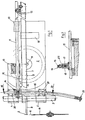
- Fig. 1: eine Draufsicht auf den erfindungsgemäßen Rollwagen
- Fig. 2: eine Seitenansicht (ohne Längenanschlag) des Rollwagens nach der Fig. 1
- Fig. 3: einen Schnitt nach der Linie III-III der Fig. 1
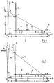
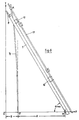
- Fig. 4-6: Prinzipdarstellung der Ausgleichskurve zu deren Berechnung
- Der erfindungsgemäße Rollwagen ist grundsätzlich von bekanntem Aufbau, weshalb nachfolgend nur die für die Erfindung wesentlichen Teile näher beschrieben werden. Gleichzeitig bedeutet dies auch, daß die erfindungsgemäßen Teile im Bedarfsfalle auch nachträglich bei bekannten Rollwagen eingesetzt werden können.
- Der Rollwagen weist einen feststehenden Unterteil 1 und einen damit über eine nicht näher dargestellte Dreheinrichtung verschwenkbaren Oberteil 2 auf. Über eine Linearführung, die eine Führungsstange 3 mit Führungsbuchsen 4 und 5 aufweist, kann das Unterteil parallel zur Schnittebene 6 der Säge 19 verschoben werden.
- Auf dem Oberteil 2 ist ein Längenanschlag 7 angeordnet, dessen Längsachse rechtwinkelig zur Schnittebene 6 liegt. Am vorderen Ende des Längenanschlages 7 befindet sich ein Konterholz 8, das als Anlage für das zu bearbeitende Holz dient, welches an der vorderen Stirnseite 9 des Längenanschlages angelegt wird (siehe Dreieck in der Fig. 1). Selbstverständlich mußB das Konterholz 8 nicht aus Holz bestehen, vielmehr ist es in der Praxis im allgemeinen aus Kunststoff. Der Längenanschlag ist mit einem Maßstab und einem Reiter 10 als Holzanschlag für die Holzlänge versehen. Der Reiter 10 ist in Längsrichtung des mit einer Maßskala versehenen Längenanschlages 7 auf diesem verschiebbar.
- Der Längenanschlag 7 ist seitlich vor einer Führungsstange 11 angeordnet und über zwei auf Abstand voneinander angeordnete Befestigungsflansche 12 mit dieser fest, jedoch lösbar über Schrauben verbunden. Die Führungsstange 11 ist wiederum über Lagerböcke 13 in ihre Längsrichtung verschiebbar.
- Das vordere Ende der Führungsstange 11 ist über einen Gelenkkopf 14 mit einer Ausgleichsführung 15 gelenkig verbunden. Der Gelenkkopf 14 ist mit einem Bolzen 25 versehen, der durch eine Kontermutter 16 gesichert ist und der in eine Lagerbohrung 17 einer Gleitführung 18 gesteckt ist. Die Gleitführung 18 umfaßt teilweise die Ausgleichsführung 15. Auf diese Weise ist die Führungsstange 11 zwangsweise in Längsrichtung d.h. entlang dem Verlauf der Ausgleichsführung 15 geführt. Dabei stellt der Gelenkkopf 14 einen beweglichen Knotenpunkt K dar. Die Ausgleichsführung 15 ist über Lagerteile 20 auf dem Unterteil 1 befestigt und weist Endanschläge 21 auf, die als Schrauben mit Anschlagringen ausgebildet sind. Wie ersichtlich, ist die Ausgleichsführung 15 eine gewölbte bzw. gebogene Stange. Deren Bogen bzw. Radius ist abhängig von dem Drehpunkt M des schwenkbaren Oberteiles 2, dem Abstand des Knotenpunktes K vom Drehpunkt M und dem Abstand des Knotenpunktes von der Spitze S des Konterholzes. Nachfolgend ist deren Bahn in Verbindung mit den Fig. 4 bis 6 dargestellt und berechnet.
- Die Zwangsführung wird als eine Gerade angenommen. Die zur Y-Achse auszugleichende Differenz bei größer werdendem Winkel a läßt sich durch Ausgleichskurve Yk bestimmen. Diese Kurve ist eine Überlagerung zweier trigonometrischer Funktionen:
- Yk = A tanα+B · sin a
- Dabei ist:
- Yk = Ausgleichskurve
- K = Knotenpunkt
- M = Drehpunkt
- a = eingestellter Winkel des Rollwagens
- Die X-werte lassen sich analog mit:
- Xa = β-cosα · B
- bestimmen.
- Die Ausgleichführung YF wird durch eine Spiegelung der Ausgleichskurve Yk um die Y-Achse und Verschiebung um B in den neuen Koordinatenpunkt 0 , beschrieben.
- In dem neuen Schnittpunkt der Geraden G mit Yk und YF müssen die Beträge der X-Werte der jeweiligen Koordinate gleich sein. Daraus ergeben sich kürzere Y-Werte für YF.
- Dabei ist:
- YF = Ausgleichsführung
- Yk = Ausgleichskurve
- M = Drehpunkt
- G = Gerade zum Winkel
- a = eingestellter Winkel des Rollwagens
- Die Kürzung S kann mit des Strahlensatzes berechnet werden und zwar:

- In der Praxis sollte die Ausgleichsführung mit dem Koordinatenursprung 0' so gewählt sein, daß ein Schwenkbereich von a max. von +/- 60 Grad abgedeckt werden kann. In der Fig. 6 ist diese Position prinzipmäßig dargestellt.
Claims (7)
Priority Applications (1)
| Application Number | Priority Date | Filing Date | Title |
|---|---|---|---|
| AT87118436T ATE51792T1 (de) | 1987-02-07 | 1987-12-12 | Rollwagen mit laengenverschiebungsgestaenge. |
Applications Claiming Priority (2)
| Application Number | Priority Date | Filing Date | Title |
|---|---|---|---|
| DE3703805 | 1987-02-07 | ||
| DE3703805A DE3703805C1 (de) | 1987-02-07 | 1987-02-07 | Rollwagen mit Laengenverschiebungsgestaenge |
Publications (2)
| Publication Number | Publication Date |
|---|---|
| EP0278087A1 EP0278087A1 (de) | 1988-08-17 |
| EP0278087B1 true EP0278087B1 (de) | 1990-04-11 |
Family
ID=6320488
Family Applications (1)
| Application Number | Title | Priority Date | Filing Date |
|---|---|---|---|
| EP87118436A Expired - Lifetime EP0278087B1 (de) | 1987-02-07 | 1987-12-12 | Rollwagen mit Längenverschiebungsgestänge |
Country Status (3)
| Country | Link |
|---|---|
| EP (1) | EP0278087B1 (de) |
| AT (1) | ATE51792T1 (de) |
| DE (1) | DE3703805C1 (de) |
Families Citing this family (1)
| Publication number | Priority date | Publication date | Assignee | Title |
|---|---|---|---|---|
| DE4116347C1 (en) * | 1991-05-18 | 1992-08-27 | Gottfried 7099 Adelmannsfelden De Haberkorn | Roller cutter carriage with length shift linkage - has top part main body coupled to swivel bearing with pivot point in work deposition plane |
Family Cites Families (2)
| Publication number | Priority date | Publication date | Assignee | Title |
|---|---|---|---|---|
| DE2910337C2 (de) * | 1979-03-16 | 1987-03-12 | Eugen Lutz GmbH u. Co Maschinenfabrik, 7130 Mühlacker | Kombinierte Tisch- und Gehrungssäge |
| US4441394A (en) * | 1981-12-07 | 1984-04-10 | Mario Barsotti | Table saw guide apparatus |
-
1987
- 1987-02-07 DE DE3703805A patent/DE3703805C1/de not_active Expired
- 1987-12-12 EP EP87118436A patent/EP0278087B1/de not_active Expired - Lifetime
- 1987-12-12 AT AT87118436T patent/ATE51792T1/de active
Also Published As
| Publication number | Publication date |
|---|---|
| DE3703805C1 (de) | 1988-08-25 |
| EP0278087A1 (de) | 1988-08-17 |
| ATE51792T1 (de) | 1990-04-15 |
Similar Documents
| Publication | Publication Date | Title |
|---|---|---|
| DE2503397A1 (de) | Feilenfuehrung | |
| EP0018657A1 (de) | Teilungs- und Parallelzeichnungswinkel | |
| EP1839828B1 (de) | Bearbeitungsmaschine, insbesondere Kreissäge | |
| DE4243054C1 (de) | Vorrichtung zur Bearbeitung der Kantenränder von fortlaufend bewegten plattenförmigen Werkstücken | |
| EP0319032A2 (de) | Zimmerei-Abbundanlage | |
| DE3703805C1 (de) | Rollwagen mit Laengenverschiebungsgestaenge | |
| DE2643268C2 (de) | Vorrichtung zum Brennschneiden | |
| DE2615814C2 (de) | Weiche für geführte Fahrzeuge | |
| DE9015042U1 (de) | Holzbearbeitungsmaschine zur Endenbearbeitung von Rahmenhölzern | |
| EP1245358B1 (de) | Anschlagvorrichtung für eine Zugsäge, insbesondere eine Unterflurzugsäge | |
| DE3307287C2 (de) | Gehrungsanschlag für Holzbearbeitungsmaschinen | |
| EP1562718B1 (de) | Gehrungsanschlag | |
| DE3917146A1 (de) | Anschlagvorrichtung | |
| EP0816029B1 (de) | Abbundanlage zur Bearbeitung von stangenförmigen Holzwerkstücken | |
| EP0204023A1 (de) | Längsführung, insbesondere für eine Kreissäge | |
| DE4016012C2 (de) | ||
| DE1658316B1 (de) | Einfaches Herzstück für Weichen und Kreuzungen | |
| DE4116347C1 (en) | Roller cutter carriage with length shift linkage - has top part main body coupled to swivel bearing with pivot point in work deposition plane | |
| DE2910337C2 (de) | Kombinierte Tisch- und Gehrungssäge | |
| DE29902034U1 (de) | Fliesenschneidgerät | |
| DE9319358U1 (de) | Schneidvorrichtung | |
| DE2105078C3 (de) | Vorrichtung zum Facettieren von Kartons od dgl | |
| DE192808C (de) | ||
| DE8609211U1 (de) | Gerät zum Anzeichnen von Treppenstufen bei der Montage | |
| DE202022002090U1 (de) | Fliesenschneider |
Legal Events
| Date | Code | Title | Description |
|---|---|---|---|
| PUAI | Public reference made under article 153(3) epc to a published international application that has entered the european phase |
Free format text: ORIGINAL CODE: 0009012 |
|
| AK | Designated contracting states |
Kind code of ref document: A1 Designated state(s): AT CH FR GB IT LI |
|
| 17P | Request for examination filed |
Effective date: 19881208 |
|
| 17Q | First examination report despatched |
Effective date: 19890810 |
|
| GRAA | (expected) grant |
Free format text: ORIGINAL CODE: 0009210 |
|
| AK | Designated contracting states |
Kind code of ref document: B1 Designated state(s): AT CH FR GB IT LI |
|
| REF | Corresponds to: |
Ref document number: 51792 Country of ref document: AT Date of ref document: 19900415 Kind code of ref document: T |
|
| ITF | It: translation for a ep patent filed | ||
| GBT | Gb: translation of ep patent filed (gb section 77(6)(a)/1977) | ||
| ET | Fr: translation filed | ||
| PLBE | No opposition filed within time limit |
Free format text: ORIGINAL CODE: 0009261 |
|
| STAA | Information on the status of an ep patent application or granted ep patent |
Free format text: STATUS: NO OPPOSITION FILED WITHIN TIME LIMIT |
|
| 26N | No opposition filed | ||
| PGFP | Annual fee paid to national office [announced via postgrant information from national office to epo] |
Ref country code: GB Payment date: 19911211 Year of fee payment: 5 |
|
| ITTA | It: last paid annual fee | ||
| PG25 | Lapsed in a contracting state [announced via postgrant information from national office to epo] |
Ref country code: GB Effective date: 19921212 |
|
| GBPC | Gb: european patent ceased through non-payment of renewal fee |
Effective date: 19921212 |
|
| PGFP | Annual fee paid to national office [announced via postgrant information from national office to epo] |
Ref country code: FR Payment date: 19951228 Year of fee payment: 9 |
|
| PG25 | Lapsed in a contracting state [announced via postgrant information from national office to epo] |
Ref country code: FR Effective date: 19970829 |
|
| REG | Reference to a national code |
Ref country code: FR Ref legal event code: ST |
|
| PGFP | Annual fee paid to national office [announced via postgrant information from national office to epo] |
Ref country code: AT Payment date: 19980218 Year of fee payment: 11 |
|
| PGFP | Annual fee paid to national office [announced via postgrant information from national office to epo] |
Ref country code: CH Payment date: 19980324 Year of fee payment: 11 |
|
| PG25 | Lapsed in a contracting state [announced via postgrant information from national office to epo] |
Ref country code: AT Free format text: LAPSE BECAUSE OF NON-PAYMENT OF DUE FEES Effective date: 19981212 |
|
| PG25 | Lapsed in a contracting state [announced via postgrant information from national office to epo] |
Ref country code: LI Free format text: LAPSE BECAUSE OF NON-PAYMENT OF DUE FEES Effective date: 19981231 Ref country code: CH Free format text: LAPSE BECAUSE OF NON-PAYMENT OF DUE FEES Effective date: 19981231 |
|
| REG | Reference to a national code |
Ref country code: CH Ref legal event code: PL |
|
| PG25 | Lapsed in a contracting state [announced via postgrant information from national office to epo] |
Ref country code: IT Free format text: LAPSE BECAUSE OF NON-PAYMENT OF DUE FEES;WARNING: LAPSES OF ITALIAN PATENTS WITH EFFECTIVE DATE BEFORE 2007 MAY HAVE OCCURRED AT ANY TIME BEFORE 2007. THE CORRECT EFFECTIVE DATE MAY BE DIFFERENT FROM THE ONE RECORDED. Effective date: 20051212 |