EP0278271A2 - Vielfach-Echo-NMR-Angiographie - Google Patents
Vielfach-Echo-NMR-Angiographie Download PDFInfo
- Publication number
- EP0278271A2 EP0278271A2 EP88100760A EP88100760A EP0278271A2 EP 0278271 A2 EP0278271 A2 EP 0278271A2 EP 88100760 A EP88100760 A EP 88100760A EP 88100760 A EP88100760 A EP 88100760A EP 0278271 A2 EP0278271 A2 EP 0278271A2
- Authority
- EP
- European Patent Office
- Prior art keywords
- sequence
- pulse
- gradient
- encoding
- pair
- Prior art date
- Legal status (The legal status is an assumption and is not a legal conclusion. Google has not performed a legal analysis and makes no representation as to the accuracy of the status listed.)
- Ceased
Links
- 238000002583 angiography Methods 0.000 title description 4
- 230000004044 response Effects 0.000 claims abstract description 61
- 238000000034 method Methods 0.000 claims abstract description 53
- 238000005481 NMR spectroscopy Methods 0.000 claims description 43
- 238000003384 imaging method Methods 0.000 claims description 18
- 238000002592 echocardiography Methods 0.000 claims description 17
- 230000003068 static effect Effects 0.000 claims description 14
- 230000000747 cardiac effect Effects 0.000 claims description 10
- 230000000763 evoking effect Effects 0.000 claims description 6
- 230000001629 suppression Effects 0.000 claims description 6
- 239000012530 fluid Substances 0.000 claims description 5
- 230000001965 increasing effect Effects 0.000 claims description 5
- 238000012545 processing Methods 0.000 claims description 2
- 238000012935 Averaging Methods 0.000 claims 2
- 239000000463 material Substances 0.000 claims 1
- 230000002226 simultaneous effect Effects 0.000 claims 1
- 238000001208 nuclear magnetic resonance pulse sequence Methods 0.000 abstract description 9
- 230000017531 blood circulation Effects 0.000 abstract 1
- 230000010363 phase shift Effects 0.000 description 14
- 239000000306 component Substances 0.000 description 10
- 230000005415 magnetization Effects 0.000 description 8
- 230000008859 change Effects 0.000 description 7
- 230000000694 effects Effects 0.000 description 7
- 230000005284 excitation Effects 0.000 description 6
- 230000006870 function Effects 0.000 description 6
- 230000035945 sensitivity Effects 0.000 description 4
- 210000003484 anatomy Anatomy 0.000 description 3
- 230000002902 bimodal effect Effects 0.000 description 3
- 230000000295 complement effect Effects 0.000 description 3
- 241000894007 species Species 0.000 description 3
- 239000000654 additive Substances 0.000 description 2
- 230000000996 additive effect Effects 0.000 description 2
- 239000008280 blood Substances 0.000 description 2
- 210000004369 blood Anatomy 0.000 description 2
- 230000003412 degenerative effect Effects 0.000 description 2
- 230000001419 dependent effect Effects 0.000 description 2
- 239000011159 matrix material Substances 0.000 description 2
- 230000002123 temporal effect Effects 0.000 description 2
- 108010076504 Protein Sorting Signals Proteins 0.000 description 1
- 238000009825 accumulation Methods 0.000 description 1
- 210000001124 body fluid Anatomy 0.000 description 1
- 230000015556 catabolic process Effects 0.000 description 1
- 230000003247 decreasing effect Effects 0.000 description 1
- 238000006731 degradation reaction Methods 0.000 description 1
- 238000001514 detection method Methods 0.000 description 1
- 238000007429 general method Methods 0.000 description 1
- 238000012886 linear function Methods 0.000 description 1
- 238000012423 maintenance Methods 0.000 description 1
- 238000005259 measurement Methods 0.000 description 1
- 238000002156 mixing Methods 0.000 description 1
- 238000012986 modification Methods 0.000 description 1
- 230000004048 modification Effects 0.000 description 1
- 238000012544 monitoring process Methods 0.000 description 1
- 230000000737 periodic effect Effects 0.000 description 1
- 238000005070 sampling Methods 0.000 description 1
- 230000002311 subsequent effect Effects 0.000 description 1
- 239000013589 supplement Substances 0.000 description 1
- 230000009466 transformation Effects 0.000 description 1
Images


Classifications
-
- G—PHYSICS
- G01—MEASURING; TESTING
- G01R—MEASURING ELECTRIC VARIABLES; MEASURING MAGNETIC VARIABLES
- G01R33/00—Arrangements or instruments for measuring magnetic variables
- G01R33/20—Arrangements or instruments for measuring magnetic variables involving magnetic resonance
- G01R33/44—Arrangements or instruments for measuring magnetic variables involving magnetic resonance using nuclear magnetic resonance [NMR]
- G01R33/48—NMR imaging systems
- G01R33/54—Signal processing systems, e.g. using pulse sequences ; Generation or control of pulse sequences; Operator console
- G01R33/56—Image enhancement or correction, e.g. subtraction or averaging techniques, e.g. improvement of signal-to-noise ratio and resolution
- G01R33/563—Image enhancement or correction, e.g. subtraction or averaging techniques, e.g. improvement of signal-to-noise ratio and resolution of moving material, e.g. flow contrast angiography
Definitions
- the present invention relates to nuclear magnetic resonance (NMR) angiographic methods for imaging fluid flow in a sample, and, more particularly, to novel NMR angiographic methods in which multiple responses are gen direrated for each excitation of the sample, as for providing medically-significant anatomy images of fluid flow in non-invasive manner.
- NMR nuclear magnetic resonance
- NMR angiographic data images indicating the flow of bodily fluids through various bodily passages, for medical diagnostic purposes.
- Methods for producing such images are described and claimed in co-pending U.S. application 835,683, filed March 3, 1986, assigned to the assignee of the present application and incorporated here in its entirety by reference. While those methods provide true projection images and allow high quality angiograms of arterial and venational structures to be obtained along a selected projection axis and with a selected direction of flow sensitivity in a sample, it is still highly desirably to obtain even further information in the NMR angiograms.
- projection images along multiple axes of projection are desirable, as an entire flow angiogram can be provided if a plurality of angiograms, each sensitive to orthogonal flow components, can be combined. Further, it may be desirable to improve the signal-to-noise ratio of an angiogram (even along a single axis of projection) to: enhance suppression of motion artifacts; obtain a series of angiograms each sensitive to a different range of flow velocities; and the like.
- the minimum imaging time presently requires about 4 minutes, dependent on heart rate. For two flow directions, requiring twice as many excitation sequences, about 16 minutes may be required for acquisition of data from the patient (sample). It is extremely difficult to maintain the patient in a non-moving state for even these time intervals, much less the additional time intervals required for additional views, etc. Accordingly, methods for providing NMR angiograms with improved features, without requiring substantial additional data acquisition time and without sensitivity to misregistration due to sample movement, are highly desirable.
- methods for providing a nuclear magnetic resonance angiographic image substantially only of moving spins associated with fluid flow in a sample includes the steps of: immersing the sample in a main static magnetic field; nutating, in the initial part of each of a first sequence and a second sequence of a sequential pair of imaging sequences for each of a multiplicity S of regions of said selected sample portion, the spins of all nuclei of a selected species; applying a pair of alternating-polarity flow-encoding signal pulses in a first magnetic field gradient impressed upon the sample, in a first direction selected to cause a resulting NMR response echo signal from the spin of a moving nucleus to differ from the NMR response echo signal from the spin of a substantially stationary nucleus; each of the flow-encoding pulses in the first sequence of each pair having a polarity opposite to the polarity of the like-positioned flow-encoding pulse in the second sequence of each pair; acquiring, responsive to a readout magnetic field gradient impressed upon the sample in a second
- the flow-encoding step is performed in a manner such that the sequences will, in substantially the same time as required for a single NMR angiographic image can obtain: a set of plurality of images, each at a different angle with respect to a common origin, and, if required, with an increased signal-to-noise ratio in at least one image of the wet; a single image with increased signal-to-noise ratio; a total-flow angiographic image; at least one image with increased suppression of motional artifacts; or a plurality of images each of flow at a different velocity.
- the method of the present invention is practiced in a nuclear magnetic resonance (NMR) system 10 in which a sample, e.g., a patient, is placed upon carrier means 11 and moved into an imaging region.
- This region illustrated as being within the bore 12 of a magnet means (not shown), is one in which a highly homogeneous and relatively high-intensity static magnetic field B0 is provided.
- the illustrated static magnetic field-forming means bore 12 is cylindrical and the static magnetic field B0 is formed along a chosen volume axis, e.g., the Z axis of a Cartesian coordinate system having its center within the magnet means bore.
- Magnetic field gradient-forming means 12a associated with the main static magnetic field-forming means bore 12, is used to form a set of substantially orthogonal magnetic field gradients impressed upon the static field.
- G Z 0/ ⁇ z
- G Y ⁇ B0/ ⁇ B0/ ⁇ y
- G X ⁇ B0/ ⁇ x.
- RF radio-frequency
- monitor lead means 14 for providing cardiac (EKG) signals to the NMR imaging system may be provided to the chest area of the patient to be imaged.
- cardiac gating of the NMR antiography sequences could be used to prevent periodic motion artifacts, i.e., ghosts, from appearing in the final image and or for selecting a particular portion of interest of the cardiac cycle during which the angiograph is taken.
- each sequential pair of applications of magnetic field gradient and RF magnetic field pulse signals provides one difference set of NMR response signals containing information as to the concentration of motion of the spins of a selected nuclear specie, when viewed along one, and only one, imaging axis of projection A, and for one of a multiplicity S (typically 128 or 256) of parallel stripes of an image to be projected in a projection plane P.
- a multiplicity S typically 128 or 256
- a plurality N of angiographic projections each along a different projection axis A n and onto a different projection plane P n , required application of (NxS) sequential pairs of pulse sequences, each positioned in a different sequential, non-overlapping acquisition time interval.
- NxS angiographic projections
- four consecutive acquisition intervals would be required. Since each interval is typically in the 2-20 minute range, the procedure would require from 8 to 80 minutes, and the patient would have to be relatively constrained in a single position to reduce motional artifacts.
- the acquisition of a plurality of informational echo responses for each excitation sequence is provided, with the additional echoes being generated and detected using either RF ⁇ (180°) refocussing pulses or gradient magnetic field refocussing pulses.
- Each additional echo is utilized to provide additional information which either complements or supplements the information obtained in the first echo response in each sequence.
- any number N of multiple-echo response signals can be formed and acquired, as long as the total sequence time duration is less than the sequence repetition time interval T R , which itself is set by the patient's cardiac cycle, i.e. is set to the reciprocal of the patient's pulse rate.
- an angiogram can be generated by providing the flow-encoding gradient pulses with any standard imaging procedure.
- the imaging procedure utilized here is the gradient-refocussed spin-warp sequence, although spin-echo refocussed spin-warp and the like procedures can be utilized.
- the projection axis A of a projection angiogram is defined by the angle ⁇ , formed between axis A and a selected first one (e.g., +Y) of the imaging system primary coordinate system axes, and an angle ⁇ , formal between axis A and another system axis (e.g., +X), which is orthogonal to the first axis.
- the angles ⁇ and ⁇ are determined by the orientation of the readout gradient magnetic field and the phase-encoding gradient magnetic field orientation; the readout and phase-encoding gradient fields are orthogonal.
- the orthogonal readout and phase-encoding gradients are (1) pulsed and (2) applied along different ones of the Cartesian coordinate axes.
- This allows an anigographic image to be obtained with constant resolution as the projection angle ⁇ is varied, without the need for moving the subject being imaged.
- the data for each of a plurality N of angiograms, each with a different view angle ⁇ k , where 1 ⁇ k ⁇ N is received in interleaved manner in an associated one of the same plurality N of readout intervals T k during each imaging sequence of each angiographic sequence pair.
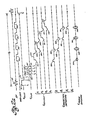
- the general form of RF/gradient pulse sequence for obtaining multiple-view multiple-readout data sets is shown in Figure 2a.
- the general sequence requires that the pair of flow-encoding gradient pulses be applied immediately after the single RF pulse of the sequence, with each of the plurality of subsequent multiple echoes being obtained with a different readout gradient orientation.
- each readout gradient field pulse may be preceded by a dephasing pulse portion, so that the associated echo is caused to occur in the middle of the associated readout pulse; a rephasing pulse portion may then be applied after each readout gradient field pulse, to remove the phase shift accumulated during the generation of the associated echo.
- a phase-invariant RF signal pulse 20 is initially applied to the sample to nutate the spins through 90°.
- the ⁇ /2 RF pulse 20 is generally not made volume selective; however, pulse 20 can be made slice-selective, to limit the excited sample volume, by the presence of a slice-selective gradient G SLICE portion 21, occurring over at least the same time interval (from time t0 to time t1) as pulse 20.
- RF pulse 20 can be, for example, of the sin(x)/x form, and can be truncated to include a specific odd number of lobes, e.g. 5, to substantially sharpen the excited volume limits.
- an associated rephasing portion 22, in the time interval from time t1 to time t2, may be advantageously used.
- the flow-encoding gradient G FLOW is provided with a first pulse 24, having a time duration T g (from time t3 to time t4), a first polarity and a first amplitude A, and then with a second pulse 25, having a second time duration T ⁇ g (from time t5 to time t6), a second polarity (opposite to the first polarity) and a second amplitude A ⁇ ; the midpoints of pulses 24 and 25 are separated by the interpulse time interval T.
- the selected sequence pair utilizes a first sequence with a positive polarity first pulse 24 and a negative polarity second pulse 25 (the pulses, shown in broken line, of the second sequence, of the sequence pair, have a negative polarity first pulse 24 ⁇ and a positive polarity second pulse 25 ⁇ , such that the second sequence pulses are inverted with respect to the polarities of the first sequence pulses); advantageously, both pulses 24 and 25 (and pulses 24 ⁇ and 25 ⁇ ) have the same amplitude
- and substantially equal time duration T g T ⁇ g .
- the phase-encoding gradient G PHASE-ENCODING pulse 30 is applied substantially simultaneously with the dephasing readout gradient G READOUT portion 31; the effect of each pulse 31 on spin phase is subsequently substantially cancelled by the effect of an associated inverted-polarity rephasing readout gradient portion 35.
- a projection-dephasing gradient pulses 32 is utilized to limit the dynamic range of the detected signal; the effect of each pulse 32 on spin phase is subsequently substantially cancelled by the effect of an associated inverted-polarity rephasing projection gradient pulse 36.
- each phase-encoding gradient pulse 30b, 30d,...of an even-numbered echo is inverted, wtih respect to the polarity of an odd-echo phase-encoding gradient pulse 30a, 30c,..., to cancel velocity-induced phase shifts arising from the pair of phase-encoding gradients.
- the phase encoding gradient portion 30a (having one of the plurality of phase-encoding values, in manner well known to the art) is provided substantially simultaneously with a first readout gradient portion dephasing portion 31a (in the direction of angle ⁇ 1) and a first projection dephasing gradient pulse 32a (in the direction of complement angle ⁇ 1, orthogonal to angle ⁇ 1).
- the data gate is opened (in portion 33a) in the presence of a first readout-encoding gradient portion 34a, for acquisition of first readout interval NMR response data.
- the data gate then closes.
- a first readout gradient rephasing pulse portion 35a occurs to rephase spin magnetization; the rephasing readout pulse portion 35a occurs substantially simultaneously with a first inverted-polarity projection dephasing pulse potion 36a, applied along the first complementary axis ⁇ 1 to cancel the spin dephasing effect caused by the initial projection dephasing pulse 32a.
- the inverted phase-encoding gradient portion which is required at the same time as pulses 35a and 36a, is not individually shown, as this pulse, with a now-negative polarity, is added to the inverted-polarity (e.g. now-negative polarity) phase-encoding gradient portion at the beginning of the even-numbered second readout interval, to form the double-amplitude phase-encoding pulse 30b. That is, the inverted phase-encoding pulse portion at the end of one readout time interval is of the same polarity as the initial pulse portion at the beginning of the next readout time interval (since the phase-encoding gradient polarity is alternated for alternating echoes), so that phase-encoding pulse 30b is of double negative amplitude.
- a second projection angle ⁇ 2 gradient readout dephasing pulse portion 31b occurs, along with a second projection-dephasing pulse portion 32b. It will thus be seen that the termination pulse portions at the end of one readout are made to overlap with the preparatory pulse portions at the commencement of the next echo readout; this temporal overlap allows even greater numbers of different view readouts to sequentially occur at the end of each sequence, in the time remaining before a next cardiac cycle triggers a next sequence.
- the second NMR echo signal data is (1) encoded by readout gradient portion 34b, (2) received a short time after the termination of pulse portions 30b, 31b and 32b, and (3) then acquired during data-gate-enabled portion 33b.
- the second view readout is terminated with the substantially simultaneous rephasing gradient pulse portions 35b and 36b, and half of a now-positive-polarity phase-encoding gradient portion 30c.
- the third multiple view echo readout portion commences with the other positive-polarity half of the phase-encoding pulse portion 30c, the readout gradient dephasing portion 31c and projection dephasing pulse 32c.
- the third view readout, encoded to angle ⁇ 3 by readout gradient portion 34c, is acquired during gate portion 33c, and is then terminated with rephasing pulse portions 35c and 36c and half of phase-encoding pulse 30d. This procedure continues for as many additional echoes as are necessary, each for providing data in the associate different view.
- the fourth, and final, view echo readout is prepared for by a phase-encoding pulse portion 30d, a readout dephasing pulse portion 31d and the associated one-half of the projection-dephasing pulse portion 30d.
- the fourth view data is acquired during data gate enablement portion 33d, while fourth ( ⁇ 4) readout gradient portion 34d is presented.
- the sequence ends after acquiring the last echo data during the last data gate enabled portion 33d, responsive to the last echo readout gradient portion 34d. Because no data from an additional view is to be taken, no additional readout rephasing pulse portion 35 or inverted-polarity projection dephasing pulse portion 36 is necessary.
- the second sequence of the pair is substantially similar, with only the inversion of the flow-encoding pulses 24 ⁇ and 25 ⁇ being different from the characteristics of the first sequence.
- the readout gradient orientation angle ⁇ i , the projection dephasing gradient orientation ⁇ i and the phase-encoding direction are all mutually orthogonal.
- the orientation of the phase-encoding gradient for each echo can be changed in the same manner as the orientation of the readout gradient for that echo.
- the dephasing lobe for each echo includes a readout (R) dephasing portion and a projection (P) dephasing portion.
- Each sequence, of a sequence pair begins with a slice-selective portion G s , (corresponding to the G SLICE portion in Figure 2a) comprising (a) the 90° RF pulse 20 ⁇ , and its slice-selective Z-axis gradient G Z portion 21 ⁇ , in the interval from time t0 to time t1, and (b) slice-selective rephasing gradient portion 22 ⁇ in the interval from time t1 to time t2.
- the flow encoding portion G f corresponding to the G FLOW portion of Figure 2a, occurs in the Z-axis gradient G Z with a first, positive-polarity pulse 24a being provided with amplitude +A and time duration T g (between time t3 and time t4) and a negative-polarity pulse 25a, of amplitude -A being provided in the time interval T g from time t5 to t6.
- the temporal midpoints of pulses 24a and 25a are separated by the interpulse time interval T.
- phase-encoding gradient pulses 37a-37d is utilized in each echo acquisition time interval T1-T4, at that one of the plurality of values to be utilized for that pair of sequences.
- the Y-axis and X-axis readout gradient portions 40a and 41a (the latter here having a zero amplitude) occur, to encode the first sequence, first projection readout data.
- the data gate enable signal 42a is present, and the first projection NMR response echo signal 43a is acquired and processed.
- the readout dephasing pulse portions 38b and 39b occur in the respective G Y and G X gradients, along with the next phase-encoding pulse 37b (of double amplitude and inverted polarity, in the time interval from time t b2 to time t c2 .
- the Y-axis and X-axis readout gradient portions 40a and 41a occur, from time t d2 to time t e2 , to encode the first sequence, second projection readout data.
- the data gate enable signal 42b is present, and the second projection NMR response echo signals 43b is acquired and processed.
- the phase-encoding pulse 37c and the readout dephasing pulse portions 38c and 39c occur in the respective G Y and G X gradients in the time interval from time t b3 to time t c3 .
- the Y-axis and X-axis readout gradient portions 40c and 41c occur, to encode the first sequence, third projection readout data.
- the data gate enable signal 42c is present, and the third projection NMR response echo signal 43c is acquired and processed.
- the phase-encoding pulse 37d and the readout dephasing pulse portions 38d and 39d (the former readout-dephasing portion here being of zero amplitude) occur in the respective G Y and G X gradients in the time interval from time t b4 to time t c4 .
- the Y-axis and X-axis readout gradient portions 40d and 41d (the former here having a zero amplitude) occur, to encode the first sequence, fourth projection readout data.
- the data gate enable signal 42d is present, and the fourth projection NMR response echo signal 43d is acquired and processed.
- the flow-encoding pulses 24 ⁇ a (negative polarity, amplitude A) occurs prior to the positive-polarity, A-amplitude pulse 25 ⁇ a.
- the same "stripe"-encoding values of lobes 37 are present, and all of the same lobes 38 and 40, in the G Y gradient, and lobes 39 and 41, in the G X gradient, occur.
- the patient's pulse rate of 60-120 beats-per-minute, gives rise to a repetition time interval T R of between about 0.5 seconds and about 1.0 seconds.
- view sampling time intervals T n on the order of 5 milliseconds typically allow data for up to 10 different views to be obtained, even though the T*2 of the flowing blood, over this total interval, may cause some degradation of later view quality.
- the view angle ⁇ n is not changed for each echo and the readout dephasing portions 46a-46d (for G y ) are all of equal amplitude, as are portions 47a-47d (for G x ), and each set of the readout gradients 48a-48d and 49a-49d are of one amplitude and like polarity.
- the projection dephasing lobe for the j-th echo can be substantially cancelled by the projection rephasing lobe for the (j-1)-th echo.
- the readout dephasing lobe of the j-th echo and the readout rephasing lobe for the (j-1)-th echo add constructively.
- each of the multiplicity (e.g. 128 or 256) of sequence pairs, for each of the pair of angiograms could have been either sequentially acquired (acquire all of the required, e.g.
- the first image might be acquired with flow sensitivity in the readout direction (e.g.
- This sequence acquires both the A and B direction flow-sensitive echoes in the single sequence pair for each one of the required (e.g. 128 or 256) total "stripes" for the total image, rather than requiring two pairs of sequences for each stripe.
- the data for each of a pair of angiograms, orthogonal to one another as required for displaying a total flow angiogram is acquired in interleaved manner in each one of a pair of readout time intervals during each imaging sequence of each angiographic sequence pair.
- the flow-encoding gradient applied for the first echo is followed, after the readout of the first echo response data, by a pair of flow-encoding gradients having inverted polarity respective to the first flow-encoding gradient.
- One of the pair of second gradients has an inverted-polarity second flow-encoding gradient pulse pair, in the first gradient direction, to remove the velocity-induced phase shift created by the first flow-encoding gradient pulse pair.
- the other pair of flow-encoding gradient pulses are applied in a second flow-encoding direction essentially orthogonal to the direction of the first pair.
- the first flow gradient may be applied in the Z-axis direction and the second flow gradient applied in the X-axis direction.
- the two interleaved acquired echoes are independently processed to obtain the flow component angiogram intensity sets, which are then combined utilizing equation 6. It will be seen that phase shift between the first and second echo angiograms, due to resonance offsets and the like, are not important, as it is only the magnitude of each angiogram which are added.
- the T2* signal intensity differences of the echo pair will be relatively small.
- the sequence can be extended to add a third echo, or even a fourth echo, which can be processed and compared to the processed echoes from the first and/or second echoes to derive factors useful to correct for the T2* intensity decay.
- the general form of RF/gradient pulse sequence for obtaining simultaneous acquisition of orthogonal flow direction images is shown in Figure 3a.
- the nutative 90° RF signal pulse 20, either with slice-selective gradient lobe 21 and rephasing lobe 22, or without slice-selective gradient (as desired), occurs in the expected time intervals between the times t0 and time t2.
- the first pair of flow-encoding gradient pulses 24a and 25a occurs between time t3 and time t6; thereafter, the first readout time interval commences with a preceding dephasing pulse portion 55a, substantially simultaneous with a projection-dephasing gradient pulse lobe 56 and the first phase-encoding gradient pulse lobe 37 ⁇ a.
- the associated echo caused to occur in the middle of the first readout time interval, when associated readout gradient pulse portion 57a is present, is received during the data gate enabled portion 59a. Thereafter, the readout gradient is provided with a rephasing pulse 60 to remove the phase shift accumulated during the generation of the first echo; the readout time interval ends at the termination of pulse 60.
- An inverted-polarity phase-encoding gradient lobe 37 ⁇ b appears substantially simultaneous with rephasing lobe 60, to correct for the phase shift provided in the phase-encoding direction due to pulse 37 ⁇ a.
- the effect of the first flow-encoding gradient pair of pulses 24a-25a is phase compensated for by a second flow-encoding pulse pair, with reversed polarity, in the first flow gradient.
- This pair of pulses 24b and 25b (or inverted polarity pulses 24 ⁇ b and 25 ⁇ b in the second sequence of the sequence pair), respectively occur with the same time interval T g (respectively between times t ⁇ 3 and t ⁇ 4 or between times t ⁇ 5 and t ⁇ 6), and with an interpulse time interval T ⁇ substantially equal to the first pulse-pair interval T.
- a pair of flow-enocding pulses is provided in the second, orthogonal gradient G FLOW2 ; the polarity of this pair of pulses is the same as the polarity of the first flow encoding pulses 24a and 25a (or 24 ⁇ a and 25 ⁇ a) in the first flow encoding gradient direction-i.e. a first positive polarity pulse 62 followed by a negative-polarity pulse 64 in the first sequence (or a negative-polarity pulse 62 ⁇ followed by a positive polarity pulse 64 ⁇ , in the second sequence of the sequence pair).
- the second echo readout is prepared for with the occurrence of a preceding dephasing pulse lobe 55b.
- the orthogonal flow direction data, encoded in the readout direction by readout gradient portion 58b, is acquired during data gate enable portion 59b.
- the entire sequence has been repeated with inverted flow-encoding pulses (e.g. pulses 24 ⁇ a/25 ⁇ a, 24 ⁇ b/25 ⁇ b and 62 ⁇ /64 ⁇ )
- the data from the first echo of the first sequence is subtracted from the data from the first echo of the second sequence to derive the first-direction image data.
- the data from the second echo of the first sequence is subtracted from the data for the second echo of the second sequence to provide the data set for the orthogonal-direction image.
- the first-direction-selective (e.g., Z-direction) flow-encoding set of gradient pulses G fz includes a first negative-polarity pulse 66a, between times t3 and t4, and a second positive-polarity pulse 68a, between times t5 and t6.
- the phase-encoding gradient G pe portion commences with the associated multi-valued one of the gradient pulses 70a for that one of the multiplicity of stripes in the sequence-pair data subset.
- the readout dephasing pulse 72a is provided, along with the dynamic-range-limiting projection-dephasing pulse 74 in the G X signal.
- the Y-direction readout gradient portion 76a is present from time t9 to time t a , during which time interval the data gate 78a is enabled and a received response signal 80a is acquired, digitized and processed as required by a particular system.
- the rephasing pulse 82 in the readout gradient G Y commences at time t b and terminates at time t c , as does the inverted-polarity phase-encoding-cancelling pulse 70b.
- the pair of first direction (Z-direction) cancelling pulses 66b and 68b occurs, for a cancelling gradient G -fz , in the time interval between time t d and t g , while the second direction (Y-direction) flow-encoding pulses 86 and 88 (for second flow gradient G fy ) occur substantially simultaneously therewith.
- new phase-encoding pulse 70c occurs substantially simultaneous with the Y-axis readout preliminary dephasing pulse 72b, in the time interval from time t h to time t i .
- the readout gradient portion 76b is present, and the data gate 78b is open to receive the second, Y-directed received response signal 80b, in direction orthogonal to the Z-direction of the first response signal 80a.
- the Z and Y projection data sets are Fourier-transformed, subjected to the operations of equation 6 and stored, as a total angiogram data set, for display as required.
- the illustrated high-suppression sequence has (a) zero-amplitude portions 84a and 84b appearing before the first readout data gate 78a in both of the first and second sequences of each sequence pair, and (b) a positive-polarity first pulse 66b and a negative-polarity second pulse 68b between the first and second data gates in the first sequence or a negative-polarity pulse 66c (broken-line) and a positive-polarity pulse 68c (broken line) between the first and second data gates in the second sequence, of each sequence pair, to provide a gradient-refocussed spin-warp sequence where both echoes are taken with the same view angle.
- the second and third dephasing gradient pulses 86 and 88 can be eliminated if the second readout gradient pulse 76b is provided as an inverted-polarity pulse 76c. It will also be understood that similar utility can be found for a sequence pair with the first sequence having first flow-encoding pulses 66d/68d and second flow-encoding pulses 66c/68c, and the second sequence having first flow-encoding pulses 68a/68a and second flow-encoding pulses 66b/66b.
- another degenerative case utilizes the additive nature of the phase changes in the response signals, induced by flow and flow-encoding gradient pulses, to provide a set of image data for each of a plurality of different velocity ranges without the necessity for separately acquiring each range in a separate set of sequence pairs.
- one of N identical pairs of flow-encoding gradient pulses occur before each of N different-range echoes; the total phase change is additive, such that the total phase change in the N-th echo, after the N-th pulse pair, is N times as greater as the phase change in the first echo, or the same flow velocity.
- the detected velocity is decreased by a factor N, for the N-th echo.
- the N-th echo phase shift ⁇ N for the V1 velocity is N ⁇ 1 and the flow velocity for the basic phase amount ⁇ 1 is V1/N.
- Respective third,..., N-th pairs of initially-positive-polarity and subsequent negative-polarity pulses can be used for acquiring third,..., N-th echoes.
- the first pair of pulses consists of negative-polarity pulse 66a and positive-polarity pulse 68a, while the second pair consists of negative pulse 66c and positive pulse 68c, etc.
- N images are acquired, with each later image being sensitive to a different, slower flow velocity. If the image data sets are Fourier transformed in the "third dimension" (i.e., as a function of response echo signal number N), then a true velocity selective angiogram will result.
- the projection-dephasing gradient can be removed if phase cancellation of the desired response signals appears to be occuring because of the physical location of the involved vessels; the artifact so occurring is reasonably easy to recognize.
Landscapes
- Physics & Mathematics (AREA)
- Health & Medical Sciences (AREA)
- Nuclear Medicine, Radiotherapy & Molecular Imaging (AREA)
- Signal Processing (AREA)
- Radiology & Medical Imaging (AREA)
- Engineering & Computer Science (AREA)
- General Health & Medical Sciences (AREA)
- Vascular Medicine (AREA)
- High Energy & Nuclear Physics (AREA)
- Condensed Matter Physics & Semiconductors (AREA)
- General Physics & Mathematics (AREA)
- Magnetic Resonance Imaging Apparatus (AREA)
- Measuring Volume Flow (AREA)
Applications Claiming Priority (2)
| Application Number | Priority Date | Filing Date | Title |
|---|---|---|---|
| US07/013,592 US4796635A (en) | 1987-02-11 | 1987-02-11 | Multiple-echo, multiple-view NMR angiography |
| US13592 | 1998-01-26 |
Publications (2)
| Publication Number | Publication Date |
|---|---|
| EP0278271A2 true EP0278271A2 (de) | 1988-08-17 |
| EP0278271A3 EP0278271A3 (de) | 1990-06-13 |
Family
ID=21760727
Family Applications (1)
| Application Number | Title | Priority Date | Filing Date |
|---|---|---|---|
| EP88100760A Ceased EP0278271A3 (de) | 1987-02-11 | 1988-01-20 | Vielfach-Echo-NMR-Angiographie |
Country Status (5)
| Country | Link |
|---|---|
| US (1) | US4796635A (de) |
| EP (1) | EP0278271A3 (de) |
| JP (1) | JPS63226343A (de) |
| FI (1) | FI880585A7 (de) |
| IL (1) | IL85126A (de) |
Cited By (2)
| Publication number | Priority date | Publication date | Assignee | Title |
|---|---|---|---|---|
| AT399646B (de) * | 1989-12-01 | 1995-06-26 | Wach Paul Dipl Ing Dr Techn | Einrichtung zur erfassung des durchflusses des blutgefässsystems |
| DE4432575C2 (de) * | 1993-09-14 | 2003-04-10 | Toshiba Kawasaki Kk | Verfahren zur Bildgebung der Gehirnfunktion mittels einer Kernspinresonanz-Vorrichtung und hieran angepasste Kernspinresonanz-Vorrichtung |
Families Citing this family (32)
| Publication number | Priority date | Publication date | Assignee | Title |
|---|---|---|---|---|
| US5022397A (en) * | 1987-02-11 | 1991-06-11 | General Electric Company | Multiple-echo NMR angiography with multiple-velocity images |
| US5022398A (en) * | 1987-02-11 | 1991-06-11 | General Electric Company | Multiple-echo NMR angiography for enhancement of signal-to noise ratio |
| US5025788A (en) * | 1987-02-11 | 1991-06-25 | General Electric Company | Method of acquiring NMR angiograms in selected flow component directions |
| DE3726932A1 (de) * | 1987-08-13 | 1989-02-23 | Spectrospin Ag | Verfahren zum kodieren von n parametern bei der mehrdimensionalen fourier-nmr-spektroskopie |
| US4978918A (en) * | 1988-04-24 | 1990-12-18 | Mitsubishi Denki Kabushiki Kaisha | Magnetic resonance imaging method |
| DE3823961A1 (de) * | 1988-07-15 | 1990-01-18 | Philips Patentverwaltung | Kernspintomographieverfahren und kernspintomograph zur durchfuehrung des verfahrens |
| JPH0685769B2 (ja) * | 1988-09-09 | 1994-11-02 | 富士電機株式会社 | 磁気共鳴イメージング装置 |
| US4952876A (en) * | 1988-11-23 | 1990-08-28 | General Electric Company | Variable bandwidth multiecho NMR imaging |
| US5115812A (en) * | 1988-11-30 | 1992-05-26 | Hitachi, Ltd. | Magnetic resonance imaging method for moving object |
| US4918386A (en) * | 1988-12-23 | 1990-04-17 | General Electric Company | Method for simultaneously obtaining three-dimensional NMR angiograms and stationary tissue NMR images |
| US4888552A (en) * | 1989-01-05 | 1989-12-19 | Elscint Ltd. | Magnetic resonance imaging |
| DE4024161A1 (de) * | 1989-08-11 | 1991-02-14 | Siemens Ag | Pulssequenz zur schnellen ermittlung von bildern der fett- und wasserverteilung in einem untersuchungsobjekt mittels der kernmagnetischen resonanz |
| US4973906A (en) * | 1989-08-17 | 1990-11-27 | General Electric Company | Flow compensated NMR fast pulse sequence |
| JPH03228745A (ja) * | 1990-02-05 | 1991-10-09 | Toshiba Corp | Mri装置 |
| EP0447970B1 (de) * | 1990-03-20 | 1997-09-10 | Kabushiki Kaisha Toshiba | Verfahren und Apparat zur Bilderzeugung von Blutgefässen mittels magnetischer Resonanz |
| US5221898A (en) * | 1990-11-30 | 1993-06-22 | Hitachi, Ltd. | Flow imaging method using an MRI apparatus |
| US5133357A (en) * | 1991-02-07 | 1992-07-28 | General Electric Company | Quantitative measurement of blood flow using cylindrically localized fourier velocity encoding |
| JP3161750B2 (ja) * | 1991-06-05 | 2001-04-25 | 株式会社日立製作所 | 磁気共鳴診断装置および画像データ処理方法 |
| US5233302A (en) * | 1991-06-21 | 1993-08-03 | General Electric Company | Masking motion ghost artifacts in NMR images |
| US5270654A (en) * | 1991-07-05 | 1993-12-14 | Feinberg David A | Ultra-fast multi-section MRI using gradient and spin echo (grase) imaging |
| US5281914A (en) * | 1991-08-09 | 1994-01-25 | The Johns Hopkins University | Method of vector magnetic resonance measurement and imaging and associated apparatus |
| US5233298A (en) * | 1992-02-20 | 1993-08-03 | General Electric Company | Quantitative measurement of blood flow at multiple positions using comb excitation and fourier velocity encoding |
| US5277192A (en) * | 1992-09-18 | 1994-01-11 | General Electric Company | Imaging of turbulence with magnetic resonance |
| US6122540A (en) * | 1994-06-08 | 2000-09-19 | The Regents Of The University Of California | Noninvasive measurement of renal hemodynamic functions using magnetic resonance imaging |
| US5602891A (en) * | 1995-11-13 | 1997-02-11 | Beth Israel | Imaging apparatus and method with compensation for object motion |
| US6188922B1 (en) * | 1999-01-08 | 2001-02-13 | Wisconsin Alumni Research Foundation | Phase contrast imaging using interleaved projection data |
| WO2002067202A1 (en) | 2001-02-16 | 2002-08-29 | The Government Of The United States Of America, Represented By The Secretary, Department Of Health And Human Services | Real-time, interactive volumetric mri |
| JP4309632B2 (ja) * | 2002-10-08 | 2009-08-05 | 株式会社東芝 | 磁気共鳴イメージング装置 |
| US7646198B2 (en) * | 2007-03-09 | 2010-01-12 | Case Western Reserve University | Methods for fat signal suppression in magnetic resonance imaging |
| WO2009094304A2 (en) * | 2008-01-23 | 2009-07-30 | The Regents Of The University Of Colorado | Susceptibility weighted magnetic resonance imaging of venous vasculature |
| KR101253024B1 (ko) * | 2011-05-06 | 2013-04-16 | 연세대학교 산학협력단 | 자기공명영상을 이용한 삼차원 영상 복원장치 및 방법 |
| US11191503B2 (en) | 2018-07-17 | 2021-12-07 | International Business Machines Corporation | Fluid-injector for a simultaneous anatomical and fluid dynamic analysis in coronary angiography |
Citations (2)
| Publication number | Priority date | Publication date | Assignee | Title |
|---|---|---|---|---|
| EP0191431A2 (de) | 1985-02-12 | 1986-08-20 | Max-Planck-Gesellschaft zur Förderung der Wissenschaften e.V. | Verfahren und Einrichtung zur schnellen Akquisition von Spinresonanzdaten für eine ortsaufgelöste Untersuchung eines Objekts |
| US4714081A (en) | 1986-03-03 | 1987-12-22 | General Electric Company | Methods for NMR angiography |
Family Cites Families (9)
| Publication number | Priority date | Publication date | Assignee | Title |
|---|---|---|---|---|
| US4458203A (en) * | 1980-12-11 | 1984-07-03 | Picker International Limited | Nuclear magnetic resonance imaging |
| US4528985A (en) * | 1981-12-21 | 1985-07-16 | Albert Macovski | Blood vessel imaging system using nuclear magnetic resonance |
| US4443760A (en) * | 1982-07-01 | 1984-04-17 | General Electric Company | Use of phase alternated RF pulses to eliminate effects of spurious free induction decay caused by imperfect 180 degree RF pulses in NMR imaging |
| JPS5940843A (ja) * | 1982-08-31 | 1984-03-06 | 株式会社東芝 | 診断用核磁気共鳴装置 |
| US4602641A (en) * | 1983-08-15 | 1986-07-29 | The Regents Of The University Of California | Method and apparatus for NMR detection and imaging of flowing fluid nuclei |
| US4595879A (en) * | 1983-11-14 | 1986-06-17 | Technicare Corporation | Nuclear magnetic resonance flow imaging |
| US4609872A (en) * | 1984-08-10 | 1986-09-02 | General Electric Company | NMR multiple-echo phase-contrast blood flow imaging |
| US4625169A (en) * | 1984-08-10 | 1986-11-25 | The General Hospital Corporation | Flow imaging by means of nuclear magnetic resonance |
| US4654591A (en) * | 1985-07-29 | 1987-03-31 | Wisconsin Alumni Research Foundation | NMR flow imaging using bi-phasic excitation field gradients |
-
1987
- 1987-02-11 US US07/013,592 patent/US4796635A/en not_active Expired - Fee Related
-
1988
- 1988-01-19 IL IL8512688A patent/IL85126A/en not_active IP Right Cessation
- 1988-01-20 EP EP88100760A patent/EP0278271A3/de not_active Ceased
- 1988-02-09 FI FI880585A patent/FI880585A7/fi not_active IP Right Cessation
- 1988-02-10 JP JP63027838A patent/JPS63226343A/ja active Granted
Patent Citations (2)
| Publication number | Priority date | Publication date | Assignee | Title |
|---|---|---|---|---|
| EP0191431A2 (de) | 1985-02-12 | 1986-08-20 | Max-Planck-Gesellschaft zur Förderung der Wissenschaften e.V. | Verfahren und Einrichtung zur schnellen Akquisition von Spinresonanzdaten für eine ortsaufgelöste Untersuchung eines Objekts |
| US4714081A (en) | 1986-03-03 | 1987-12-22 | General Electric Company | Methods for NMR angiography |
Non-Patent Citations (8)
| Title |
|---|
| C.L.DUMOULIN ET AL., MAGNETIC RESONANCE ANGIOGRAPHY, pages 717 - 720 |
| D.G. NISHIMURA ET AL.: "IEEE Transactions on Medical Imaging", MAGNETIC RESONANCE ANGIOGRAPHY, vol. MI-5, no. 3, September 1986 (1986-09-01), pages 140 - 151 |
| D.G. NISHIMURA ET AL.: "Magnetic Resonance Angiography", IEEE TRANSACTIONS ON MEDICAL IMAGING, vol. MI-5, no. 3, September 1986 (1986-09-01), pages 140 - 151 |
| M.O'DONNELL: "NMR blood flow imaging using multiecho, phase contrast sequences", MEDICAL PHYSICS, vol. 12, no. 1, February 1985 (1985-02-01), pages 59 - 64 |
| P.R.MORAN ET AL., VERIFICATION AND EVALUATION OF INTERNAL FLOW AND MOTION, pages 433 - 441 |
| PROCEEDINGS OF THE IEEE, vol. 70, no. 10, October 1982 (1982-10-01) |
| RADIOLOGY, vol. 154, February 1985 (1985-02-01) |
| Z.H. CHO ET AL., FOURIER TRANSFORM NUCLEAR MAGNETIC RESONANCE TOMOGRAPHIC IMAGING, pages 11152 - 11173 |
Cited By (2)
| Publication number | Priority date | Publication date | Assignee | Title |
|---|---|---|---|---|
| AT399646B (de) * | 1989-12-01 | 1995-06-26 | Wach Paul Dipl Ing Dr Techn | Einrichtung zur erfassung des durchflusses des blutgefässsystems |
| DE4432575C2 (de) * | 1993-09-14 | 2003-04-10 | Toshiba Kawasaki Kk | Verfahren zur Bildgebung der Gehirnfunktion mittels einer Kernspinresonanz-Vorrichtung und hieran angepasste Kernspinresonanz-Vorrichtung |
Also Published As
| Publication number | Publication date |
|---|---|
| JPS63226343A (ja) | 1988-09-21 |
| IL85126A0 (en) | 1988-06-30 |
| JPH0424051B2 (de) | 1992-04-24 |
| EP0278271A3 (de) | 1990-06-13 |
| FI880585A7 (fi) | 1988-08-12 |
| IL85126A (en) | 1996-06-18 |
| FI880585A0 (fi) | 1988-02-09 |
| US4796635A (en) | 1989-01-10 |
Similar Documents
| Publication | Publication Date | Title |
|---|---|---|
| US4796635A (en) | Multiple-echo, multiple-view NMR angiography | |
| US4714081A (en) | Methods for NMR angiography | |
| EP0285862B1 (de) | Schnelles NMR Angiographieverfahren | |
| US5133357A (en) | Quantitative measurement of blood flow using cylindrically localized fourier velocity encoding | |
| US5038783A (en) | Multiple gradient echo pulse sequence for acquisition of NMR angiograms | |
| US7706857B2 (en) | Methods and apparatus for mapping internal and bulk motion of an object with phase labeling in magnetic resonance imaging | |
| EP2699926B1 (de) | Räumlich kodierte phasenkontrast-mri | |
| US5038784A (en) | Multiple-echo angiography with enhanced signal-to-noise ratio | |
| US5051699A (en) | Magnetic resonance imaging system | |
| US5022397A (en) | Multiple-echo NMR angiography with multiple-velocity images | |
| US5653233A (en) | Method and apparatus for improved temporal resolution in dynamic MRI | |
| US4918386A (en) | Method for simultaneously obtaining three-dimensional NMR angiograms and stationary tissue NMR images | |
| WO2005111647A1 (en) | Contrast prepared mri involving non-cartesian trajectories with oversampling of the center of k-space | |
| EP0835454B1 (de) | Echoplanar-Bildgebung mit Verschiebung der Echozeit und Bewegungskompensation | |
| US7233818B1 (en) | Methods and apparatus for mapping internal and bulk motion of an object with phase labeling in magnetic resonance imaging | |
| Dumoulin et al. | Multiecho magnetic resonance angiography | |
| US7368910B2 (en) | Dual gradient echo pulse sequence using interleaved spiral-out spiral-in k-space trajectories | |
| US5025788A (en) | Method of acquiring NMR angiograms in selected flow component directions | |
| US5541512A (en) | Method for the prevention of registration artifacts due to motion in magnetic resonance images | |
| US5022398A (en) | Multiple-echo NMR angiography for enhancement of signal-to noise ratio | |
| US4855679A (en) | Magnetic resonance studies of restricted volumes | |
| US20210270918A1 (en) | Method for generating a magnetic resonance image | |
| EP4097498B1 (de) | Mrt-bildgebung unter verwendung einer wasser/fett-trennung nach dixon mit unterdrückung von strömungsinduzierter leckage und/oder vertauschungs-artefakten | |
| KR930000103B1 (ko) | 핵 자기 공명 혈관 조영 영상 획득 장치 | |
| US20070268019A1 (en) | Imaging Procedure and Magnetic-Resonance Imaging System for the Acquistion of the Longitudinal Spin-Lattice Relaxation Time |
Legal Events
| Date | Code | Title | Description |
|---|---|---|---|
| PUAI | Public reference made under article 153(3) epc to a published international application that has entered the european phase |
Free format text: ORIGINAL CODE: 0009012 |
|
| AK | Designated contracting states |
Kind code of ref document: A2 Designated state(s): CH DE FR GB IT LI NL SE |
|
| PUAL | Search report despatched |
Free format text: ORIGINAL CODE: 0009013 |
|
| AK | Designated contracting states |
Kind code of ref document: A3 Designated state(s): CH DE FR GB IT LI NL SE |
|
| 17P | Request for examination filed |
Effective date: 19901126 |
|
| 17Q | First examination report despatched |
Effective date: 19921013 |
|
| GRAG | Despatch of communication of intention to grant |
Free format text: ORIGINAL CODE: EPIDOS AGRA |
|
| STAA | Information on the status of an ep patent application or granted ep patent |
Free format text: STATUS: THE APPLICATION HAS BEEN REFUSED |
|
| 18R | Application refused |
Effective date: 19961204 |