EP0278362A2 - Verfahren und Vorrichtung zum Herstellen formhaltigen Halbzeugs aus Thermoplast enthaltendem Bindemittel sowie Halbzeug - Google Patents
Verfahren und Vorrichtung zum Herstellen formhaltigen Halbzeugs aus Thermoplast enthaltendem Bindemittel sowie Halbzeug Download PDFInfo
- Publication number
- EP0278362A2 EP0278362A2 EP88101444A EP88101444A EP0278362A2 EP 0278362 A2 EP0278362 A2 EP 0278362A2 EP 88101444 A EP88101444 A EP 88101444A EP 88101444 A EP88101444 A EP 88101444A EP 0278362 A2 EP0278362 A2 EP 0278362A2
- Authority
- EP
- European Patent Office
- Prior art keywords
- compression
- melting
- channel
- semi
- thermoplastic
- Prior art date
- Legal status (The legal status is an assumption and is not a legal conclusion. Google has not performed a legal analysis and makes no representation as to the accuracy of the status listed.)
- Granted
Links
Images

Classifications
-
- B—PERFORMING OPERATIONS; TRANSPORTING
- B29—WORKING OF PLASTICS; WORKING OF SUBSTANCES IN A PLASTIC STATE IN GENERAL
- B29B—PREPARATION OR PRETREATMENT OF THE MATERIAL TO BE SHAPED; MAKING GRANULES OR PREFORMS; RECOVERY OF PLASTICS OR OTHER CONSTITUENTS OF WASTE MATERIAL CONTAINING PLASTICS
- B29B13/00—Conditioning or physical treatment of the material to be shaped
- B29B13/02—Conditioning or physical treatment of the material to be shaped by heating
-
- B—PERFORMING OPERATIONS; TRANSPORTING
- B29—WORKING OF PLASTICS; WORKING OF SUBSTANCES IN A PLASTIC STATE IN GENERAL
- B29B—PREPARATION OR PRETREATMENT OF THE MATERIAL TO BE SHAPED; MAKING GRANULES OR PREFORMS; RECOVERY OF PLASTICS OR OTHER CONSTITUENTS OF WASTE MATERIAL CONTAINING PLASTICS
- B29B11/00—Making preforms
- B29B11/14—Making preforms characterised by structure or composition
-
- B—PERFORMING OPERATIONS; TRANSPORTING
- B29—WORKING OF PLASTICS; WORKING OF SUBSTANCES IN A PLASTIC STATE IN GENERAL
- B29B—PREPARATION OR PRETREATMENT OF THE MATERIAL TO BE SHAPED; MAKING GRANULES OR PREFORMS; RECOVERY OF PLASTICS OR OTHER CONSTITUENTS OF WASTE MATERIAL CONTAINING PLASTICS
- B29B11/00—Making preforms
- B29B11/06—Making preforms by moulding the material
- B29B11/10—Extrusion moulding
-
- B—PERFORMING OPERATIONS; TRANSPORTING
- B29—WORKING OF PLASTICS; WORKING OF SUBSTANCES IN A PLASTIC STATE IN GENERAL
- B29C—SHAPING OR JOINING OF PLASTICS; SHAPING OF MATERIAL IN A PLASTIC STATE, NOT OTHERWISE PROVIDED FOR; AFTER-TREATMENT OF THE SHAPED PRODUCTS, e.g. REPAIRING
- B29C49/00—Blow-moulding, i.e. blowing a preform or parison to a desired shape within a mould; Apparatus therefor
- B29C49/071—Preforms or parisons characterised by their configuration, e.g. geometry, dimensions or physical properties
-
- B—PERFORMING OPERATIONS; TRANSPORTING
- B29—WORKING OF PLASTICS; WORKING OF SUBSTANCES IN A PLASTIC STATE IN GENERAL
- B29C—SHAPING OR JOINING OF PLASTICS; SHAPING OF MATERIAL IN A PLASTIC STATE, NOT OTHERWISE PROVIDED FOR; AFTER-TREATMENT OF THE SHAPED PRODUCTS, e.g. REPAIRING
- B29C2949/00—Indexing scheme relating to blow-moulding
- B29C2949/07—Preforms or parisons characterised by their configuration
- B29C2949/0715—Preforms or parisons characterised by their configuration the preform having one end closed
-
- Y—GENERAL TAGGING OF NEW TECHNOLOGICAL DEVELOPMENTS; GENERAL TAGGING OF CROSS-SECTIONAL TECHNOLOGIES SPANNING OVER SEVERAL SECTIONS OF THE IPC; TECHNICAL SUBJECTS COVERED BY FORMER USPC CROSS-REFERENCE ART COLLECTIONS [XRACs] AND DIGESTS
- Y10—TECHNICAL SUBJECTS COVERED BY FORMER USPC
- Y10T—TECHNICAL SUBJECTS COVERED BY FORMER US CLASSIFICATION
- Y10T428/00—Stock material or miscellaneous articles
- Y10T428/23—Sheet including cover or casing
- Y10T428/237—Noninterengaged fibered material encased [e.g., mat, batt, etc.]
-
- Y—GENERAL TAGGING OF NEW TECHNOLOGICAL DEVELOPMENTS; GENERAL TAGGING OF CROSS-SECTIONAL TECHNOLOGIES SPANNING OVER SEVERAL SECTIONS OF THE IPC; TECHNICAL SUBJECTS COVERED BY FORMER USPC CROSS-REFERENCE ART COLLECTIONS [XRACs] AND DIGESTS
- Y10—TECHNICAL SUBJECTS COVERED BY FORMER USPC
- Y10T—TECHNICAL SUBJECTS COVERED BY FORMER US CLASSIFICATION
- Y10T428/00—Stock material or miscellaneous articles
- Y10T428/29—Coated or structually defined flake, particle, cell, strand, strand portion, rod, filament, macroscopic fiber or mass thereof
- Y10T428/2913—Rod, strand, filament or fiber
-
- Y—GENERAL TAGGING OF NEW TECHNOLOGICAL DEVELOPMENTS; GENERAL TAGGING OF CROSS-SECTIONAL TECHNOLOGIES SPANNING OVER SEVERAL SECTIONS OF THE IPC; TECHNICAL SUBJECTS COVERED BY FORMER USPC CROSS-REFERENCE ART COLLECTIONS [XRACs] AND DIGESTS
- Y10—TECHNICAL SUBJECTS COVERED BY FORMER USPC
- Y10T—TECHNICAL SUBJECTS COVERED BY FORMER US CLASSIFICATION
- Y10T428/00—Stock material or miscellaneous articles
- Y10T428/29—Coated or structually defined flake, particle, cell, strand, strand portion, rod, filament, macroscopic fiber or mass thereof
- Y10T428/2913—Rod, strand, filament or fiber
- Y10T428/2933—Coated or with bond, impregnation or core
-
- Y—GENERAL TAGGING OF NEW TECHNOLOGICAL DEVELOPMENTS; GENERAL TAGGING OF CROSS-SECTIONAL TECHNOLOGIES SPANNING OVER SEVERAL SECTIONS OF THE IPC; TECHNICAL SUBJECTS COVERED BY FORMER USPC CROSS-REFERENCE ART COLLECTIONS [XRACs] AND DIGESTS
- Y10—TECHNICAL SUBJECTS COVERED BY FORMER USPC
- Y10T—TECHNICAL SUBJECTS COVERED BY FORMER US CLASSIFICATION
- Y10T442/00—Fabric [woven, knitted, or nonwoven textile or cloth, etc.]
- Y10T442/50—FELT FABRIC
Definitions
- the invention relates to a method and a device for producing semi-finished products made of fiber-reinforced thermoplastic and a semi-finished product made of fiber-reinforced thermoplastic.
- Cut glass fibers in particular, but also other mineral, inorganic or other artificial fibers, such as carbon fibers, aramid fibers or polyester fibers. Insofar as glass fibers are mentioned below, they can also be replaced by the aforementioned fibers. Cut glass fibers are used extensively for the manufacture of glass fiber reinforced plastic parts. The glass fibers are bound by a binder which, as the main constituent or matrix, has a thermoplastic such as polypropylene and can additionally have carbon black, wax and other additives and chemical couplers. In practice, the manufacture of semi-finished products that can be pressed into a molded part in a press takes place by spreading the fibers into a fleece and impregnating the same with liquid synthetic resin.
- a binder which, as the main constituent or matrix, has a thermoplastic such as polypropylene and can additionally have carbon black, wax and other additives and chemical couplers.
- the fibers are processed in the liquid phase to form a slurry, which is processed to a tangled fiber material by stirring or mixing movements.
- liquid synthetic resins or powdery binders are used in conjunction with an aqueous slurry.
- the slurry is dried after a non-woven fabric is formed.
- the thickness and width of the fleece must be adapted to the molded part to be molded, the former necessarily, the latter in order to avoid excessive waste. Furthermore, the fleece must then be cut into individual plates to match the molded parts to be produced.
- the object of the invention is to provide an easy-to-use, easily transportable and largely automatically processable semi-finished product which can be processed without great energy expenditure, in particular in such a way that the starting material does not have to be made dependent on the molded parts to be produced.
- a method which is characterized in that a pourable intermediate product consisting of fibers and thermoplastic binder is heated only in a thin jacket area above the melting temperature of the thermoplastic.
- a device according to the invention in particular for carrying out the method, is characterized in that a melting device with a melting channel, through which the material to be processed is pressed as an endless strand, is provided and a cooling device is connected to the melting device.
- a semi-finished product that meets the above requirements is characterized by a solid jacket made of fibers and thermoplastic that solidifies again after melting and a felt-like or cotton-like core made from a fiber-polymer mixture.
- the method according to the invention enables a simplification of the production process and a high degree of automation in the production of molded parts. No further processing of the semi-finished product is required for further processing. The investment costs can be kept low.
- a decomposition of the Thermoplastic matrix can be excluded by overheating, which reduces the risk of fire and increases environmental friendliness.
- the method according to the invention enables great variations in the use of higher-quality thermoplastics (for example PA, PTP) and the use of different reinforcing fibers.
- the semifinished product produced according to the invention can be preheated to below the melting point of the polymer or heated to above its melting point for further processing by inert hot gases or hot air blown through the felt or wadding-like core, which is not particularly energy-intensive when the heating gas is recirculated.
- the starting material can be supplied in a standard package size and does not have to be adapted to the specific insert weights etc. of the molded parts, as is required in the production of glass mats.
- a preferred embodiment of the invention provides that the cotton-like pre-product is pre-compressed and immediately Endless strand is supplied or that a compression station is connected directly upstream of the melting device, whereby according to a further development it can further be provided that the compression station has a cooled compression channel, to which the melting channel of the melting device is directly connected and that at the transition point from the compression channel and melting channel At the end of the compression channel, a compression and delivery piston is movably arranged, and in particular that the melting channel of the melting device is surrounded by heating elements over its entire length.
- vacuum is applied during the compression of the starting material in order to avoid air pockets and the like. You can do this
- vacuum lines via which the vacuum is applied can be provided.
- the melting channel is provided with heating elements over its entire length. The heating of the material in the melting channel takes place to a temperature which is higher than the melting temperature of the thermoplastic of the material and in particular is up to 100 ° C above the melting temperature.
- the method according to the invention allows a very high throughput of material to be softened, so a throughput of 2 kg or more per minute can be easily achieved.
- the wall of the melting channel is briefly heated by its heating elements above the melting point of the polymer of the starting product, so that the polymer melts only in a relatively thin shell area, but not in the inner core of the cotton fiber-polymer mass located in the channel. This is followed by cooling, so that the molten polymer solidifies again and plasticizes in the process. Rapid heating is essential, so that the polymer melts in the outer region without the high temperature being conducted into the core region and advantageously a subsequent likewise rapid cooling.
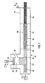
- the device 51 according to the invention for producing semi-finished products made of fiber-reinforced thermoplastic has a compression station 52, a melting channel 64 and a cooler station 54 on.
- the compression station 52 has a receiving and pre-compression chamber 56, into which a feed channel 57 opens and which is provided as a piston and cylinder unit 58 with a pre-compression piston 59.
- the piston 59 can be driven in a suitable manner, in particular hydraulically.
- the feed and precompression chamber 56 merges into a compression chamber 62.
- the compression chamber 62 has a compression and feed piston 63, which is also acted upon in a suitable manner, preferably hydraulically.
- a melting channel 64 of the melting device 53 connects to the channel-like compression chamber 62.
- the melting channel 64 is surrounded by heating elements 66, by means of which the fiber-reinforced thermoplastic material 67 located in it is heated in its outer jacket region above its melting temperature.
- the already mentioned cooling station 54 connects to the melting device.
- the cooling station 54 is followed by a separating device 72, which preferably has a hydraulically operated separating slide 74.
- the channel may have any desired square or rectangular cross-sectional shape, but preferably has a circular cross-section.
- the raw material is fed through the feed channel 57. This can be done in portions by filling a certain amount of material into the pre-compression chamber 56 through the feed channel 57 and then pre-compressing it by the pre-compression piston 59.
- a bunker can be arranged upstream of the feed channel 57, in which the material to be processed is for example in pourable form. In this case, a locking slide is preferably provided at the end of the feed channel.
- the material to be processed is a thermoplastic loaded with glass fibers, which can be poured or poured, in particular packaged in plastic bags and still pourable (patent application P 36 04 888.7).
- It can be a cotton-like felt material produced by swirling fibers and a thermoplastic binder, which is fed to the device according to the invention directly from a swirl chamber, or which is also provided in plastic bags after packaging (P 37 04 035.9). It can be provided that the starting product, insofar as it is present in plastic bags, is poured out of these and opened by opening, such as cutting them open.
- plastic bags made of a material that are compatible with the thermoplastic of the binder of the material, in particular the same material are preferably used. In this case, the material together with the plastic bags can be fed directly to the receiving and precompression chamber 56 via the feed channel 57.
- the material After feeding into the receiving and precompression chamber 56, the material is, as already mentioned, precompressed by means of the piston 59 and pressed into the compression channel 62.
- the piston 59 remains in its lower position, which closes with the upper boundary wall of the channel 62.
- the piston 63 then takes over the main compression of the material by moving it in the direction of the melting channel and on the one hand further compressing the material and on the other hand moving the material into and through the melting channel 64.
- negative pressure can be applied to the compression channel 62 at the same time in order to support the compression.
- the melting station 53, 64 the material is only heated in its outer region above the melting temperature of its polymer, while the temperature in an inner core region remains below the melting temperature. In this way, the polymer portion is only melted in a jacket area, while the core area of the material remains felt-like.
- the material melted in the outer region of the melting channel 64 is then pushed into the cooling station 54.
- the cooling station can have cooling lines through which a coolant flows, wherein the coolant is preferably cold water, but other types of coolant can also be used.
- the coolant is preferably cold water, but other types of coolant can also be used.
- the liquid-pasty outer jacket area of the material conveyed in the channel is rapidly cooled and solidifies to form a solid wall surrounding the wadding or felt-like core, so that a shape-retaining strand is formed. This is ejected on the end of the cooling device 54 facing away from the melting channel 53 and can be cut there into any portions by means of the cutting device 72.
- a semi-product 81 (FIG. 2) is produced in the form of a cylinder with a rigid plasticized outer jacket 82 and an inner felt-like or cotton-like compressed core 83 of the non-melted starting product.
- the semifinished product 81 retains its shape and can be transported and processed in this form, in particular completely heated and melted again, in order to produce the desired molded parts.
- a major advantage of the semifinished product 81 according to the invention is that, on the one hand, even in the felt-like core 83, there is no separation of homogeneously mixed fibers on the one hand and polymer-containing binders on the other hand, but the homogeneous mixture can be maintained even during prolonged storage and transport and on the other hand a relative one for final production Low energy-consuming, at least preheating of the inner core by hot inert gas, such as helium or nitrogen or hot air, which was previously not possible. Maintaining the homogeneous distribution is supported in particular by the fact that the felt-like or cotton-like core is maintained in its compressed and compacted form by the rigid, plasticized outer jacket.
- hot inert gas such as helium or nitrogen or hot air
- a thin plasticized grid, mesh or honeycomb pattern can be created by using a hot slide which melts a thin surface film of the separate end faces of the semi-finished products 81.
Landscapes
- Mechanical Engineering (AREA)
- Engineering & Computer Science (AREA)
- Physics & Mathematics (AREA)
- Geometry (AREA)
- Manufacturing & Machinery (AREA)
- Thermal Sciences (AREA)
- Casting Or Compression Moulding Of Plastics Or The Like (AREA)
- Reinforced Plastic Materials (AREA)
- Processing And Handling Of Plastics And Other Materials For Molding In General (AREA)
- Nonwoven Fabrics (AREA)
- Moulding By Coating Moulds (AREA)
- Manufacture Of Macromolecular Shaped Articles (AREA)
- Materials For Medical Uses (AREA)
- Crystals, And After-Treatments Of Crystals (AREA)
- Photovoltaic Devices (AREA)
Abstract
Description
- Die Erfindung betrifft ein Verfahren und eine Vorrichtung zum Herstellen von formhaltigem Halbzeug aus faserverstärktem Thermoplast sowie ein Halbzeug aus faserverstärktem Thermoplast.
- Als Verstärkungsfasern werden insbesondere geschnittene Glasfasern, aber auch andere mineralische, anorganische oder sonstige künstliche Fasern, wie Kohlefasern, Aramidfasern oder Polyester-Fasern angesprochen. Soweit im folgenden von Glasfasern gesprochen wird, können diese auch durch die vorgenannten Fasern ersetzt werden. Geschnittene Glasfasern werden in großem Umfang zur Hestellung von glasfaserverstärkten Kunstoffteilen verwendet. Die Glasfasern werden durch ein Bindemittel gebunden, welches als Hauptbestandteil oder Matrix einen Thermoplasten, wie Polypropylen aufweist sowie zusätzlich Ruß, Wachs und sonstige Additive und chemische Koppler aufweisen kann. In der Praxis geschieht die Herstellung von in einer Presse zu einem Formteil preßbaren Halbzeug in einer Ausgestaltung durch Ausstreuen der Fasern zu einem Vlies und Imprägnieren desselben mit flüssigem Kunstharz. In einer anderen Ausgestaltung werden die Fasern in flüssiger Phase zu einer Aufschlämmung verarbeitet, die durch Rühr- oder Mischbewegungen zu einem Wirrfaserstoff verarbeitet wird. Auch hierbei werden flüssige Kunstharze oder pulvrige Bindemittel in Verbindung mit einer wässrigen Aufschlämmung eingesetzt. Im letztgenannten Fall wird die Aufschlämmung nach Bildung eines Wirrfaservlieses getrocknet. In beiden Fällen muß die Stärke und die Breite des Vlieses an die zu formenden Formteils angepaßt werden, ersteres notwendigerweise, letzteres um zu großen Abfall zu vermeiden. Weiterhin muß das Vlies anschließend zu einzelne Platten in Anpassung an die herzustellenden Formteile geschnitten werden.
- Es ist ferner vorgeschlagen worden (P 36 04 888.7), füssige Benetzungsmittel mit einem Anteil von maximal 20 Gew.-% zuzusetzen, um so eine feuchte, jedoch noch rieselförmige Masse zu erhalten, die als Zwischenprodukt in Kunstoffbeuteln verpackt an den Weiterverarbeiter weitergegeben oder ebenfalls in einer beheizten Bandpresse zu vorgeformten Plattenmaterial verarbeitet werden kann.
- Insbesondere die erstgenannten Verfahren sind sehr aufwendig und erfordern erhebliche Investitionen. Bei allen vorgenannten Verfahren ist eine Konfektion des Halbzeugs erforderlich, was die Verfahren unflexibel macht und Anpassungen an andere Formteile verhindert bzw. erheblich erschwert.
- Es wurde weiterhin schon vorgeschlagen, Glasfaserbündel zusammen mit den Thermoplast enthaltenden Bindemitteln in einer Wirbelkammer zu einem watteartigen Filz zu verwirbeln und anschließend entweder unter vakuum zu packen, vorzugsweise in Kunststoffbeuteln aus mit dem Thermoplast des Bindemittels kompatiblem, insbesondere gleichem Material oder aber dieses direkt zur Weiterverarbeitung zu Verfügung zu stellen (P 37 04 035.9).
- Ausgehend hiervon liegt die Aufgabe der Erfindung in der Schaffung eines einfach handhabbaren, problemlos transportfähigen und weitgehend automatisch und ohne großen Energieaufwand weiterverarbeitbaren Halbzeugs, insbesondere derart, daß keine Konfektionierung des Ausgangsmaterials in Abhängigkeit von den herzustellenden Formteilen erforderlich ist.
- Diese Aufgabe wird erfindungsgemäß durch ein Verfahren gelöst, welches dadurch gekennzeichnet ist, daß ein schüttfähiges Vorprodukt aus Fasern und Thermoplast enthaltendem Bindemittel lediglich in einem dünnen Mantelbereich über die Schmelztemperatur des Thermoplasts erhitzt wird. Eine erfindungsgemäße Vorrichtung, insbesondere zur Durchführung des Verfahrens zeichnet sich dadurch aus, daß eine Schmelzeinrichtung mit einem Schmelzkanal, durch den das zu verarbeitende Material als Endlosstrang hindurchgedrückt wird, vorgesehen ist und sich an die Schmelzeinrichtung eine Kühleinrichtung anschließt. Ein die genannten Anforderungen erfüllendes Halbzeug ist durch einen festen Mantel aus Fasern und nach Schmelzen wieder erstarrtem Thermoplast und einem filz- oder watteartigen Kern aus einer Faser-Polymer-Mischung gekennzeichnet.
- Das erfindungsgemäße Verfahren ermöglicht eine Vereinfachung des Herstellungsablaufs sowie einen hohen Automatisierungsgrad bei der Formteilherstellung. Für die Weiterverarbeitung ist keine an das Enderzeugnis angepaßte Konfektionierung des Halbzeugs erforderlich. Die Investitionskosten können niedrig gehalten werden. Durch die Ausbildung als geschlossenes System der erfindungsgemäßen Vorrichtung kann eine Zersetzung der Thermoplast-Matrix durch Überhitzung ausgeschlossen werden, wodurch eine verminderte Brandgefahr und eine erhöhte Umweltfreundlichkeit gegeben ist. Das erfindungsgemäße Verfahren ermöglicht große Variationsmöglichkeiten hinsichtlich des Einsatzes von höherwertigen Thermoplasten (z.B. PA, PTP) und der Verwendung unterschiedlicher Verstärkungsfasern. Insbesondere kann das erfindungsgemäß hergestellte Halbzeug zur Weiterverarbeitung durch inerte, durch den filz- oder watteartigen Kern geblasene Heißgase oder Heißluft bis unter den Schmelzpunkt des Polymers vorerhitzt oder bis über seinen Schmelzpunkt erhitzt werden, was insbesondere bei Rezirkulation des Erhitzungsgases wenig energieintensiv ist.
- Insbesondere kann das Ausgangsmaterial in einer Standardpaketgröße zugeführt werden und muß nicht, wie dies bei der Glasmattenherstellung erforderlich ist, nach den speziellen Einsatzgewichten etc. der Formteile angepaßt sein.
- Soweit nicht hinreichend verdichtetes Material, wie dies bei der Verwendung von nach dem Stande der Technik hergestellten Materials ansich der Fall ist, sondern der erwähnte watteartige Filz unmittelbar zugeführt wird, so sieht eine bevorzugte Ausgestaltung der Erfindung vor, daß das watteartige Vorprodukt vorverdichtet und unmittelbar dem Endlosstrang zugeführt wird bzw. daß der Schmelzeinrichtung eine Komprimierstation unmittelbar vorgeschaltet ist, wobei gemäß einer Weiterbildung weiterhin vorgesehen sein kann, daß die Komprimierstation einen gekühlten Verdichtungskanal aufweist, an den unmittelbar der Schmelzkanal der Schmelzeinrichtung anschließt und daß an dem der Übergangsstelle von Verdichtungskanal und Schmelzkanal abgewandten Ende des Verdichtungskanals ein Verdichtungs- und Förderkolben bewegbar angeordnet ist und insbesondere, daß der Schmelzkanal der Schmelzeinrichtung über seine gesamte Länge von Heizelementen umgeben ist.
- In bevorzugter Ausgestaltung ist vorgesehen, daß bei der Verdichtung des Ausgangsmaterials Vakuum angelegt wird, um so Lufteinschlüsse und dergleichen zu vermeiden. Hierzu können insbesondere im Bereich der Komprimierstation, Vakuumleitungen, über die das Vakuum angelegt wird, vorgesehen sein. Gemäß einer bevorzugten Ausgestaltung ist der Schmelzkanal über seine gesamte Länge mit Heizelementen versehen. Die Erwärmung des Materials im Schmelzkanal erfolgt auf eine Temperatur, die höher als die Schmelztemperatur des Thermoplasts des Materials ist und insbesondere bis zu 100 ° C über der Schmelztemperatur liegt. Das erfindungsgemäße Verfahren erlaubt einen sehr hohen Durchsatz an zu erweichendem Material, so ist ein Durchsatz von 2 kg oder mehr pro Minute ohne weiteres ereichbar.
- Die Wandung des Schmelzkanals wird durch seine Heizelemente kurzzeitig hoch über den Schmelzpunkt des Polymers des Ausgangsprodukts erhitzt , so daß das Polymer nur in einem relativ dünnen Mantelbereich schmilzt, nicht aber im inneren Kern der im Kanal befindlichen watteartigen Faser-Polymer-Masse. Anschließend erfolgt ein Abkühlen, so daß das geschmolzene Polymer wieder erstarrt und dabei plastifiziert. Wesentlich ist eine schnelle Erhitzung, so daß ein Schmelzen des Polymers im Außenbereich erfolgt, ohne daß die hohe Temperatur in den Kernbereich geleitet wird und vorteilhafterweise ein anschließendes ebenfalls zügiges Abkühlen.
- Weitere Vorteile und Merkmale der Erfindung ergeben sich aus den Ansprüchen und aus der nachfolgenden Beschreibung, in der ein Ausführungsbeispiel der Erfindungsgemäßen Vorrichtung zum Bereitstellen einer abgestimmten Menge einer formbaren faserverstärkten Thermoplastmasse unter Bezugnahme auf die Zeichnung im einzelnen erläutert ist. Dabei zeigt:
- Figur 1 eine schematische Darstellung der erfindungsgemäßen Vorrichtung in Seitenansicht und
- Figur 2 einen Querschnitt durch ein Halbzeug.
- Die erfindungsgemäße Vorrichtung 51 zur Herstellung von formhaltigem Halbzeug aus faserverstärkten Thermoplast weist eine Komprimierstation 52, einen Schmelzkanal 64 und eine Kühl station 54 auf. Die Komprimierstation 52 weist eine Aufnahme- undVorverdichtungskammer 56 auf, in die ein Zuführkanal 57 mündet und die als Kolben- und Zylindereinheit 58 mit einem Vorverdichtungskolben 59 versehen ist. Der Kolben 59 kann in geeigneter Weise, insbesonderer hydraulisch angetrieben werden. In ihrem dem Kolben 59 abgewandten Endbereich 61 geht die Zuführ- und Vorverdichtungskammer 56 in eine Verdichtungskammer 62 über. Die Verdichtungskammer 62 weist einen Verdichtungs- und Vorschubkolben 63 auf, der ebenfalls in geeigneter Weise, vorzugsweise hydraulisch beaufschlagt wird.
- An die kanalartig ausgebildete Verdichtungskammer 62 schließt sich ein Schmelzkanal 64 der Schmelzeinrichtung 53 an. Der Schmelzkanal 64 ist durch Heizelemente 66 umgeben, mittels derer das in ihm befindliche faserverstärkte Thermoplastmaterial 67 in seinem äußeren Mantelbereich über seine Schmelztemperatur erhitzt wird.
- An die Schmelzeinrichtung schließt sich die schon erwähnte Kühlstation 54 an. Der Kühlstation 54 ist am der Schmelzeinrichtung 53 abgewandten Ende eine Trenneinrichtung 72 nachgeordnet, die einen vorzugsweise hydraulisch betätigten Trennschieber 74 aufweist. Der Kanal kann ansich beliebigerweise quadratische oder auch rechteckige Querschnittsform aufweisen, hat aber vorzugsweise einen kreisrunden Querschnitt.
- Durch den Zuführkanal 57 wird das Rohstoffmaterial zugeführt. Dies kann portionsweise geschehen, indem durch den Zuführkanal 57 in die Vorverdichtungskammer 56 eine bestimmte Menge an Material eingefüllt und dieses dann durch den Vorverdichtungskolben 59 vorverdichtet wird. Vor dem Zuführkanal 57 kann ein Bunker vorgeordnet sein, in dem sich das zu verarbeitende Material beispielsweise in schüttfähiger Form befindet. In diesem Falle wird vorzugsweise am Ende des Zuführkanals noch ein Sperrschieber vorgesehen. Das zu verarbeitende Material ist ein mit Glasfasern beladener Thermoplast, der schütt- oder rieselfähig vorliegt, insbesondere in Kunststoffbeuteln verpackte, noch rieselfähige Masse (Patentanmeldung P 36 04 888.7).
- Es kann sich um durch Verwirbelung von Fasern und Thermoplast enthaltendes Bindemittel hergestelltes watteartiges Filzmaterial handeln, das der erfindungsgemäßen Vorrichtung direkt von einer Wirbelkammer zugeführt wird, oder das nach Abpackung ebenfalls in Kunststoffbeuteln bereitgestellt wird (P 37 04 035.9). Es kann vorgesehen sein, daß das Ausgangsprodukt, soweit es in Kunststoffbeuteln vorliegt, durch Öffnen, wie Aufschneiden derselben, aus diesen ausgeschüttet und zugeführt wird. Bevorzugterweise werden aber Kunststoffbeutel aus einem Material verwendet, das mit dem Thermoplast des Bindemittels des Werkstoffs kompatibel ist, insbesondere das gleiche Material ist. In diesem Falle kann das Material mitsamt den Kunststoffbeuteln direkt über den Zuführkanal 57 der Aufnahme- und Vorverdichtungskammer 56 zugeführt werden.
- Nach Zuführung in die Aufnahme- und Vorverdichtungskammer 56 wird das Material, wie schon erwähnt, mittels des Kolbens 59 vorverdichtet und in den Verdichtungskanal 62 eingedrückt. Der Kolben 59 bleibt in seiner unteren Stellung, die mit der oberen Begrenzungswand des Kanals 62 schließt, stehen. Anschließend übernimmt der Kolben 63 die Hauptverdichtung des Materials, indem er in Richtung des Schmelzkanals bewegt wird und einerseits das Material weiter verdichtet, andererseits das Material in und durch den Schmolzkanal 64 bewegt. Bei dieser Hauptverdichtung kann gleichzeitig an den Verdichtungskanal 62 Unterdruck angelegt werden, um die Verdichtung zu unterstützen. In der Schmelzstation 53, 64 wird das Material nur in seinem Außenbereich über die Schmelztemperatur seines Polymers erhitzt, während die Temperatur in einem inneren Kernbereich unterhalb der Schmelztemperatur bleibt. Derart wird der Polymeranteil nur in einem Mantelbereich geschmolzen, der Kernbereich des Materials bleibt dagegen filzartig.
- Anschließend wird das im Schmelzkanal 64 in seinem Außenbereich angeschmolzenem Material in die Kühlstation 54 eingeschoben. In der kühlstation 54 wird das vorher im Schmelzkanal 64 erhitzte Material wieder schnell abgekühlt. Die Kühlstation kann durch ein Kühlmittel durchflossene Kühlleitungen aufweisen, wobei das Kühlmittel vorzugsweise kaltes Wasser ist, aber auch andersartige Kühlmittel eingesetzt werden können. Hierdurch wird der durch die Erhitzung flüssig-pastöse Außenmantelbereich des im Kanal geförderten Materials schnell abgekühlt und erstarrt zu einer festen den weiterhin watte- oder filzartigen Kern umgebenden Wand, so daß ein formhaltiger Strang entsteht. Dieser wird auf dem dem Schmelzkanal 53 abgewandten Ende der Kühleinrichtung 54 ausgestoßen und kann dort mittels der Schneideinrichtung 72 in beliebige Portionen zerschnitten werden. Bei einem Arbeitskanal der erfindungsgemäßen Vorrichtung 51 mit kreisförmigem Querschnitt entsteht ein Halbprodukt 81 (Fig. 2) in Form eines Zylinders mit einem starren plastifizierten Außenmantel 82 und einem inneren filz- oder watteartigen verdichteten Kern 83 des nicht ausgeschmolzenen Ausgangsprodukts. Das Halbzeug 81 ist formhaltig und kann in dieser Form weitertransportiert und verarbeitet, insbesondere erneut vollständig erhitzt und aufgeschmolzen werden, um hieraus gewünschte Formteile herzustellen. Ein wesentlicher Vorteil des erfindungsgemäen Halbzeugs 81 besteht darin, daß einerseits auch im filzartigen Kern 83 keine Trennung von homogen vermischten Fasern einerseits und polymerenthaltendem Bindemittel andererseits stattfindet, sondern die homogene Mischung auch bei längerer Lagerung und Transport aufrecht erhalten werden kann und andererseits zur Endfertigung eine relativ wenig energieverbrauchende schnelle zumindestens Vorerwärmung des inneren Kerns durch heißes inertes Gas, wie Helium oder Stickstoff oder aber Heißluft erfolgen kann, was bisher nicht möglich war. Die Aufrechterhaltung der homogenen Verteilung wird insbesondere dadurch unterstützt, daß der filz- oder watteartige Kern in seiner verdichteten und kompaktierten Form durch den starren, plastifizierten Außenmantel aufrecht erhalten wird. Es hat sich gezeigt, daß auch an den Schnittflächen der durch die Schneideinrichtung 72 getrennten Zylinder kein filzartiges Material austritt oder herausgepreßt wird. Zusätzlich kann hier ggfls. ein dünnes plastifiziertes Gitter, Netz oder Wabenmuster durch die Verwendung eines heißen Schiebers, der einen dünnen Oberflächenfilm der getrennten Stirnseiten der Halbzeuge 81 aufschmilzt geschaffen werden.
Claims (20)
Priority Applications (1)
| Application Number | Priority Date | Filing Date | Title |
|---|---|---|---|
| AT88101444T ATE72539T1 (de) | 1987-02-10 | 1988-02-02 | Verfahren und vorrichtung zum herstellen formhaltigen halbzeugs aus thermoplast enthaltendem bindemittel sowie halbzeug. |
Applications Claiming Priority (4)
| Application Number | Priority Date | Filing Date | Title |
|---|---|---|---|
| DE3704037 | 1987-02-10 | ||
| DE3704037 | 1987-02-10 | ||
| DE19873726921 DE3726921A1 (de) | 1987-02-10 | 1987-08-13 | Halbzeug und verfahren und vorrichtung zum herstellen formhaltigen halbzeugs aus thermoplast |
| DE3726921 | 1987-08-13 |
Publications (3)
| Publication Number | Publication Date |
|---|---|
| EP0278362A2 true EP0278362A2 (de) | 1988-08-17 |
| EP0278362A3 EP0278362A3 (en) | 1990-07-04 |
| EP0278362B1 EP0278362B1 (de) | 1992-02-12 |
Family
ID=25852346
Family Applications (1)
| Application Number | Title | Priority Date | Filing Date |
|---|---|---|---|
| EP19880101444 Expired - Lifetime EP0278362B1 (de) | 1987-02-10 | 1988-02-02 | Verfahren und Vorrichtung zum Herstellen formhaltigen Halbzeugs aus Thermoplast enthaltendem Bindemittel sowie Halbzeug |
Country Status (13)
| Country | Link |
|---|---|
| US (2) | US4935182A (de) |
| EP (1) | EP0278362B1 (de) |
| JP (1) | JP2511096B2 (de) |
| KR (1) | KR880009752A (de) |
| AT (1) | ATE72539T1 (de) |
| AU (1) | AU595981B2 (de) |
| BR (1) | BR8800526A (de) |
| CA (1) | CA1299329C (de) |
| DE (2) | DE3726921A1 (de) |
| ES (1) | ES2032308T3 (de) |
| IN (1) | IN168254B (de) |
| PT (1) | PT86733B (de) |
| TR (1) | TR25059A (de) |
Cited By (2)
| Publication number | Priority date | Publication date | Assignee | Title |
|---|---|---|---|---|
| EP0368412A3 (en) * | 1988-11-10 | 1990-09-12 | Stamicarbon B.V. | Method for the production of flexible, polymer-impregnated reinforcing materials, the polymer-impregnated reinforcing materials produced and shaped articles produced on the basis of these reinforcing materials |
| FR2648371A1 (fr) * | 1989-06-16 | 1990-12-21 | Secomi Sarl | Procede et appareillage de traitement de dechets pour l'obtention de produits conformes autoporteurs |
Families Citing this family (49)
| Publication number | Priority date | Publication date | Assignee | Title |
|---|---|---|---|---|
| US5263841A (en) * | 1989-05-12 | 1993-11-23 | Thermopers B.V. | Device for processing plastic waste into blocks |
| US5236655A (en) * | 1989-05-12 | 1993-08-17 | Pwr Recycling B.V. | Process for processing plastic waste into blocks |
| GB8911933D0 (en) * | 1989-05-24 | 1989-07-12 | Shell Int Research | Panels made from thermoplastic polymer material |
| DE4102178C2 (de) * | 1990-02-16 | 1995-05-24 | Menzolit Gmbh | Verfahren zur Herstellung von faserverstärkten Halbzeugen und faserverstärktes Halbzeug |
| US5458838A (en) * | 1992-03-11 | 1995-10-17 | Kabushiki Kaisha Kobe Seiko Sho | Heating and extruding method for bulk preform |
| US5413746A (en) * | 1992-06-10 | 1995-05-09 | Birjukov; Mikhail V. | Method for molding shaped products and an apparatus for carrying out same |
| US6004668A (en) | 1992-08-31 | 1999-12-21 | Andersen Corporation | Advanced polymer wood composite |
| CA2100320C (en) | 1992-08-31 | 2011-02-08 | Michael J. Deaner | Advanced polymer wood composite |
| CA2100319C (en) | 1992-08-31 | 2003-10-07 | Michael J. Deaner | Advanced polymer/wood composite structural member |
| US5406768A (en) | 1992-09-01 | 1995-04-18 | Andersen Corporation | Advanced polymer and wood fiber composite structural component |
| US5441801A (en) | 1993-02-12 | 1995-08-15 | Andersen Corporation | Advanced polymer/wood composite pellet process |
| AU6772294A (en) * | 1993-04-22 | 1994-11-21 | Ralph Kirtland | Continuous feed, low pressure process and apparatus for manufacturing thermoplastic posts |
| US5948524A (en) | 1996-01-08 | 1999-09-07 | Andersen Corporation | Advanced engineering resin and wood fiber composite |
| US6011091A (en) * | 1996-02-01 | 2000-01-04 | Crane Plastics Company Limited Partnership | Vinyl based cellulose reinforced composite |
| US5847016A (en) | 1996-05-16 | 1998-12-08 | Marley Mouldings Inc. | Polymer and wood flour composite extrusion |
| US5827462A (en) * | 1996-10-22 | 1998-10-27 | Crane Plastics Company Limited Partnership | Balanced cooling of extruded synthetic wood material |
| US6117924A (en) | 1996-10-22 | 2000-09-12 | Crane Plastics Company Limited Partnership | Extrusion of synthetic wood material |
| US5866264A (en) * | 1996-10-22 | 1999-02-02 | Crane Plastics Company Limited Partnership | Renewable surface for extruded synthetic wood material |
| US6180257B1 (en) | 1996-10-29 | 2001-01-30 | Crane Plastics Company Limited Partnership | Compression molding of synthetic wood material |
| US6344504B1 (en) | 1996-10-31 | 2002-02-05 | Crane Plastics Company Limited Partnership | Extrusion of synthetic wood material |
| US20030187102A1 (en) | 1997-09-02 | 2003-10-02 | Marshall Medoff | Compositions and composites of cellulosic and lignocellulosic materials and resins, and methods of making the same |
| US20020010229A1 (en) | 1997-09-02 | 2002-01-24 | Marshall Medoff | Cellulosic and lignocellulosic materials and compositions and composites made therefrom |
| US6464913B1 (en) | 1997-09-05 | 2002-10-15 | Crane Plastics Company Limited Partnership | In-line compounding and extrusion system |
| ES2222492T3 (es) * | 1997-10-10 | 2005-02-01 | Werzalit Ag + Co. | Procedimiento y dispositivo para la fabricacion de piezas preformadas. |
| US6344268B1 (en) | 1998-04-03 | 2002-02-05 | Certainteed Corporation | Foamed polymer-fiber composite |
| AU2715100A (en) | 1998-12-28 | 2000-07-31 | Crane Plastics Company Limited Partnership | Cellulosic, inorganic-filled plastic composite |
| US6280667B1 (en) | 1999-04-19 | 2001-08-28 | Andersen Corporation | Process for making thermoplastic-biofiber composite materials and articles including a poly(vinylchloride) component |
| US6971211B1 (en) | 1999-05-22 | 2005-12-06 | Crane Plastics Company Llc | Cellulosic/polymer composite material |
| US7537826B2 (en) | 1999-06-22 | 2009-05-26 | Xyleco, Inc. | Cellulosic and lignocellulosic materials and compositions and composites made therefrom |
| US6662515B2 (en) | 2000-03-31 | 2003-12-16 | Crane Plastics Company Llc | Synthetic wood post cap |
| US6579605B2 (en) | 2000-07-31 | 2003-06-17 | Crane Plastics Company Llc | Multilayer synthetic wood component |
| US6578368B1 (en) | 2001-01-19 | 2003-06-17 | Crane Plastics Company Llc | Cryogenic cooling of extruded and compression molded materials |
| US6637213B2 (en) | 2001-01-19 | 2003-10-28 | Crane Plastics Company Llc | Cooling of extruded and compression molded materials |
| US7017352B2 (en) | 2001-01-19 | 2006-03-28 | Crane Plastics Company Llc | Cooling of extruded and compression molded materials |
| US6632863B2 (en) | 2001-10-25 | 2003-10-14 | Crane Plastics Company Llc | Cellulose/polyolefin composite pellet |
| US6780359B1 (en) | 2002-01-29 | 2004-08-24 | Crane Plastics Company Llc | Synthetic wood composite material and method for molding |
| EP1342553B1 (de) * | 2002-03-08 | 2016-05-18 | Airbus Operations GmbH | Verfahren zum Herstellen eines Fensterrahmens für Flugzeuge aus faserverstärktem Kunststoff und Vorrichtung zur Durchführung des Verfahrens |
| US7186457B1 (en) | 2002-11-27 | 2007-03-06 | Crane Plastics Company Llc | Cellulosic composite component |
| EP1473131A3 (de) * | 2003-04-30 | 2007-01-03 | Airbus Deutschland GmbH | Verfahren zum herstellen textiler vorformlinge aus textilen halbzeugen |
| US8074339B1 (en) | 2004-11-22 | 2011-12-13 | The Crane Group Companies Limited | Methods of manufacturing a lattice having a distressed appearance |
| US7708214B2 (en) | 2005-08-24 | 2010-05-04 | Xyleco, Inc. | Fibrous materials and composites |
| KR101172524B1 (ko) | 2005-03-24 | 2012-08-13 | 질레코 인코포레이티드 | 섬유 재료 및 복합체 |
| US20150328347A1 (en) | 2005-03-24 | 2015-11-19 | Xyleco, Inc. | Fibrous materials and composites |
| US8167275B1 (en) | 2005-11-30 | 2012-05-01 | The Crane Group Companies Limited | Rail system and method for assembly |
| ITMO20050348A1 (it) | 2005-12-23 | 2007-06-24 | Imal Srl | Apparato per la pressatura ad estrusione di materiale legnoso incoerente e metodo di pressatura relativo |
| US7743567B1 (en) | 2006-01-20 | 2010-06-29 | The Crane Group Companies Limited | Fiberglass/cellulosic composite and method for molding |
| US8460797B1 (en) | 2006-12-29 | 2013-06-11 | Timbertech Limited | Capped component and method for forming |
| US9283706B2 (en) * | 2013-12-03 | 2016-03-15 | The Boeing Company | Method and apparatus for compression molding fiber reinforced thermoplastic parts |
| JP7568322B1 (ja) * | 2023-11-21 | 2024-10-16 | 日本ノズル株式会社 | 不織布製造装置、及び不織布製造方法 |
Family Cites Families (27)
| Publication number | Priority date | Publication date | Assignee | Title |
|---|---|---|---|---|
| US2485523A (en) * | 1943-07-21 | 1949-10-18 | Hpm Dev Corp | Hydraulic injection of plastics as a continuous strip |
| US3068513A (en) * | 1958-12-24 | 1962-12-18 | Shamban & Co W S | Continuous molding process and apparatus |
| US3055783A (en) * | 1959-01-12 | 1962-09-25 | Heywood Wakefield Co | Molded plastic article |
| DE1247002B (de) * | 1963-05-29 | 1967-08-10 | Vnii Nowych Str Materialow | Verfahren und Vorrichtung zum Strangpressen von profilierten Erzeugnissen aus einem Gemisch von zerkleinerten Spaenen von Holzabfaellen, landwirtschaftlichen Abfallprodukten und aehnlichem Rohgut mit Polymerbindemitteln |
| US3573148A (en) * | 1969-04-03 | 1971-03-30 | Avm Corp | Press feed charge comprising wood chips and binder encased in an envelope having sufficient structural integrity to retain a desired shape when filled |
| CA992105A (en) * | 1970-03-26 | 1976-06-29 | Exxon Research And Engineering Company | Polythioethers formed by anionic ring opening of episulfides |
| US3928693A (en) * | 1970-11-06 | 1975-12-23 | Bernard Rudloff | Composite article of fibers and resins |
| GB1352391A (en) * | 1971-06-10 | 1974-05-08 | Ici Ltd | Production of fibre reinforced thermoplastic materials |
| US3863758A (en) * | 1971-11-02 | 1975-02-04 | Hercules Inc | Molding compositions |
| US3971839A (en) * | 1971-12-06 | 1976-07-27 | Taylor Don A | Particle filled self-conformable cushion and method of making same |
| DE2261678A1 (de) * | 1971-12-27 | 1973-07-19 | Flums Ag Maschf | Komprimieranlage |
| US3988406A (en) * | 1972-04-13 | 1976-10-26 | Asahi Kasei Kogyo Kabushiki Kaisha | Method of providing a fibrous thermoplastic resin for depolymerization thereof |
| DE2450374B2 (de) * | 1974-10-23 | 1977-12-15 | Schnause, Rolf, 8502 Zirndorf | Verfahren und vorrichtung zum herstellen von formkoerpern aus thermoplastischen kunststoffen und einem blattfoermigen, geschnitzelten, faserigen nicht-thermoplastischen werkstoff |
| JPS56106854A (en) * | 1980-01-31 | 1981-08-25 | Nippon Gakki Seizo Kk | Molding method for woody material |
| JPS57169344A (en) * | 1981-04-13 | 1982-10-19 | Kobunshi Giken Co Ltd | Fiber reinforced light synthetic resin shape |
| US4359132A (en) * | 1981-05-14 | 1982-11-16 | Albany International Corp. | High performance speaker diaphragm |
| FR2514695B1 (fr) * | 1981-10-20 | 1986-01-03 | Aerospatiale | Demi-produit a base de fibres preimpregnees de resine polymerisable |
| FR2548084B1 (fr) * | 1983-06-28 | 1985-12-13 | Ato Chimie | Procede de fabrication d'objets composites et objets composites obtenus |
| US4518552A (en) * | 1983-11-09 | 1985-05-21 | Mitsuboshi Belting Ltd. | Method of producing accurately sized material of ultra high molecular weight polyethylene |
| DE3580516D1 (de) * | 1984-05-08 | 1990-12-20 | Basf Ag | Faserverbundwerkstoffe. |
| JPS61118235A (ja) * | 1984-11-14 | 1986-06-05 | Furukawa Electric Co Ltd:The | 強化プラスチツク成形物の製造方法 |
| US4772430A (en) * | 1985-01-11 | 1988-09-20 | Jgc Corporation | Process for compacting and solidifying solid waste materials, apparatus for carrying out the process and overall system for disposal of such waste materials |
| FR2586966B1 (fr) * | 1985-09-11 | 1988-02-26 | France Etat Armement | Structures multicanaux en materiaux composites, procedes et demi-produits pour la fabrication de celles-ci |
| DE3604888A1 (de) * | 1986-02-15 | 1987-08-20 | Schmidt Menzolit | Verfahren und vorrichtung zum herstellen von zwischenprodukten fuer faserverstaerkte thermoplastformteile |
| US4663225A (en) * | 1986-05-02 | 1987-05-05 | Allied Corporation | Fiber reinforced composites and method for their manufacture |
| DE3704035A1 (de) * | 1986-09-01 | 1988-03-03 | Menzolit Gmbh | Verfahren zur herstellung eines wirrfaserstoffs aus glasfasern als zwischenprodukt fuer die herstellung glasfaserverstaerkter kunststofformteile sowie vorrichtung zur durchfuehrung des verfahrens |
| DE3706227A1 (de) * | 1987-02-26 | 1988-09-08 | Bayer Ag | Formbares halbzeug fuer die fertigung biegesteifer formteile |
-
1987
- 1987-08-13 DE DE19873726921 patent/DE3726921A1/de not_active Withdrawn
-
1988
- 1988-02-01 IN IN85/CAL/88A patent/IN168254B/en unknown
- 1988-02-02 EP EP19880101444 patent/EP0278362B1/de not_active Expired - Lifetime
- 1988-02-02 DE DE8888101444T patent/DE3868328D1/de not_active Expired - Fee Related
- 1988-02-02 ES ES88101444T patent/ES2032308T3/es not_active Expired - Lifetime
- 1988-02-02 AT AT88101444T patent/ATE72539T1/de not_active IP Right Cessation
- 1988-02-04 AU AU11289/88A patent/AU595981B2/en not_active Ceased
- 1988-02-05 TR TR8888A patent/TR25059A/xx unknown
- 1988-02-09 PT PT86733A patent/PT86733B/pt not_active IP Right Cessation
- 1988-02-09 BR BR8800526A patent/BR8800526A/pt unknown
- 1988-02-10 KR KR1019880001240A patent/KR880009752A/ko not_active Withdrawn
- 1988-02-10 CA CA 558542 patent/CA1299329C/en not_active Expired - Fee Related
- 1988-02-10 US US07/154,325 patent/US4935182A/en not_active Expired - Lifetime
- 1988-02-10 JP JP63027828A patent/JP2511096B2/ja not_active Expired - Fee Related
-
1990
- 1990-02-21 US US07/482,763 patent/US5292570A/en not_active Expired - Fee Related
Cited By (2)
| Publication number | Priority date | Publication date | Assignee | Title |
|---|---|---|---|---|
| EP0368412A3 (en) * | 1988-11-10 | 1990-09-12 | Stamicarbon B.V. | Method for the production of flexible, polymer-impregnated reinforcing materials, the polymer-impregnated reinforcing materials produced and shaped articles produced on the basis of these reinforcing materials |
| FR2648371A1 (fr) * | 1989-06-16 | 1990-12-21 | Secomi Sarl | Procede et appareillage de traitement de dechets pour l'obtention de produits conformes autoporteurs |
Also Published As
| Publication number | Publication date |
|---|---|
| JPS63199611A (ja) | 1988-08-18 |
| US4935182A (en) | 1990-06-19 |
| US5292570A (en) | 1994-03-08 |
| KR880009752A (ko) | 1988-10-04 |
| EP0278362A3 (en) | 1990-07-04 |
| DE3868328D1 (de) | 1992-03-26 |
| ATE72539T1 (de) | 1992-02-15 |
| BR8800526A (pt) | 1988-09-27 |
| IN168254B (de) | 1991-03-02 |
| PT86733A (pt) | 1989-02-28 |
| EP0278362B1 (de) | 1992-02-12 |
| DE3726921A1 (de) | 1988-08-18 |
| CA1299329C (en) | 1992-04-28 |
| JP2511096B2 (ja) | 1996-06-26 |
| AU595981B2 (en) | 1990-04-12 |
| AU1128988A (en) | 1988-08-11 |
| TR25059A (tr) | 1992-09-22 |
| PT86733B (pt) | 1993-08-31 |
| ES2032308T3 (es) | 1993-02-01 |
Similar Documents
| Publication | Publication Date | Title |
|---|---|---|
| EP0278362B1 (de) | Verfahren und Vorrichtung zum Herstellen formhaltigen Halbzeugs aus Thermoplast enthaltendem Bindemittel sowie Halbzeug | |
| DE69210543T2 (de) | Herstellungsverfahren zum Formen eines Verbundproduktes | |
| DE69431589T2 (de) | Verfahren und vorrichtung zur herstellung von extrudierbaren synthetischen holz | |
| DE2706755C2 (de) | Verfahren und Vorrichtung zum Einarbeiten von Glasfasern in thermoplastische Kunststoffe | |
| DE69728785T2 (de) | Verfahren zum bearbeiten von polymeren | |
| DE69005237T2 (de) | Extrudiervorrichtung und Verfahren zum Mischen von Fasern und thermoplastischen Kunststoffen. | |
| EP0258684B1 (de) | Verfahren zur Herstellung eines Wirrfaserstoffs aus Glasfasern und Polymer für die Herstellung glasfaserverstärkter Kunststoffformteile sowie Vorrichtung zur Durchführung des Verfahrens | |
| DE2647944B1 (de) | Verfahren und Vorrichtung zum Herstellen von Formkoerpern aus thermoplastischen Kunststoffen und einem blattfoermigen,geschnitzelten,faserigen,nicht-thermoplastischen Werkstoff | |
| DE1778781B2 (de) | Verfahren zur Herstellung von verstärkten thermoplastischen Gegenständen | |
| DE10045794A1 (de) | Verfahren zur Herstellung eines Zwischenproduktes für die Erzeugung von Kunststoff-Formkörpern | |
| EP0278363B1 (de) | Verfahren und Vorrichtung zum bereitstellen faservertsärkter Thermoplastmasse für die Formteilherstellung | |
| DE2539195A1 (de) | Konstruktionsmaterial sowie verfahren und vorrichtun zu seiner herstellung sowie verfahren und vorrichtung zu seiner weiterverarbeitung | |
| DE19956164A1 (de) | Granulat und Verfahren und Vorrichtung zu seiner Herstellung | |
| DE2615610C2 (de) | Verfahren zur Herstellung von Formstücken | |
| DE2105998C3 (de) | Vorrichtung zur Herstellung von Formteilen aus einem Gemisch von lignozellulosehaltigen Faserstoffen und einem wärmehärtenden Bindemittel | |
| DE102019203284A1 (de) | Vorrichtung zur Aufbereitung von thermoplastischem Restpulver | |
| DE2361727A1 (de) | Verfahren zur herstellung von geformten thermoplastischen erzeugnissen | |
| DE102005052770A1 (de) | Verfahren zur Herstellung von mit wenigstens einem Thermoplast umhüllten Holzteilchen und nach diesem Verfahren hergestellte Mischung | |
| US5252054A (en) | Apparatus for producing a dimensionally stable thermoplastic semifinished product | |
| DE4102178C2 (de) | Verfahren zur Herstellung von faserverstärkten Halbzeugen und faserverstärktes Halbzeug | |
| DE3604888A1 (de) | Verfahren und vorrichtung zum herstellen von zwischenprodukten fuer faserverstaerkte thermoplastformteile | |
| AT526871B1 (de) | Formgebungsmaschine zum Herstellen von Formteilen | |
| AT526872B1 (de) | Formgebungsmaschine zum Herstellen von Formteilen | |
| DE1812814A1 (de) | Verfahren zur Herstellung von glasfaserhaltigen Kunststoff-Formmassen | |
| DE19857288A1 (de) | Verfahren und Anlage zur Herstellung von faserverstärkten Kunststoffmassen |
Legal Events
| Date | Code | Title | Description |
|---|---|---|---|
| PUAI | Public reference made under article 153(3) epc to a published international application that has entered the european phase |
Free format text: ORIGINAL CODE: 0009012 |
|
| AK | Designated contracting states |
Kind code of ref document: A2 Designated state(s): AT BE CH DE ES FR GB IT LI LU NL SE |
|
| TCNL | Nl: translation of patent claims filed | ||
| PUAL | Search report despatched |
Free format text: ORIGINAL CODE: 0009013 |
|
| AK | Designated contracting states |
Kind code of ref document: A3 Designated state(s): AT BE CH DE ES FR GB IT LI LU NL SE |
|
| 17P | Request for examination filed |
Effective date: 19901103 |
|
| 17Q | First examination report despatched |
Effective date: 19910204 |
|
| GRAA | (expected) grant |
Free format text: ORIGINAL CODE: 0009210 |
|
| AK | Designated contracting states |
Kind code of ref document: B1 Designated state(s): AT BE CH DE ES FR GB IT LI LU NL SE |
|
| REF | Corresponds to: |
Ref document number: 72539 Country of ref document: AT Date of ref document: 19920215 Kind code of ref document: T |
|
| REF | Corresponds to: |
Ref document number: 3868328 Country of ref document: DE Date of ref document: 19920326 |
|
| ITF | It: translation for a ep patent filed | ||
| ET | Fr: translation filed | ||
| GBT | Gb: translation of ep patent filed (gb section 77(6)(a)/1977) | ||
| PLBE | No opposition filed within time limit |
Free format text: ORIGINAL CODE: 0009261 |
|
| STAA | Information on the status of an ep patent application or granted ep patent |
Free format text: STATUS: NO OPPOSITION FILED WITHIN TIME LIMIT |
|
| REG | Reference to a national code |
Ref country code: ES Ref legal event code: FG2A Ref document number: 2032308 Country of ref document: ES Kind code of ref document: T3 |
|
| 26N | No opposition filed | ||
| EPTA | Lu: last paid annual fee | ||
| EAL | Se: european patent in force in sweden |
Ref document number: 88101444.3 |
|
| PGFP | Annual fee paid to national office [announced via postgrant information from national office to epo] |
Ref country code: GB Payment date: 19970130 Year of fee payment: 10 Ref country code: FR Payment date: 19970130 Year of fee payment: 10 |
|
| PGFP | Annual fee paid to national office [announced via postgrant information from national office to epo] |
Ref country code: BE Payment date: 19970203 Year of fee payment: 10 |
|
| PGFP | Annual fee paid to national office [announced via postgrant information from national office to epo] |
Ref country code: AT Payment date: 19970214 Year of fee payment: 10 |
|
| PGFP | Annual fee paid to national office [announced via postgrant information from national office to epo] |
Ref country code: SE Payment date: 19970217 Year of fee payment: 10 |
|
| PGFP | Annual fee paid to national office [announced via postgrant information from national office to epo] |
Ref country code: ES Payment date: 19970225 Year of fee payment: 10 |
|
| PGFP | Annual fee paid to national office [announced via postgrant information from national office to epo] |
Ref country code: NL Payment date: 19970228 Year of fee payment: 10 |
|
| PGFP | Annual fee paid to national office [announced via postgrant information from national office to epo] |
Ref country code: DE Payment date: 19970312 Year of fee payment: 10 |
|
| PGFP | Annual fee paid to national office [announced via postgrant information from national office to epo] |
Ref country code: LU Payment date: 19970408 Year of fee payment: 10 |
|
| PGFP | Annual fee paid to national office [announced via postgrant information from national office to epo] |
Ref country code: CH Payment date: 19970502 Year of fee payment: 10 |
|
| PG25 | Lapsed in a contracting state [announced via postgrant information from national office to epo] |
Ref country code: LU Free format text: LAPSE BECAUSE OF NON-PAYMENT OF DUE FEES Effective date: 19980202 Ref country code: GB Free format text: LAPSE BECAUSE OF NON-PAYMENT OF DUE FEES Effective date: 19980202 Ref country code: AT Free format text: LAPSE BECAUSE OF NON-PAYMENT OF DUE FEES Effective date: 19980202 |
|
| PG25 | Lapsed in a contracting state [announced via postgrant information from national office to epo] |
Ref country code: SE Free format text: LAPSE BECAUSE OF NON-PAYMENT OF DUE FEES Effective date: 19980203 Ref country code: ES Free format text: LAPSE BECAUSE OF EXPIRATION OF PROTECTION Effective date: 19980203 |
|
| PG25 | Lapsed in a contracting state [announced via postgrant information from national office to epo] |
Ref country code: LI Free format text: LAPSE BECAUSE OF NON-PAYMENT OF DUE FEES Effective date: 19980228 Ref country code: FR Free format text: THE PATENT HAS BEEN ANNULLED BY A DECISION OF A NATIONAL AUTHORITY Effective date: 19980228 Ref country code: CH Free format text: LAPSE BECAUSE OF NON-PAYMENT OF DUE FEES Effective date: 19980228 Ref country code: BE Free format text: LAPSE BECAUSE OF NON-PAYMENT OF DUE FEES Effective date: 19980228 |
|
| BERE | Be: lapsed |
Owner name: MENZOLIT G.M.B.H. Effective date: 19980228 |
|
| PG25 | Lapsed in a contracting state [announced via postgrant information from national office to epo] |
Ref country code: NL Free format text: LAPSE BECAUSE OF NON-PAYMENT OF DUE FEES Effective date: 19980901 |
|
| GBPC | Gb: european patent ceased through non-payment of renewal fee |
Effective date: 19980202 |
|
| REG | Reference to a national code |
Ref country code: CH Ref legal event code: PL |
|
| EUG | Se: european patent has lapsed |
Ref document number: 88101444.3 |
|
| NLV4 | Nl: lapsed or anulled due to non-payment of the annual fee |
Effective date: 19980901 |
|
| PG25 | Lapsed in a contracting state [announced via postgrant information from national office to epo] |
Ref country code: DE Free format text: LAPSE BECAUSE OF NON-PAYMENT OF DUE FEES Effective date: 19981103 |
|
| REG | Reference to a national code |
Ref country code: FR Ref legal event code: ST |
|
| REG | Reference to a national code |
Ref country code: ES Ref legal event code: FD2A Effective date: 20000201 |
|
| PG25 | Lapsed in a contracting state [announced via postgrant information from national office to epo] |
Ref country code: IT Free format text: LAPSE BECAUSE OF NON-PAYMENT OF DUE FEES;WARNING: LAPSES OF ITALIAN PATENTS WITH EFFECTIVE DATE BEFORE 2007 MAY HAVE OCCURRED AT ANY TIME BEFORE 2007. THE CORRECT EFFECTIVE DATE MAY BE DIFFERENT FROM THE ONE RECORDED. Effective date: 20050202 |