EP0278430A2 - Assemblage de connexion entre un dispositif de commande et un dispositif de transmission de signaux - Google Patents
Assemblage de connexion entre un dispositif de commande et un dispositif de transmission de signaux Download PDFInfo
- Publication number
- EP0278430A2 EP0278430A2 EP88101705A EP88101705A EP0278430A2 EP 0278430 A2 EP0278430 A2 EP 0278430A2 EP 88101705 A EP88101705 A EP 88101705A EP 88101705 A EP88101705 A EP 88101705A EP 0278430 A2 EP0278430 A2 EP 0278430A2
- Authority
- EP
- European Patent Office
- Prior art keywords
- connector
- connection arrangement
- signal transmission
- control device
- transmission device
- Prior art date
- Legal status (The legal status is an assumption and is not a legal conclusion. Google has not performed a legal analysis and makes no representation as to the accuracy of the status listed.)
- Withdrawn
Links
- 230000008054 signal transmission Effects 0.000 title claims description 26
- 230000005540 biological transmission Effects 0.000 abstract description 50
- 238000010586 diagram Methods 0.000 description 3
- 238000001514 detection method Methods 0.000 description 2
- 208000037805 labour Diseases 0.000 description 2
- 238000005476 soldering Methods 0.000 description 2
- 229920003002 synthetic resin Polymers 0.000 description 2
- 239000000057 synthetic resin Substances 0.000 description 2
- 230000006870 function Effects 0.000 description 1
- WABPQHHGFIMREM-UHFFFAOYSA-N lead(0) Chemical compound [Pb] WABPQHHGFIMREM-UHFFFAOYSA-N 0.000 description 1
- 230000004044 response Effects 0.000 description 1
- 230000000717 retained effect Effects 0.000 description 1
- 235000015096 spirit Nutrition 0.000 description 1
Images



Classifications
-
- H—ELECTRICITY
- H05—ELECTRIC TECHNIQUES NOT OTHERWISE PROVIDED FOR
- H05K—PRINTED CIRCUITS; CASINGS OR CONSTRUCTIONAL DETAILS OF ELECTRIC APPARATUS; MANUFACTURE OF ASSEMBLAGES OF ELECTRICAL COMPONENTS
- H05K7/00—Constructional details common to different types of electric apparatus
- H05K7/02—Arrangements of circuit components or wiring on supporting structure
-
- H—ELECTRICITY
- H01—ELECTRIC ELEMENTS
- H01R—ELECTRICALLY-CONDUCTIVE CONNECTIONS; STRUCTURAL ASSOCIATIONS OF A PLURALITY OF MUTUALLY-INSULATED ELECTRICAL CONNECTING ELEMENTS; COUPLING DEVICES; CURRENT COLLECTORS
- H01R12/00—Structural associations of a plurality of mutually-insulated electrical connecting elements, specially adapted for printed circuits, e.g. printed circuit boards [PCB], flat or ribbon cables, or like generally planar structures, e.g. terminal strips, terminal blocks; Coupling devices specially adapted for printed circuits, flat or ribbon cables, or like generally planar structures; Terminals specially adapted for contact with, or insertion into, printed circuits, flat or ribbon cables, or like generally planar structures
- H01R12/70—Coupling devices
- H01R12/7076—Coupling devices for connection between PCB and component, e.g. display
-
- H—ELECTRICITY
- H01—ELECTRIC ELEMENTS
- H01R—ELECTRICALLY-CONDUCTIVE CONNECTIONS; STRUCTURAL ASSOCIATIONS OF A PLURALITY OF MUTUALLY-INSULATED ELECTRICAL CONNECTING ELEMENTS; COUPLING DEVICES; CURRENT COLLECTORS
- H01R12/00—Structural associations of a plurality of mutually-insulated electrical connecting elements, specially adapted for printed circuits, e.g. printed circuit boards [PCB], flat or ribbon cables, or like generally planar structures, e.g. terminal strips, terminal blocks; Coupling devices specially adapted for printed circuits, flat or ribbon cables, or like generally planar structures; Terminals specially adapted for contact with, or insertion into, printed circuits, flat or ribbon cables, or like generally planar structures
- H01R12/70—Coupling devices
- H01R12/77—Coupling devices for flexible printed circuits, flat or ribbon cables or like structures
-
- Y—GENERAL TAGGING OF NEW TECHNOLOGICAL DEVELOPMENTS; GENERAL TAGGING OF CROSS-SECTIONAL TECHNOLOGIES SPANNING OVER SEVERAL SECTIONS OF THE IPC; TECHNICAL SUBJECTS COVERED BY FORMER USPC CROSS-REFERENCE ART COLLECTIONS [XRACs] AND DIGESTS
- Y10—TECHNICAL SUBJECTS COVERED BY FORMER USPC
- Y10S—TECHNICAL SUBJECTS COVERED BY FORMER USPC CROSS-REFERENCE ART COLLECTIONS [XRACs] AND DIGESTS
- Y10S439/00—Electrical connectors
- Y10S439/928—Modular electrically interengaging parts, e.g. stove with replaceable heating elements formed on coupling parts
Definitions
- the present invention relates to a connection arrangement between a control device and a signal transmission device to mutually transmit and receive a number of information signals.
- a connection arrangement between a control unit and a multi connecting terminal type transmission unit is constituted as shown in a perspective view of Fig. 6.
- reference numeral 101 denotes a multi connecting terminal type transmission unit and 102 is a control unit.
- Screw terminal portions 103 which are used as connecting portions to be connected with other transmission units are provided in both end portions of one side of the transmission unit 101.
- a screw terminal portion 104 which is used as a connecting portion to be connected with the control unit 102 is provided over a whole width for the other side of the unit 101.
- the screw terminal portion 104 consists of a number of screw terminals 104a as many as the number of information signals which are transmitted and received with the control unit 102.
- the control unit 102 comprises a relay socket 105 in the lower portion and a plurality of relays 106 attached to the upper portion of the relay socket 105.
- a screw terminal portion 108 consisting of a plurality of screw terminals 108a is provided on one side of the relay socket 105.
- the screw terminals 104a are connected to the screw terminals 108a through lead wires 107, respectively.
- Another screw terminal portion 109a is provided on the other side of the relay socket 105.
- the screw terminal portion 109 consists of a plurality of screw terminals 109a as many as the number of screw terminals 108a and is connected to apparatuses to be controlled by the control unit 102.
- the conventional connection arrangement with such a constitution has the following drawbacks. Namely, when connecting by the lead wires 107, the screws of the screw terminals 104a and 108a of the transmission unit 101 and control unit 102 must be loosed and both end portions of a number of lead wires 107 must be connected to these screw terminals and thereafter, the screws must be tightened, so that much labors ae needed and the labor cost is also high.
- a connection arrangement conprises: a control device which can be connected by a plurality of electrical connecting elements as many as the number of a plurality of information signals to be transmitted; a signal transmission device to transmit and receive signals with the control device; and connecting means for connecting the control device with the signal transmission device, wherein the connecting means includes a first connector provided for at least either the control device or the signal transmission device and a second connector which can be attachably and detachably connected with the first connector.
- the connecting means can have the following various kinds of forms:
- the signal transmission device and the control device are connected. Therefore, the connection between the signal transmission device and the control device can be fairly easily realized without performing complicated wiring works.
- the connectors which can be constituted as small-sized forms are provided. Therefore, both of the signal transmission device and control device can be miniaturized as compared with the conventional ones.
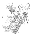
- Fig. 1 is a perspective view showing a connection arrangement between a multi connecting terminal type transmission unit and a control unit according to the embodiment of the invention.
- reference numeral 1 denotes a multi connecting terminal type transmission unit fixed to an attaching plate 31 and 2 indicates a control unit.
- Each of the casing (housings) of the transmission unit 1 and control unit 2 is molded articles made of a synthetic resin.
- Screw terminal portions 3a and 3b each consisting of a plurality of screw terminals are provided for two opposite side portions of the transmission unit 1.
- the screw terminal portions 3a and 3b are used for connection with a serial transmission line 30.
- a transmission side connector portion 4 (first connector) is integrally vertically provided on another side.
- the screw terminal portions 3a and 3b serve as connecting portions to be connected with other transmission units through the transmission lines 30.
- the transmission side connector portion 4 serves as a connecting portion to be connected with the control unit 2.
- the connector portion 4 comprises a housing 7 and a number of terminals 8 arranged in the housing 7.
- the housing 7 has an elongated opening 5 in the top surface and retaining members 6 which are projected upward from both end portions.
- a screw terminal portion 9 consisting of a number of screw terminals is provided on one side in the longitudinal direction of the control unit 2.
- the screw terminal portion 9 serves as a connecting portion to be connected with the apparatuses to be controlled.
- a relay 10 and a circuit module 11 for input/output are detachably attached to the upper surface of the control unit 2.
- An apparatus side connector portion 16 (first connector) is provided on one side portion of the control unit 2 at the position adjacent to the screw terminal portion 9 in a manner similar to the constitution of the transmission side connector portion 4 in the multi connecting terminal type transmission unit 1 mentioned above.
- the connector portion 16 has a housing 14 having an elongated opening 12 in the upper surface and retaining members 13 which are projected upward from both end portions of the housing.
- the connector portion 16 also has a plurality of terminals 15 as many as the number of terminals 8.
- the terminal 15 are arranged in the housing 14.
- the connecting unit 17 comprises a flat cable 19 and connector portions 20a and 20b made of a synthetic resin.
- the flat cable 19 is integrally constituted by arranging a plurality of cables 18 as many as the terminals 8 or 15 so as to be parallel with one another. Lead wires are provided in the sheath portions of the cables 18, respectively.
- the connector portions 20a and 20b (second connectors) are attached to both end portions of the flat cable 19. Retaining concave portions 21a and 21b are formed on both sides of the connector portions 20a and 20b in correspondence to the retaining members 6 and 13 of the connector portions 4 and 16 on the transmission unit and control unit sides, respectively.
- the connector portions 20a and 20b of the connecting unit 17 are inserted into the elongated openings 5 and 12 of the connector portions 4 and 16 of the transmission unit 1 and control unit 2, respectively.
- the terminals 8 and 15 of the transmission unit 1 and control unit 2 are connected through the lead wires of the connecting unit 17, respectively. Since the retaining member 6 and 13 are retained in the retaining concave portions 21a and 21b, the connector portions 20a and 20b are stably held to the connector portions 4 and 16, respectively.
- Fig. 2 is a block diagram of a transmission system using the connection arrangement of the multi connecting terminal type transmission unit 1 and control unit 2 of the invention.
- Reference numeral 22 denotes a transmission unit as a main station and 23 indicates apparatuses to be controlled by the control unit 2.
- the transmission unit 1 and control unit 2 are connected by the connecting unit 17.
- a control signal is sent from the transmission unit 22 to the control unit 2 through the transmission unit 1.
- the apparatuses 23 to be controlled are made operative in response to the control signals and operation signals, detection signals and the like are contrarily sent from the apparatuses 23 to be controlled to the transmission unit 22 through the control unit 2 and the multi connecting terminal type transmission unit 1.
- the transmission units 22 and 1 are mutually connected by the serial transmission line 30.
- the transmission unit 1 converts an input signal transmitted via the transmission line 30 into parallel signals and also decodes into a format of a control signal to be given to the corresponding relay 10 or module 11 in the control unit 2.
- the transmission unit 1 also has a function to directly transmit the input serial signal to the transmission unit 1 at the next stage or to amplify the input serial signal and thereafter transmit to the transmission unit 1 at the nect stage.
- the transmission unit 1 encodes the operation signal, detection signal and the like from the control unit 2 and converts into the serial signal and sends to the transmission unit 22.
- the transmission unit 1 has a CPU, a memory, an input/output interface and the like to execute the foregoing operations.
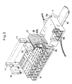
- Fig. 3 shows another embodiment.
- the connector portions 4 and 20a of the connecting unit 17 on the side of the transmission unit 1 are omitted.
- the lead wire of each cable 18 of the flat cable 19 is fixedly connected to the circuit board in the transmission unit 1 by soldering. Therefore, according to this embodiment, on the side of the control unit 2, by connecting the connector portions 16 and 20b, the control unit 2 can be completely connected with the transmission unit 1.
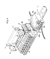
- Fig. 4 shows further another embodiment, in which the connector portions 16 and 20b on the side of the control unit 2 are omitted.
- the end portions of the cables provided with the connector portion 20b are connected to the circuit board of the control unit 2 by soldering. It is sufficient to connect the connector portion 20a with the connector portion 4 on the side of the transmission unit 1.
- the connector portion 20 b is provided for the transmission unit 1 so as to be projected in the side direction.
- the apparatus side connector portion 16 of the control unit 2 is provided so that the connecting surface faces the side direction in correspondence to the connector portion 20b.
- the connector portion 20b is provided on the upper surface of the unit 1 and the connector portion 16 is provided on the lower surface of the control unit 2.
- the connector portion 20b may be also provided on the lower surface of the unit 1 and the connector portion 16 may be also provided on the upper surface of the control unit 2.
- connector portion 4 may be also provided for the transmission unit 1 and the connector portion 20a may be also provided for the control unit 2.
Landscapes
- Engineering & Computer Science (AREA)
- Microelectronics & Electronic Packaging (AREA)
- Selective Calling Equipment (AREA)
- Connections Arranged To Contact A Plurality Of Conductors (AREA)
Applications Claiming Priority (2)
| Application Number | Priority Date | Filing Date | Title |
|---|---|---|---|
| JP2695587A JPS63264884A (ja) | 1986-12-04 | 1987-02-06 | 多点型伝送ユニツトと制御機器との接続構造 |
| JP26955/87 | 1987-02-06 |
Publications (2)
| Publication Number | Publication Date |
|---|---|
| EP0278430A2 true EP0278430A2 (fr) | 1988-08-17 |
| EP0278430A3 EP0278430A3 (fr) | 1989-11-29 |
Family
ID=12207577
Family Applications (1)
| Application Number | Title | Priority Date | Filing Date |
|---|---|---|---|
| EP88101705A Withdrawn EP0278430A3 (fr) | 1987-02-06 | 1988-02-05 | Assemblage de connexion entre un dispositif de commande et un dispositif de transmission de signaux |
Country Status (2)
| Country | Link |
|---|---|
| US (1) | US4878860A (fr) |
| EP (1) | EP0278430A3 (fr) |
Cited By (7)
| Publication number | Priority date | Publication date | Assignee | Title |
|---|---|---|---|---|
| WO1991015037A1 (fr) * | 1990-03-29 | 1991-10-03 | Ab Mecman | Dispositif de liaison electrique pour des soupapes pilotes dans une rangee de soupapes |
| GB2244607B (en) * | 1990-04-28 | 1994-12-21 | Bach & Co | Switching device,in particular relay |
| GB2286731A (en) * | 1991-07-05 | 1995-08-23 | Mod Tap W Corp | Electrical connection system |
| AU679386B2 (en) * | 1991-07-05 | 1997-06-26 | Mod-Tap W Corporation | Electrical connection system |
| CN101718829A (zh) * | 2009-12-30 | 2010-06-02 | 中兴通讯股份有限公司 | 软排线缆的测试插座及测试方法 |
| CN103587639A (zh) * | 2013-09-29 | 2014-02-19 | 苏州小蜻蜓电动车有限公司 | 一种电动车控制器 |
| CN114465094A (zh) * | 2022-01-27 | 2022-05-10 | 淮南安能电子有限公司 | 一种金属铠装移开式柜用核心控制单元 |
Families Citing this family (11)
| Publication number | Priority date | Publication date | Assignee | Title |
|---|---|---|---|---|
| US5000692A (en) * | 1988-09-14 | 1991-03-19 | Matsushita Electric Works, Ltd. | I/O relay interface module |
| US5037310A (en) * | 1989-12-06 | 1991-08-06 | Gespac, Inc. | Connector apparatus and method for distributed control modules used in computer networks |
| US5083743A (en) * | 1991-04-25 | 1992-01-28 | Whitman Medical Corporation | Slip thread adjustable in-line valve for sterile fluids |
| EP0762581B1 (fr) * | 1995-09-04 | 1999-04-07 | Rockwell Automation AG | Dispositif pour fixer un appareil électrique sur un adaptateur |
| US5897399A (en) * | 1997-01-16 | 1999-04-27 | Hewlett-Packard Company | Versatile input/output control and power distribution block for use with automated tooling |
| US6537109B1 (en) | 1997-01-16 | 2003-03-25 | Hewlett-Packard Company | Chainable I/O termination block system |
| US6570146B1 (en) | 1998-12-23 | 2003-05-27 | Hewlett-Packard Company | Submersible sensor output inverter |
| US6416356B1 (en) | 2000-06-02 | 2002-07-09 | Astec International Limited | AC interface for electrical equipment racks |
| CN102835197B (zh) * | 2010-03-31 | 2015-12-09 | 威德米勒界面有限公司及两合公司 | 能用作总线的连接模块 |
| TW201318284A (zh) * | 2011-10-21 | 2013-05-01 | Acer Inc | 用於電腦系統之公連接座及母連接座 |
| DE102012213281B4 (de) * | 2012-07-27 | 2024-06-06 | Phoenix Contact Gmbh & Co. Kg | Feldbusbaukastensystem, Trägermodul und Feldbusmodul |
Family Cites Families (7)
| Publication number | Priority date | Publication date | Assignee | Title |
|---|---|---|---|---|
| IT1108241B (it) * | 1978-05-29 | 1985-12-02 | Finike Italiana Marposs | Apaprecchiatura elettronica modulare per controlli multipli simultanei |
| US4477862A (en) * | 1982-05-19 | 1984-10-16 | Gould Inc. | Backplane connector |
| US4558914A (en) * | 1982-09-23 | 1985-12-17 | Gould Inc. | Readily expandable input/output construction for programmable controller |
| US4709975A (en) * | 1983-09-16 | 1987-12-01 | Williams Ii Joseph R | Releasable snap connector |
| JPS6075903A (ja) * | 1983-09-30 | 1985-04-30 | Matsushita Electric Works Ltd | シ−ケンス制御装置 |
| US4581495A (en) * | 1984-05-02 | 1986-04-08 | Buscom Systems Inc. | Modular telephone housing |
| DE3603750C3 (de) * | 1986-02-06 | 1996-10-17 | Siemens Ag | Automatisierungsgerät |
-
1988
- 1988-02-05 US US07/153,295 patent/US4878860A/en not_active Expired - Lifetime
- 1988-02-05 EP EP88101705A patent/EP0278430A3/fr not_active Withdrawn
Cited By (11)
| Publication number | Priority date | Publication date | Assignee | Title |
|---|---|---|---|---|
| WO1991015037A1 (fr) * | 1990-03-29 | 1991-10-03 | Ab Mecman | Dispositif de liaison electrique pour des soupapes pilotes dans une rangee de soupapes |
| US5277622A (en) * | 1990-03-29 | 1994-01-11 | Ab Rexroth Mecman | Electric connecting device for pilot valves in a valve array |
| GB2244607B (en) * | 1990-04-28 | 1994-12-21 | Bach & Co | Switching device,in particular relay |
| GB2286731A (en) * | 1991-07-05 | 1995-08-23 | Mod Tap W Corp | Electrical connection system |
| GB2286731B (en) * | 1991-07-05 | 1995-11-29 | Mod Tap W Corp | Electrical connection system |
| AU679386B2 (en) * | 1991-07-05 | 1997-06-26 | Mod-Tap W Corporation | Electrical connection system |
| EP0685905A3 (fr) * | 1991-07-05 | 1997-11-19 | Mod-Tap W. Corp. | Système de connecteur électrique |
| CN101718829A (zh) * | 2009-12-30 | 2010-06-02 | 中兴通讯股份有限公司 | 软排线缆的测试插座及测试方法 |
| CN101718829B (zh) * | 2009-12-30 | 2013-08-07 | 中兴通讯股份有限公司 | 软排线缆的测试插座及测试方法 |
| CN103587639A (zh) * | 2013-09-29 | 2014-02-19 | 苏州小蜻蜓电动车有限公司 | 一种电动车控制器 |
| CN114465094A (zh) * | 2022-01-27 | 2022-05-10 | 淮南安能电子有限公司 | 一种金属铠装移开式柜用核心控制单元 |
Also Published As
| Publication number | Publication date |
|---|---|
| US4878860A (en) | 1989-11-07 |
| EP0278430A3 (fr) | 1989-11-29 |
Similar Documents
| Publication | Publication Date | Title |
|---|---|---|
| US4878860A (en) | Connection arrangement between control device and signal transmission device | |
| US4639054A (en) | Cable terminal connector | |
| US5091826A (en) | Printed wiring board connector | |
| RU2251147C2 (ru) | Система для контроля конфигурации соединения портов данных | |
| US4490775A (en) | Universal programmable interface | |
| US4634209A (en) | Modular plug connector | |
| US5293013A (en) | Switching cable | |
| US6717486B2 (en) | Multi-circuit signal transformer | |
| GB2269275A (en) | Micropin connector system | |
| US6146153A (en) | Adapter apparatus and method for transmitting electronic data | |
| ATE59519T1 (de) | Verteilereinrichtung, insbesondere fuer den hauptverteiler von fernsprechanlagen. | |
| DK170937B1 (da) | Forbindelsesstykke til kabel | |
| EP0326971A2 (fr) | Structure assemblée pour un dispositif électronique | |
| US6640270B1 (en) | Terminal connection box and plug | |
| US4542372A (en) | Data distribution apparatus | |
| US5290180A (en) | Serial line connector | |
| IE913864A1 (en) | Electrical connector | |
| GB2035716A (en) | Improvements relating to electrical signal connectors | |
| JPS58201277A (ja) | デ−タステ−シヨンにおけるインタ−フエ−ス用内部接続機構 | |
| US6257936B1 (en) | Set of devices for transferring electric signals | |
| GB2044949A (en) | A terminating connector for a fibre optic able | |
| US5140172A (en) | Interface module for a bus interface | |
| JP3387116B2 (ja) | 電子機器 | |
| KR900003183B1 (ko) | 플래트 케이블(flat cable)을 통한 성형접속장치 | |
| EP1135923B3 (fr) | Systeme de distribution et de transfert de signaux multimedia et de communication |
Legal Events
| Date | Code | Title | Description |
|---|---|---|---|
| PUAI | Public reference made under article 153(3) epc to a published international application that has entered the european phase |
Free format text: ORIGINAL CODE: 0009012 |
|
| 17P | Request for examination filed |
Effective date: 19880205 |
|
| AK | Designated contracting states |
Kind code of ref document: A2 Designated state(s): AT BE CH DE ES FR GB GR IT LI LU NL SE |
|
| PUAL | Search report despatched |
Free format text: ORIGINAL CODE: 0009013 |
|
| AK | Designated contracting states |
Kind code of ref document: A3 Designated state(s): AT BE CH DE ES FR GB GR IT LI LU NL SE |
|
| 17Q | First examination report despatched |
Effective date: 19920407 |
|
| STAA | Information on the status of an ep patent application or granted ep patent |
Free format text: STATUS: THE APPLICATION IS DEEMED TO BE WITHDRAWN |
|
| 18D | Application deemed to be withdrawn |
Effective date: 19930406 |