EP0278468B1 - Dispositif pour éclairage à lampes fluorescentes - Google Patents
Dispositif pour éclairage à lampes fluorescentes Download PDFInfo
- Publication number
- EP0278468B1 EP0278468B1 EP88101840A EP88101840A EP0278468B1 EP 0278468 B1 EP0278468 B1 EP 0278468B1 EP 88101840 A EP88101840 A EP 88101840A EP 88101840 A EP88101840 A EP 88101840A EP 0278468 B1 EP0278468 B1 EP 0278468B1
- Authority
- EP
- European Patent Office
- Prior art keywords
- fluorescent lamps
- transformer
- driving circuit
- filaments
- contacts
- Prior art date
- Legal status (The legal status is an assumption and is not a legal conclusion. Google has not performed a legal analysis and makes no representation as to the accuracy of the status listed.)
- Expired - Lifetime
Links
- 238000004804 winding Methods 0.000 claims description 10
- 239000003990 capacitor Substances 0.000 claims description 4
- 239000003086 colorant Substances 0.000 description 3
- 238000010276 construction Methods 0.000 description 2
- 238000012986 modification Methods 0.000 description 2
- 230000004048 modification Effects 0.000 description 2
- 108010043121 Green Fluorescent Proteins Proteins 0.000 description 1
- 230000003287 optical effect Effects 0.000 description 1
Images


Classifications
-
- H—ELECTRICITY
- H05—ELECTRIC TECHNIQUES NOT OTHERWISE PROVIDED FOR
- H05B—ELECTRIC HEATING; ELECTRIC LIGHT SOURCES NOT OTHERWISE PROVIDED FOR; CIRCUIT ARRANGEMENTS FOR ELECTRIC LIGHT SOURCES, IN GENERAL
- H05B47/00—Circuit arrangements for operating light sources in general, i.e. where the type of light source is not relevant
- H05B47/10—Controlling the light source
- H05B47/155—Coordinated control of two or more light sources
-
- Y—GENERAL TAGGING OF NEW TECHNOLOGICAL DEVELOPMENTS; GENERAL TAGGING OF CROSS-SECTIONAL TECHNOLOGIES SPANNING OVER SEVERAL SECTIONS OF THE IPC; TECHNICAL SUBJECTS COVERED BY FORMER USPC CROSS-REFERENCE ART COLLECTIONS [XRACs] AND DIGESTS
- Y10—TECHNICAL SUBJECTS COVERED BY FORMER USPC
- Y10S—TECHNICAL SUBJECTS COVERED BY FORMER USPC CROSS-REFERENCE ART COLLECTIONS [XRACs] AND DIGESTS
- Y10S315/00—Electric lamp and discharge devices: systems
- Y10S315/05—Starting and operating circuit for fluorescent lamp
-
- Y—GENERAL TAGGING OF NEW TECHNOLOGICAL DEVELOPMENTS; GENERAL TAGGING OF CROSS-SECTIONAL TECHNOLOGIES SPANNING OVER SEVERAL SECTIONS OF THE IPC; TECHNICAL SUBJECTS COVERED BY FORMER USPC CROSS-REFERENCE ART COLLECTIONS [XRACs] AND DIGESTS
- Y10—TECHNICAL SUBJECTS COVERED BY FORMER USPC
- Y10S—TECHNICAL SUBJECTS COVERED BY FORMER USPC CROSS-REFERENCE ART COLLECTIONS [XRACs] AND DIGESTS
- Y10S315/00—Electric lamp and discharge devices: systems
- Y10S315/07—Starting and control circuits for gas discharge lamp using transistors
Definitions
- the present invention relates to a system for sequentially lighting fluorescent lamps.
- This system can be preferably employed in a color printer, a color scanner or the like.
- tricolor light sources are applied to an original document to be read, sequentially first in red, second in green and third in blue.
- the original document is relatively moved with respect to the light sources for the scanning thereof so that reflected light from the light sources may be read out by an image pickup means such as a CCD (charge coupled device) or the like.
- an image pickup means such as a CCD (charge coupled device) or the like.
- a plurality of fluorescent lamps each for independently emitting light in one of the aforementioned three colors are generally employed as the light sources.
- Fig. 1 illustrates an electric circuit of one of the conventional lighting systems.
- Red, green and blue fluorescent lamps 1, 2 and 3 respectively are connected at their respective filaments R0, G0 and B0 commonly to the first winding 4a of a power transformer 4.
- the other filaments R1, G1 and B1 of the fluorescent lamps 1, 2 and 3 are independently connected to the second winding 4b, to the third one 4c and to the fourth one 4d of the transformer 4, respectively.
- the primary winding 4p of the transformer 4 is connected to a driving circuit 5 through a line l1 so as to be electrically biased through the driving circuit 5.
- the line l1 is also connected to three starting circuits 9, 10 and 11 through contacts S1, S1 and S3 of switching circuits 6, 7 and 8, respectively so as to be electrically biased by the starting circuits 9, 10 and 11.
- the switching circuits 6, 7 and 8 sequentially connect the line l1 to the starting circuits 9, 10 and 11, and cut the former off the latter by virtue of the driving circuit 5 through a line l2 every predetermined time.
- the switching circuits 6, 7 and 8 each comprise, for example, relays and the like.
- a power switch S0 is initially turned on.
- the transformer 4 is charged with electric current therethrough.
- filament voltage V0 common to all the fluorescent lamps 1 to 3 is applied to the filaments R0, G0 and B0 thereof, whereas filament voltage V1, V2 and V3 are independently applied to the other filaments R1, G1 and B1 of the fluorescent lamps 1 to 3, respectively.
- the filaments of the red, green and blue fluorescent lamps 1, 2 and 3 respectively are heated and kept on being heated in use.
- the driving circuit 5 drives the switching circuits 6, 7 and 8 so that the first, second and third contacts S1, S2 and S3 may be sequentially connected or disconnected every predetermined time.
- the first, second and third starting circuits 9, 10 and 11 are sequentially connected to the line l1 so that the first, second and third starting voltage V4, V5 and V6 are sequentially independently applied between both the filaments R0-R1 of the red fluorescent lamp 1, between those G0-G1 of the green fluorescent lamp 2 and between those B0-B1 of the blue fluorescent lamp 3 through current-limiting capacitors C1, C2 and C3, respectively. Consequently, the corresponding fluorescent lamps 1 to 3 are selectively turned on and off so that the scanning and readout of the original document may be conducted with the use of three different colors.
- the present invention has been developed with a view to substantially eliminating the above described disadvantage inherent in the prior art system for lighting fluorescent lamps, and has for its essential object to provide an improved system for lighting the fluorescent lamps which enables small-sized apparatus at reduced production cost.
- This problem is solved by a system with the features of Claim 1.
- Another important aspect of the present invention is to provide a system of the above described type which is simple in construction and stable in functioning.
- Fig. 2 illustrates an electric circuit of a system for lighting fluorescent lamps according to one preferred embodiment of the present invention.
- a plurality of fluorescent lamps i.e., red, green and blue fluorescent lamps 21, 22 and 23 respectively are provided as light sources.
- Filaments R10, G10 and B10 of the fluorescent lamps 21, 22 and 23 are commonly connected to the first winding 24a of a transformer 24 which generates filament voltage and starting voltage of the fluorescent lamps 21, 22 and 23.
- the other filaments R11, G11 and B11 of the fluorescent lamps 21, 22 and 23 are independently connected to the second, third and fourth winding 24b, 24c and 24d of the transformer 24, respectively.
- the primary winding 24p of the transformer 24 is connected to a driving circuit 25 through a line l11 so as to be electrically biased by an output therefrom.
- the driving circuit 25 is also connected to a line l12 which is further connected to a switching circuit 26 comprising, for example, relays.
- the driving circuit 25 is further connected to a power switch S20 so as to be supplied with electric current through it and a line l10.
- the switching circuit 26 has a plurality of contacts S11, S12 and S13 for sequentially controlling electric connection and cut-off at desired timing described later by virtue of the driving circuit 25.
- high-voltage winding 24e required for starting the fluorescent lamps.
- One terminal of the high-voltage winding 24e is connected to one common terminal of the filaments R10, G10 and B10 of the fluorescent lamps 21, 22 and 23, respectively, whereas the other terminal thereof is connected to one common terminal of the contacts S11, S12 and S13 of the switching circuit 26 through a current-limiting capacitor C11.
- the other terminal of each contact S11, S12 or S13 is independently connected to one terminal of each filament R11, G11 or B11, respectively.
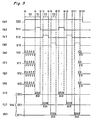
- Fig. 3 is a time-chart showing the operation of the system of the present invention.
- the power switch S20 is initially turned on at the time t0 in Fig. 3(a) so that the driving circuit 25 may be electrically biased.
- the transformer 24 is then electrically biased through the driving circuit 25.
- the filament voltage V10 is applied commonly to the filaments R10, G10 and B10 of the fluorescent lamps 21, 22 and 23, respectively.
- the filament voltage V11, V12 and V13 are independently applied to the other filaments R11, G11 and B11 of the fluorescent lamps 21, 22 and 23, respectively. In this way, the filaments of the red, green and blue fluorescent lamps 21, 22 and 23 are heated.
- the filament voltage V10 to V13 are each, for example, 8V. Each filament is continuously heated as far as the time t13 during the use of the fluorescent lamps.
- the switching circuit 26 Upon lapse of a period T0 from the time t0 to t1 required for preheating the filaments, the switching circuit 26 is electrically biased by the driving circuit 25.
- the first, second and third contacts S11, S12 and S13 are sequentially charged with electric current for predetermined periods T1 from the time t1 to t2, T2 from the time from t3 to t4 and T3 from the time t5 to t6, respectively. Accordingly, as shown in Figs.
- the starting voltage V14 is sequentially independently applied, through the current-limiting capacitor C11, between the filaments R10 and R11, between those G10 and G11 and between those B10 and B11 of the red, green and blue fluorescent lamps 21, 22 and 23, respectively.
- the starting voltage V14 is, for example, 300V, thereby to sequentially light the fluorescent lamps 21 to 23 at the aforementioned predetermined time.
- the fluorescent lamps 21 to 23 are applied to the paper sheet (not shown) so that the scanning and readout thereof may be conducted with the use of three colors.
- the operation after the time t7 up to the completion time t13 is the same as above.
Landscapes
- Facsimile Scanning Arrangements (AREA)
- Circuit Arrangements For Discharge Lamps (AREA)
- Discharge-Lamp Control Circuits And Pulse- Feed Circuits (AREA)
- Light Sources And Details Of Projection-Printing Devices (AREA)
Claims (3)
- Dispositif pour éclairage à lampes fluorescentes, comprenant:
une pluralité de lampes fluorescentes (21, 22, 23);
un transformateur (24) générant une tension de filament (V10, V11, V12, V13) des lampes fluorescentes (21, 22, 23);
un circuit d'attaque (25) pour polariser électriquement le transformateur (24);
une pluralité de contacts (S11, S12, S13) étant actionnés de manière séquentielle par le circuit d'attaque (25) pour connecter et déconnecter les lampes (21, 22, 23) à une tension d'allumage (V14), une seule lampe (21, 22, 23) étant connectée à la fois
caractérisé en ce que
la tension d'allumage (V14) est générée par un simple enroulement secondaire (24e) du même transformateur (24) que celui génèrant la tension de filament (V10-V13), et
les contacts (S11, S12, S13) sont placés dans un seul circuit de commutation (26). - Dispositif selon la revendication 1, caractérisé en ce que l'enroulement (24e) est connecté à une borne commune des contacts (S11, S12, S13) du circuit de commutation (26) par l'intermédiaire d'un seul condensateur limiteur de courant (C11).
- Dispositif selon la revendication 1 ou 2, caractérisé en ce que les lampes fluorescentes (21, 22, 23) émettent une lumière dans le rouge, le vert et le bleu, respectivement.
Applications Claiming Priority (2)
| Application Number | Priority Date | Filing Date | Title |
|---|---|---|---|
| JP29331/87 | 1987-02-10 | ||
| JP62029331A JPS63198294A (ja) | 1987-02-10 | 1987-02-10 | 蛍光灯の点灯方式 |
Publications (3)
| Publication Number | Publication Date |
|---|---|
| EP0278468A2 EP0278468A2 (fr) | 1988-08-17 |
| EP0278468A3 EP0278468A3 (fr) | 1991-01-09 |
| EP0278468B1 true EP0278468B1 (fr) | 1994-07-20 |
Family
ID=12273245
Family Applications (1)
| Application Number | Title | Priority Date | Filing Date |
|---|---|---|---|
| EP88101840A Expired - Lifetime EP0278468B1 (fr) | 1987-02-10 | 1988-02-09 | Dispositif pour éclairage à lampes fluorescentes |
Country Status (5)
| Country | Link |
|---|---|
| US (1) | US4947086A (fr) |
| EP (1) | EP0278468B1 (fr) |
| JP (1) | JPS63198294A (fr) |
| CA (1) | CA1324185C (fr) |
| DE (1) | DE3850682T2 (fr) |
Families Citing this family (5)
| Publication number | Priority date | Publication date | Assignee | Title |
|---|---|---|---|---|
| DE3938676C1 (fr) * | 1989-11-22 | 1991-06-06 | Trilux-Lenze Gmbh + Co Kg, 5760 Arnsberg, De | |
| US5243258A (en) * | 1991-08-30 | 1993-09-07 | North American Philips Corporation | Fluorescent lamp electrode disconnect arrangement |
| US5552673A (en) * | 1994-10-04 | 1996-09-03 | Kenwood; Michael | Theft resistant compact fluorescent lighting system |
| US7586268B2 (en) * | 2005-12-09 | 2009-09-08 | Lutron Electronics Co., Inc. | Apparatus and method for controlling the filament voltage in an electronic dimming ballast |
| JP4808168B2 (ja) * | 2007-02-23 | 2011-11-02 | シャープ株式会社 | 表示装置 |
Family Cites Families (13)
| Publication number | Priority date | Publication date | Assignee | Title |
|---|---|---|---|---|
| US2487714A (en) * | 1947-06-23 | 1949-11-08 | Mega Corp | Progressive illuminating means |
| DE1497880B2 (de) * | 1966-07-22 | 1971-11-25 | Patent-Treuhand-Gesellschaft für elektrische Glühlampen mbH, 8000 München | Farbmischanlage |
| US3638070A (en) * | 1969-10-17 | 1972-01-25 | Richard W Powell | Fluorescent lamp starting and control circuit |
| US4075476A (en) * | 1976-12-20 | 1978-02-21 | Gte Sylvania Incorporated | Sinusoidal wave oscillator ballast circuit |
| US4082981A (en) * | 1977-02-28 | 1978-04-04 | Westinghouse Electric Corporation | Energy saving device for a standard fluorescent lamp system |
| JPS5694372A (en) * | 1979-12-27 | 1981-07-30 | Canon Inc | Exposure control device |
| US4339690A (en) * | 1980-08-01 | 1982-07-13 | Gte Laboratories Incorporated | Energy saving fluorescent lighting system |
| US4413209A (en) * | 1981-10-05 | 1983-11-01 | Gte Products Corporation | Series-connected discharge device ballast apparatus |
| JPS58100843A (ja) * | 1981-12-11 | 1983-06-15 | Minolta Camera Co Ltd | 露光用光源装置 |
| US4526463A (en) * | 1982-07-30 | 1985-07-02 | CH2 M Hill, Inc. | Apparatus for exposing photosensitive media |
| JPS60163397A (ja) * | 1984-02-03 | 1985-08-26 | シャープ株式会社 | 螢光灯点灯装置 |
| FR2559334B1 (fr) * | 1984-02-03 | 1988-02-26 | Ssih Equipment Sa | Dispositif d'alimentation pour commander l'intensite lumineuse d'au moins une lampe a decharge et utilisation dudit dispositif |
| US4661745A (en) * | 1984-02-06 | 1987-04-28 | Gte Products Corporation | Rapid-start fluorescent lamp power reducer |
-
1987
- 1987-02-10 JP JP62029331A patent/JPS63198294A/ja active Pending
-
1988
- 1988-02-09 EP EP88101840A patent/EP0278468B1/fr not_active Expired - Lifetime
- 1988-02-09 DE DE3850682T patent/DE3850682T2/de not_active Expired - Fee Related
- 1988-02-09 CA CA000558530A patent/CA1324185C/fr not_active Expired - Fee Related
- 1988-02-10 US US07/154,328 patent/US4947086A/en not_active Expired - Lifetime
Also Published As
| Publication number | Publication date |
|---|---|
| US4947086A (en) | 1990-08-07 |
| DE3850682T2 (de) | 1994-10-27 |
| EP0278468A3 (fr) | 1991-01-09 |
| DE3850682D1 (de) | 1994-08-25 |
| EP0278468A2 (fr) | 1988-08-17 |
| CA1324185C (fr) | 1993-11-09 |
| JPS63198294A (ja) | 1988-08-16 |
Similar Documents
| Publication | Publication Date | Title |
|---|---|---|
| KR100497578B1 (ko) | 영상 표시 기기용의 대기 전원 공급 장치 | |
| US5027033A (en) | High-efficiency fluorescent lamp operating circuit | |
| JP2651764B2 (ja) | ガス放電ランプの明るさを制御する電子切換装置 | |
| EP0278468A2 (fr) | Dispositif pour éclairage à lampes fluorescentes | |
| JPH034491A (ja) | スイッチング回路装置 | |
| KR0179870B1 (ko) | 모터 구동 제어 회로 | |
| US3979599A (en) | Operatively interlocked electronic system | |
| US7477020B2 (en) | Electronic ballast having a reduced reverse voltage at the start | |
| EP0491434B1 (fr) | Dispositif pour déconnexion d'une électrode d'une lampe | |
| KR0172864B1 (ko) | 전자레인지의 마그네트론 구동회로 | |
| TW234807B (fr) | ||
| RU2012159C1 (ru) | Способ формирования видеосигнала цветных изображений и устройство для его осуществления | |
| WO1996013141A3 (fr) | Montage de circuit pour lampe comprenant un premier et un second branchement de circuit relies a celle-ci | |
| JPS58218799A (ja) | 放電灯用インバ−タにおける全光−調光切換装置 | |
| EP0784912B1 (fr) | Dispositif de circuit | |
| JP3513583B2 (ja) | バックライト用放電灯点灯装置 | |
| US5243258A (en) | Fluorescent lamp electrode disconnect arrangement | |
| EP1496594B1 (fr) | Alimentation de puissance electronique d'éclairage de secours avec lampe fluorescente | |
| US3573629A (en) | Transformer power supply for remote controlled receivers with provision for fast warm-up | |
| JPH02256199A (ja) | 放電灯点灯装置 | |
| JPH09219291A (ja) | 蛍光灯点灯回路 | |
| JPH03119697A (ja) | 放電灯点灯装置 | |
| JPH1022081A (ja) | 放電灯点灯装置 | |
| JPH01163998A (ja) | 放電灯の点灯回路 | |
| JPH11206128A (ja) | 信号伝達方法および装置 |
Legal Events
| Date | Code | Title | Description |
|---|---|---|---|
| PUAI | Public reference made under article 153(3) epc to a published international application that has entered the european phase |
Free format text: ORIGINAL CODE: 0009012 |
|
| 17P | Request for examination filed |
Effective date: 19880209 |
|
| AK | Designated contracting states |
Kind code of ref document: A2 Designated state(s): DE GB |
|
| PUAL | Search report despatched |
Free format text: ORIGINAL CODE: 0009013 |
|
| AK | Designated contracting states |
Kind code of ref document: A3 Designated state(s): DE GB |
|
| 17Q | First examination report despatched |
Effective date: 19930120 |
|
| GRAA | (expected) grant |
Free format text: ORIGINAL CODE: 0009210 |
|
| AK | Designated contracting states |
Kind code of ref document: B1 Designated state(s): DE GB |
|
| REF | Corresponds to: |
Ref document number: 3850682 Country of ref document: DE Date of ref document: 19940825 |
|
| PLBE | No opposition filed within time limit |
Free format text: ORIGINAL CODE: 0009261 |
|
| STAA | Information on the status of an ep patent application or granted ep patent |
Free format text: STATUS: NO OPPOSITION FILED WITHIN TIME LIMIT |
|
| 26N | No opposition filed | ||
| REG | Reference to a national code |
Ref country code: GB Ref legal event code: IF02 |
|
| PGFP | Annual fee paid to national office [announced via postgrant information from national office to epo] |
Ref country code: DE Payment date: 20050203 Year of fee payment: 18 |
|
| PGFP | Annual fee paid to national office [announced via postgrant information from national office to epo] |
Ref country code: GB Payment date: 20050209 Year of fee payment: 18 |
|
| PG25 | Lapsed in a contracting state [announced via postgrant information from national office to epo] |
Ref country code: GB Free format text: LAPSE BECAUSE OF NON-PAYMENT OF DUE FEES Effective date: 20060209 |
|
| PG25 | Lapsed in a contracting state [announced via postgrant information from national office to epo] |
Ref country code: DE Free format text: LAPSE BECAUSE OF NON-PAYMENT OF DUE FEES Effective date: 20060901 |
|
| GBPC | Gb: european patent ceased through non-payment of renewal fee |
Effective date: 20060209 |