EP0278683B1 - Automatische Vorrichtung zum Reinigen eines Extrusionsplastometers für thermoplastische Materialien - Google Patents
Automatische Vorrichtung zum Reinigen eines Extrusionsplastometers für thermoplastische Materialien Download PDFInfo
- Publication number
- EP0278683B1 EP0278683B1 EP88300950A EP88300950A EP0278683B1 EP 0278683 B1 EP0278683 B1 EP 0278683B1 EP 88300950 A EP88300950 A EP 88300950A EP 88300950 A EP88300950 A EP 88300950A EP 0278683 B1 EP0278683 B1 EP 0278683B1
- Authority
- EP
- European Patent Office
- Prior art keywords
- cylinder
- die
- cleaning
- cleaning rod
- pad
- Prior art date
- Legal status (The legal status is an assumption and is not a legal conclusion. Google has not performed a legal analysis and makes no representation as to the accuracy of the status listed.)
- Expired
Links
Images





Classifications
-
- G—PHYSICS
- G01—MEASURING; TESTING
- G01N—INVESTIGATING OR ANALYSING MATERIALS BY DETERMINING THEIR CHEMICAL OR PHYSICAL PROPERTIES
- G01N11/00—Investigating flow properties of materials, e.g. viscosity, plasticity; Analysing materials by determining flow properties
- G01N11/02—Investigating flow properties of materials, e.g. viscosity, plasticity; Analysing materials by determining flow properties by measuring flow of the material
- G01N11/04—Investigating flow properties of materials, e.g. viscosity, plasticity; Analysing materials by determining flow properties by measuring flow of the material through a restricted passage, e.g. tube, aperture
Definitions
- thermoplastics extrusion plastometer cleaning device especially, a device for cleaning automatically the cylinder, piston and die of the extrusion plastometer for testing the plasticity of the thermoplastics.
- Extrusion plastometers test the plasticity of thermoplastics. The test is carried out by extruding melted thermoplastics through a die of a stimulated length and bore at a stipulated temperature and under stipulated pressure to measure the extrusion speed. There are two procedures for the test; Procedure A and Procedure B (stipulated by JIS). In Procedure A, a mass which is extruded in a unit hour is manually cut off to be measured. In Procecure B, a time in which a unit of mass is extruded is measured. The plasticity of the melted polymer materials, such as thermoplastics, is related with the shearing speed thereof. The result of the plasticity test provides one index for their forming. Thus the plasticity test is important. This invention is usable in cleaning the cylinders, pistons and dies used in both of the above described Procedures A and B.
- the prior art manually operated test device has an electric furnace and a stipulated quantity of a test specimen is placed in a metal cylinder which has been controlled to have a measurement temperature by the electric furnace and melted.
- a weight of a stipulated mass is mounted on a piston inserted into the cylinder to extrude the melted specimen downward through a die of small bore arranged in the bottom part of the cylinder.
- Procedure A or B a manual force is applied to the weight to force the specimen residue in the cylinder down out of the cylinder through a die.
- the part of the specimen for a last test sticking to the cylinder, piston and die has to be perfectly removed therefrom. Otherwise correct measurement cannot be made.
- the cylinder has been cleaned by sliding a cylinder cleaning rod with soft cloth wound thereon. The cleaning was carried out by sliding the cylinder cleaning rod manually twice to three times in the cylinder.
- the piston cleaning has been carried out by wiping off the residual specimen on the piston surface with a soft cloth by an examiner.
- the die cleaning was carried out with a brass or wooden rod by taking out the die from the bottom of the cylinder after the cylinder cleaning.
- the cleaning described above must be carried out essentially before a test. Without the cleaning, undesirably the specimen residue of a last test affects a next test.
- the cleaning has to be carried out at high temperatures since the cylinder is heated up to a high temperature as high as 125 to 300° C, which varies depending on specimens. Otherwise the specimen residue is cured, and it becomes difficult to remove it.
- the object of this invention is to provide a cleaning device for use in a in a thermoplastics extrusion plastometer which enables cleaning to be automated, whereby safety is improved, labor is saved, and the precision of measurement is improved.
- DE-A-2140619 discloses a cleaning device for use in a thermoplastics extrusion plastometer in which thermoplastics is fad into a vertically disposed cylinder to be heat melted, and the melted thermoplastics is extruded through a die formed at the bottom of the cylinder by a piston disposed at a plasticity testing position so that the plasticity of the thermoplastics is tested, the cleaning device comprising a piston cleaning unit for cleaning the surface of the piston removed from the cylinder at a plasticity testing position; and a cylinder cleaning unit for cleaning the interior surface of the cylinder.
- a cleaning device for use in a thermoplastics extrusion plastometer in which thermoplastics is fed into a vertically disposed cylinder to be heat melted, and the melted thermoplastics is extruded through a die formed at the bottom of the cylinder by a piston disposed at a plasticity testing position so that the plasticity of the thermoplastics is tested, said device comprising: a piston cleaning unit for cleaning the surface of said piston removed from said cylinder at said plasticity testing position; and a cylinder cleaning unit for cleaning the interior surface of said cylinder characterised in that said cleaning device further comprises a die cleaning unit for cleaning the interior surface of said die without removing said die from said cylinder, a conveying unit for moving said cylinder away from said plasticity testing position to a cylinder cleaning position and a die cleaning position; and control means for automatically sequentially moving said cylinder between said plasticity testing, cylinder cleaning and die cleaning positions.
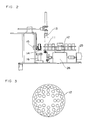
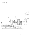
- Fig. 1 is a front view of the general structure of the full automatic extrusion plastometer using the automatic cleaning device according to one embodiment of this invention
- Fig. 2 is a side elevational view of the specimen bottle taking-out mechanism of the charging unit
- Fig. 3 is a plan view of the specimen table
- Fig. 4 is a side elevational view of the mechanism of the specimen charging unit for feeding the specimen taken out from the specimen table to the cylinder
- Fig. 5 is a side elevational view of the general structure, partly in cross section, of the cylinder cleaning unit
- Figs. 6A, 6B and 6C are perspective views explaining the structure and function of the cylinder cleaning rod
- Fig. 6A, 6B and 6C are perspective views explaining the structure and function of the cylinder cleaning rod
- Fig. 6A, 6B and 6C are perspective views explaining the structure and function of the cylinder cleaning rod
- Fig. 6A, 6B and 6C are perspective views explaining the structure and function of the cylinder cleaning rod
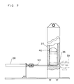
- Fig. 7 is a side elevational view, partly in cross section, of a pad stocker and its surroundings;
- Fig. 8 is a die elevational view, partly in cross section, of a pad holder and its surroundings;
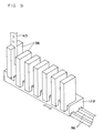
- Fig. 9 is a perspective view of a main portion of a modification of the pad stocker;
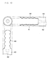
- Fig. 10 is a view showing the structure of the forward end of the cylinder cleaning rod of the modification;
- Fig. 11 is a front view of the general structure, partly in cross section, of the piston cleaning unit;
- Fig 12 is a side elevational view, partly in cross section, of the piston cleaning unit of Fig. 11;
- Fig. 13 is a front view of the geneva in Fig. 12;
- Fig. 14 is a side elevational view of the general structure, partly in cross section, of the die cleaning unit; and
- Fig. 15 is a side elevational view of a major portion of die cleaning unit according to the second embodiment.
- the plastometer comprises an electric furnace, a conveying unit, a test specimen charging unit, a piston unit, a piston cleaning unit, a cylinder cleaning unit, and a die cleaning unit.
- the electric furnace 1 incorporates a cylinder, a die, a heater, etc.
- the conveying unit contains a slide rail 8 arranged horizontally, a stepping motor 9 for moving the electric furnace, etc.
- the test specimen charging unit contains a guide pipe 20, a specimen extruding rod arranged vertically, etc.
- the piston unit contains a piston 27 driven up and down, a weight 32, etc.
- the piston cleaning unit contains bobbins 65 and 74, a piston cleaning mechanism 81, etc.
- the cylinder cleaning unit contains a pad 36, a cylinder cleaning mechanism 52 for driving the pad 36 vertically, etc.
- the die cleaning unit contains a die cleaning rod holder 95, a guide pipe 104, etc.
- the electric furnace 1 is attached vertical to the slide rail 8 for moving the electric furnace 1.
- the stepping motor 9 and the timing belt 10 correctly moves the electric furnace 1 sequentially to a specimen charging position, a plasticity testing position (measuring position), a cylinder cleaning position and a die cleaning position.
- the piston cleaning unit is disposed on a different slide rail perpendicular to the side rail 8.
- Fig. 2 shows a specimen bottle taking out mechanism for taking a specimen bottle 11 from a specimen table 12.
- Fig. 3 shows the specimen table 12 in Fig. 2.
- Fig. 4 shows a specimen charging mechanism for supplying to the cylinder in the electric furnace 1 the specimen in a specimen bottle 11 taken out by the mechanism of Fig. 2.
- the specimen is charged in the following manner.
- the specimen is beforehand scaled in a stipulated amount, and the stipulated amount is put in a bottle 11.
- a required number of the bottles 11 for a test are arranged on the specimen table 12.
- the extrusion plastometer using the automatic cleaning device of this invention will be actuated.
- a specimen taking out robot 13 is actuated to take out one of the specimen bottles 11 from the specimen table 12 to convey the bottle 11 to the specimen holder 14.
- the specimen bottle 11 held by the specimen holder 14 is turned by 180° together with a rotary actuator 15, and the specimen in the bottle 11 is shifted into a linear vibrating feeder 16.
- the linear vibrating feeder 16 begins to feed the specimen.
- the specimen is fed into the cylinder 3 in the electric furnace 1 through a funnel 17, a specimen feed hose 18, a funnel 19, and the guide pipe 20.
- the guide pipe 20 is in close contact with the top of the electric furnace by an air cylinder 21.
- an air cylinder 23 in Fig. 4 is actuated to move the specimen extruding rod 24 downward to push the specimen in the electric furnace 1 into the cylinder 3.
- the specimen extruding rod 14 is lifted to its original position.
- the funnel 19 is returned to its original position by the rotary actuator 22 to receive the remaining half of the specimen.
- the specimen extruding rod 24 is actuated to push the specimen into the cylinder 3 in the electric furnace 1.
- the guide pipe 20 in Fig. 4 is lifted by the air cylinder 21 to its original position.
- the specimen holder 14 in Fig. 2 is turned by 180° by the rotary actuator 15 to its original position to have the empty bottle 11 returned to its original position on the specimen table 12 by the robot 13.
- the specimen is melted in the electric furnace 1 which is controlled to have a given temperature.
- the air bubbles in the cylinder 3 is expelled through the die by the piston 27 (the deairing of the specimen).
- a weight 32 may be added to the piston 27, and air cylinders 33 and 34 are unlocked, so that the mass of the weight is added to the piston 27. This allows a larger load to push the specimen.
- the measurement of the plasticity is given by measuring a time in which the lower end surface of the piston 27 lowers a stipulated distance from the top surface of the die 6 (Procedure B).
- the dispacement of the piston 27 is measured by using a non contact magnetic deformation sensor (not shown).
- an air cylinder 35 for discharging the specimen residue lowers the weight 32, and the weight 32 forces out the specimen residue.
- the air cylinder 35 begins to go up.
- the air cylinders 28,29,33,34 are actuated to lock the piston 27 and the weight 32, and the whole is lifted by the air cylinder 35.
- the electric furnace 1 is moved correctly to the cylinder cleaning unit by the stepping motor 9.
- Fig 5 is a partially sectional side view of a cylinder cleaning unit.
- a motor 44 is fixed to the top of a guide rail 49 erected.
- a pulley 45 is mounted on the rotary shaft of the motor 44.
- An idle pulley 46 is mounted on the lower end of the guide rail 49.
- a timing belt 47 is wound on the pulleys 45 and 46. This arrangement enables a bracket 51 attached to a guide 48 through an applicator 50 to move and down in accordance with the rotations of the motor 44.
- a cylinder cleaning mechanism 52 is fixed to the forward end of the bracket 51.
- a cleaning rod housing 58 is arranged vertically at the central portion of the mechanism 52.
- At the central portion of the housing 58 is disposed a cylindrical cylinder cleaning rod 43.
- a pad extruding rod 62 is arranged at the central portion of the cylinder cleaning rod 43 and is moved up and down by an air cylinder 63 disposed upper of the cylinder cleaning mechanism 52.
- a L-shaped fixture 54 is fixed to the applicator 50.
- a motor 53 is fixed to the L-shaped fixture 54.
- a pulley 55 is mounted on the rotary shaft of the motor 53.
- the pulley 55 is interrelated through a timing belt 57 with a pulley 56 fixed to the housing 58. This arrangement enables the housing 58 and the cylinder cleaning rod 43 to be rotated by the motor 53.
- Bearings 60 and 61 make the rotation of the housing 58 smooth.
- a spring 64 absorbs a shock which should act upwardly onto the cylinder cleaning rod 43.
- a pusher screws 59 secures the cylinder cleaning rod 43.
- the forward end of the cylinder cleaning rod 43 is bisected in projected spring members 90 and 91.
- the pad extruding rod 62 is disposed at the central portion of the cylinder cleaning rod 43.
- Fig. 6A when the cylinder cleaning rod 43 is advanced toward a pad 36 (in the direction indicated by the arrow in Fig. 6 A), the two spring members 90,91 hold the pad 36 therebetween as shown in Fig. 6B. Then in the condition as shown in Fig. 6B, when the pad extruding rod 62 is actuated, the pad 36 is pushed in the direction indicated by the arrow in Fig. 6C and released from the cylinder cleaning rod 43.
- a plurality of pads 36 are stacked in the pad stocker 37 which is erected.
- the pad stocker 37 has an opening in the opening thereof, which is large enough for a pad pushing rod 93 to intrude therein and an opening in the surface opposite to the opening, which is large enough for a pad to be pushed out therefrom.
- the pad pushing rod 93 can be driven horizontally by an air cylinder for pushing a pad.
- a pad 36 pushed out from the pad stocker 37 can be received in a pad holder 39 illustrated by the two-dot chain line.
- a weight 40 moves a pad 36 downward.
- the pad holder 39 can be rotated by 90° by a rotary actuator 41, and the whole can be moved horizontally along a slide rail 42.
- the electric furnace moves to a position where the cylinder is cleaned. That is, the cylinder in the electric furnace is located directly under the cylinder cleaning rod 43 shown in Fig. 5.
- the air cylinder 38 for pushing a pad is actuated, and the pad pushing rod 93 pushes out an undermost one of the stacked pads in the pad stocker 37. The pad thus pushed out is held between the pad holders 39. Then the pad pushing rod 93 returns to its original position. The remaining pads 36 in the pad stocker 37 is lowered by the weight 40.
- the pad holder 39 holding the pad 36 is turned by 90° by the rotary actuator 41 in Fig. 8 into the condition shown in Fig. 8. Then the pad holder 39 moves to the right along the slide rail 42 until the position indicated by a two-dot chain line in Fig. 8. At this time the forward end of the cylinder cleaning rod 43 is directly above the pad holder 39 indicated by a two-dot chain line in Fig. 8. Then the cylinder cleaning rod 43 is lowered in the sequence shown in Figs. 6A and 6B, and the spring members 90, 91 hold the pad 36. The cylinder cleaning rod 43 is lowered by the motor 44 in Fig. 5.
- the cylinder cleaning rod 43 is driven by the motor 44 upward out of the cylinder. Then, the pad extruding rod 62 is driven downward by the air cylinder 63 in Fig. 5, and the pad 36 is released from the spring members 90, 91 as shown in Fig. 6C to drop onto a suitable tray or the like (not shown).
- the embodiment described above in good detail dispenses with manual operation in cleaning the cylinder and completely automates the cleaning of the cylinder.
- the cylinder cleaning unit is not limited to the above-described embodiment and includes reforms, modifications and variations without departing from the scope of the claims.
- the member as shown in Fig. 9 may be used. That is, a plurality of pads 36 are placed beforehand in a cassette 109 and the cassette 199 may be moved along the slide rail 96. In this case, it is necessary to control the displacement amount of the cassette 109 by a microcomputer or others.
- the structure of the forward end of the cylinder cleaning rod 43 may be as shown in Fig. 10. That is, the spring members 90, 91 each have both side edges corrugated so as to prevent a pad held therebetween from coming off in the cylinder.
- the forward end of the pad extruding rod 62 may be enlarged as shown by broken lines in Fig.10 so that even when a pad is held tightly between the spring members 90, 91 the pad may be readily pushed out.
- the spring members 90, 91 may be separate members from the cylinder cleaning rod 43 and may be secured thereto by screws or others. This facilitates the replacement of the forward end of the cylinder cleaning rod 43, which is most vulnerable to deformation and damages.
- a cloth tape taking-up bobbin 65, and a cloth tape suppling bobbin 74 are rotatably disposed on a piston cleaning table 20.
- a given length of a cloth tape 79 is wound on the cloth tape suppling bobbin 74 beforehand.
- the cloth tape 79 is taken up on the cloth tape taking-up bobbin 65 through rollers 66 - 73.
- At the center of the piston cleaning table 20 there are provided two plates 77, 78.
- the plates 77, 78 are urged toward each other by air cylinders 75, 76 and away from each other by springs 89, 90.
- the plates 77, 78 press the tape 79 extended from the bobbin 74 to the bobbin 65 against the side surface of the piston 27 to be cleaned.
- the table 20 is secured to a piston cleaning mechanism 81.
- a disc 80 is secured to the center of the top surface of the mechanism 81.
- the disc 80 is for pressing the tape 79 against the forward end of the piston 27.
- the mechanism 81 is fixed to the rotary shaft of a motor 82. This arrangement permits the whole to rotate on the axis of the piston 27 to be cleaned.
- Figs. 12 and 13 are for explaining a driving mechanism for rotating the cloth tape taking-up bobbin 65 in Fig. 11.
- the geneva 85 is disposed rotatably at the lower end portion of the table 20 and the rear end of the piston cleaning mechanism 81.
- a pully 86 is mounted on the geneva 85.
- a pulley 87 is mounted on the shaft of the cloth tape taking-up bobbin 65.
- a timing belt 88 is extended between the pulleys 86 and 87.
- An air cylinder 83 is disposed below the side end portion of the piston cleaning mechanism 81.
- a rod 84 is disposed above the side end portion of the mechanism 81.
- the air cylinder 81 moves the rod 84 inward.
- the forward end of the rod 84 is moved inward to abut one of four projections of the geneva 85.
- the cloth tape 79 which has been wound on the bobbin 74 is placed on the bobbin 65 through the rollers 66 -73.
- the air cylinders 75, 76 are released, and the springs 89, 90 urge the plates 77, 78 away from each other.
- a piston 27 to be cleaned is set.
- the piston 27 may be lowered from above or advanced toward the table from the front.
- the air cylinder 75, 76 are actuated to press the cloth tape 79 against the side surface of the piston 27.
- the air cylinder 83 in Fig. 12 is actuated to advance the rod 84 inward.
- the motor 82 is actuated to rotate the piston cleaning mechanism 81 and the table 20. Then the specimen residue on the surface of the piston 27 is wiped off by the tape 79. Meanwhile, every time the mechanism 81 rotates, the rod 84 abuts on the four projections of the geneva 85 one by one. This allows the geneva 85 to make a quarter rotation every time the mechanism 81 makes one rotation.
- the rotation of the geneva 85 is transmitted to the cloth tape taking-up bobbin 65 through the pulley 85, the timing belt 88 and the pulley 87.
- the vicinity of the forward end of the piston 27 can be cleaned sufficiently by moving the piston 27 vertically by an air cylinder (not shown).
- the air cylinders 75, 76 are released to decontact the tape 79 from the piston 27, and the rod 84 is withdrawn by the air cylinder 83. Then the motor 82 is stopped, and the piston 27 is removed. The device waits for a next piston to be set on.
- the piston cleaning unit is not limited to the above-described embodiment and covers modifications, reforms and variations without departing from the scope of the claims.
- the cloth tape 79 may be taken up from a roller 69 onto the bobbin 65.
- This arrangement produces the following remarkable effects. Firstly, the plate 77, the air cylinder 75, etc. can be dispensed with. This makes the structure of the device simpler. Secondly, since the geneva 85 of Fig. 13 is disposed on the side of the cloth tape taking-up bobbin 65, the center of gravity does not deviate without the rollers 66-68. This makes the rotation of the table 20 more smooth. Thirdly, the used portion of the cloth tape which has wiped the forward end portion of the piston 27 does not come into contact further with the side surface of the piston 27.
- the tape for cleaning the piston 27 is not necessarily cloth and may be paper tape, etc. reinforced with synthetic fibers.
- a guide pipe 104 is arranged vertical directly above a cylinder 3 having a die 6 at the bottom thereof. Directly above the guide pipe 104 is arranged a die cleaning rod holder 95.
- the guide pipe 104 is secured to a guide 106 through a fixture 105.
- the guide 106 is movable up and down along a slide rail 98 erected.
- the die cleaning rod holder 95 is movable horizontally through a linear ball slide 94.
- the linear ball slide 94 is secured to a guide 99 through an applicator 97. This arrangement permits the die cleaning rod holder 95 to move up and down along the slide rail 98 and horizontally along the applicator 97.
- a reversible motor 103 moves the die cleaning rod holder 95 and the guide pipe 104 up and down.
- a pulley 101 is mounted on the rotary shaft of the reversible motor 103, and a timing belt 100 is wound on the pulley 101 and an idle pulley 102.
- the timing belt 100 is connected to the guides 99, 106.
- a die cleaning rod feed table 91 is disposed near the path along which the die cleaning rod holder 95 descends. In the top surface of the die cleaning rod feed table 91 there are formed holes each of which holds a die cleaning rod upright.
- the die cleaning rod feed table 91 is rotated by an index drive 93, so that the die cleaning rods 92 held in the holes in the top surface of the table 91 is indexed sequentially to a feed position. Below the feed position an air cylinder for pushing up a die cleaning rod 96 is arranged, so that it pushes up one of the die cleaning rods 92 held in the holes.
- die cleaning rods 92 made of glass fiber are set in the holes of the die cleaning rod feed table 91.
- the index drive 93 correctly indexes the table 91, and locates one of the die cleaning rods 92 at a given position.
- the linear ball slide 94 is actuated to move the die cleaning rod holder 95 down to the position indicated by the two-dot chain line in Fig. 14 (directly above the die cleaning rod 92 set on the die cleaning rod feed table 91).
- the air cylinder for pushing up a die cleaning rod 96 pushes up one of the die cleaning rods 92, and then the die cleaning rod 92 is pushed over a given length in a bore formed in the forward end of the die cleaning rod holder 95.
- the die cleaning rod 92 is held vertical in the forward end of the die cleaning rod holder 95.
- the linear ball slide 94 is actuated to return the die cleaning rod holder 95 at its original position (the position indicated by the solid line in Fig. 14).
- the die 6 has a small bore of about 2.095 mm in accordance with JIS. It is very difficult for the die cleaning rod 92 to enter the die 6 without any aid.
- the reversible motor 103 is rotated to insert the guide pipe 104 into the cylinder 3. When the guide pipe 104 reaches the upper end of the die 6, a sensor acts to decontact the guide 106 from the timing belt 100, and the guide pipe 104 stops at the upper surface of the die 6.
- the die cleaning rod holder 95 and the die cleaning rod 92 are inserted along the guide pipe 104, and the whole is inserted into the die 6 having a 2.095 mm bore.
- a finger 108 is raised by a linear motor 107 to hold the die cleaning rod 92.
- the finger 108 holding the die cleaning rod 92 is lowered by the linear motor 107 to pull out the same. That is, the die cleaning rod 92 of soft glass fiber is passed through the interior of the die 6 thereby to discharge the plastics residue in the die 6 while cleaning the interior surface of the die 6. In this way, the automatic die cleaning, which has been found most difficult, is realized.
- the second embodiment as shown in Fig.15 has the following two differences from the first embodiment as shown in Fig. 14. That is, one difference is that a plurality of die cleaning rods 92 are held on a die cleaning rod feed table 21 which is movable horizontally on a slide rail 22. The table 21 is advanced sequentially by an index drive (not shown) to position one of the die cleaning rods 92 correctly in the path along which the die cleaning rod holder 95 descends. The other difference is that there is provided no means for moving the die cleaning rod holder 95. That is, there is provided no means corresponding to the linear ball slide 94, etc. in the first embodiment.
- the die cleaning rod feed table 22 is moved to the right along the slide rail 21 until a position indicated by the two-dot chain line in Fig. 15.
- the die cleaning rod holder 95 moves down along the slide rail 98, and the die cleaning rod 92 is inserted in the bore in the forward end of the die cleaning rod holder 95.
- the frictional force between the die cleaning rod 92 and the bore in the die cleaning rod holder 95 is made larger than that between the die cleaning rod 92 and the bores in the die cleaning rod feed table 22 so that one of the die cleaning rods 92 may be pulled out of the associated bore in the die cleaning rod feed table 22 as the die cleaning rod holder 95 goes up. This condition is shown by the two-dot chain line in Fig. 15.
- the die cleaning rod feed table 22 moves to the left to return to its original position. Then the die cleaning rod holder 95 and the guide pipe 104 begin to lower together along the slide rail 98. Then the die 6 at the bottom of the cylinder 3 is cleaned in the same manner as in the first embodiment shown in Fig. 14.
- the die cleaning rod feed table 22 does not have to include the air cylinder for pushing up a die cleaning rod, or the like. This makes the structure of the device more compact and the cleaning of the die more simpler.
- the die cleaning unit is not limited to the above-discribed first and second embodiments and covers any modifications, reforms and variations without departing from the scope of the claims.
- the means for feeding the die cleaning rod is not limited to those described in the embodiments shown in Figs. 14 and 15.
- cassette containing a plurality of die cleaning rods may be mounted on the die cleaning rod feed table.
- the die cleaning rods may be set on the die cleaning rod feed table by a robot, or the like, or manually. Otherwise, the die cleaning rod may be attached to the die cleaning rod holder one by one by a robot or manually.
- the finger pulls down a die cleaning rod out of the die, but the die cleaning rod may be pulled down from the die, e. g., by a vacuum, or the like. Instead, it makes the cleaning of the die more effective to produce separate means for rotating the finger so as to pull down the die cleaning rod out of the die while rotating the same.
- the die cleaning rod is made of soft glass fiber, but the material of the rod is not limited to glass fiber. It makes the cleaning of the die easier and more effective to treat the interior surface of the die with tetrafluoride resin.
- a suitable solvent as an auxiliary material such as liquid paraffin
- a suitable solvent as an auxiliary material such as liquid paraffin
- the cylinder and the piston may be coated with an electrodeposited hard film, such as of chrome, and additionally surface-treated to have tetrafluoride resin chemically and physically implanted therein. Such treatment produces the effect of prohibiting a specimen from sticking to their surfaces, and the cleaning is made easier.
Landscapes
- Physics & Mathematics (AREA)
- Health & Medical Sciences (AREA)
- Life Sciences & Earth Sciences (AREA)
- Chemical & Material Sciences (AREA)
- Analytical Chemistry (AREA)
- Biochemistry (AREA)
- General Health & Medical Sciences (AREA)
- General Physics & Mathematics (AREA)
- Immunology (AREA)
- Pathology (AREA)
- Cleaning In General (AREA)
Claims (32)
- Reinigungsvorrichtung zur Verwendung in einem Extrusionsplastometer für thermoplastische Materialien, bei dem thermoplastisches Material in einen vertikal ausgerichteten Zylinder (3) eingebracht wird, um darin unter Wärmeeinwirkung geschmolzen zu werden, und das geschmolzene thermoplastische Material von einem Kolben (27) durch eine am Boden des Zylinders ausgebildete Düse (6) extrudiert wird, wobei der Kolben (27) an einer Plastizitätsprüfstelle angeordnet ist, so daß die Plastizität des thermoplastischen Materials geprüft wird, wobei die Vorrichtung folgendes umfaßt:- eine Kolbenreinigungseinheit (79, 81, 82) zum Reinigen der Oberfläche des Kolbens (27), der aus dem Zylinder (3) an der Plastizitätsprüfstelle entfernt wurde; und- eine Zylinderreinigungseinheit (36, 43, 52) zum Reinigen der Innenfläche des Zylinders (3);
dadurch gekennzeichnet,
daß die Reinigungsvorrichtung weiterhin folgendes umfaßt:- eine Düsenreinigungseinheit (92, 95) zum Reinigen der Innenfläche der Düse (6), ohne hierzu die Düse aus dem Zylinder (3) entfernen zu müssen; eine Beförderungseinheit (8, 9, 10), um den Zylinder (3) aus der Plastizitätsprüfposition in eine Zylinderreinigungsposition und eine Düsenreinigungsposition zu bewegen; und eine Steuervorrichtung (9) zum automatischen Bewegen des Zylinders (3) der Reihe nach in die Plastizitätsprüf-, Zylinderreinigungs- und Düsenreinigungspositionen. - Vorrichtung gemäß Anspruch 1, worin die Kolbenreinigungseinheit (79, 81, 82) einen Tisch (81) umfaßt, der auf der Achse des Kolbens (27) von einer gegebenen Tischantriebsvorrichtung (82) gedreht wird, eine Bandzuführspule (74), welche drehbar auf dem Tisch befestigt ist und auf der eine gegebene Länge Reinigungsband (79) aufgewickelt ist, eine Bandaufnahmespule (65) zur Aufnahme des Reinigungsbandes, welches auf der drehbar auf dem Tisch befestigten Bandzuführspule aufgewickelt ist, eine Preßvorrichtung (77, 78) zum Anpressen des von der Bandzuführspule zu der Bandaufnahmespule verlaufenden Reinigungsbandes zumindest gegen die Seitenfläche des Kolbens, und eine Spulenantriebsvorrichtung (85, 96, 87) zum Drehen der Bandaufnahmespule mit einer gegebenen Geschwindigkeit.
- Vorrichtung gemäß Anspruch 2, worin die Preßvorrichtung (77, 78) die Preßvorrichtung zum Anpressen des Reinigungsbandes an die Seitenfläche des Kolbens (27) und das vordere Ende des Kolbens ist.
- Vorrichtung gemäß Anspruch 2, worin die Preßvorrichtung Platten (77, 78) umfaßt, die durch das Band (79) parallel zu dem Kolben (27) ausgerichtet sind; Luftzylinder (75, 76) zum Drücken der Platten zum Kolben hin; und Federelemente (89, 90) zum Wegdrücken der Platten vom Kolben.
- Vorrichtung gemäß Anspruch 2, worin die Spulenantriebsvorrichtung ein Malteserkreuz (85) umfaßt, welches mit der Welle der Bandaufnahmespule (65) verbunden ist, sowie eine Stange (84) zur Anlage am Malteserkreuz während der Drehung des Tisches (81).
- Vorrichtung gemäß Anspruch 5, worin das Malteserkreuz (85) durch Scheiben (86, 87) und einen Taktriemen (88) mit der Welle der Bandaufnahmespule (65) verbunden ist.
- Vorrichtung gemäß Anspruch 1, worin die Zylinderreinigungseinheit (36, 43, 52) eine Zylinderreinigungsstange (43) umfaßt, deren vorderes Ende einen Reinigungskörper (36) halten kann, und eine Antriebsvorrichtung (52) für die Zylinderreinigungsstange zum Drehen der Zylinderreinigungsstange während deren Auf-und Abbewegung.
- Vorrichtung gemäß Anspruch 1, worin die Zylinderreinigungseinheit folgendes umfaßt:- eine Zylinderreinigungsstange (43) in zylindrischer Form, welche ein Paar Federelemente (90, 91) zum Halten eines Reinigungskörpers (36) an deren vorderem Ende hat, und welche in den Zylinder (3) von oben hineinbewegbar ist;- eine Antriebsvorrichtung (44, 45, 46, 47) der Zylinderreinigungsstange zum Auf- und Abbewegen der einen Reinigungskörper haltenden Zylinderreinigungsstange in dem Zylinder unter Drehung dieser und zum Herausziehen der Zylinderreinigungsstange aus dem Zylinder nach Vollendung eines Reinigungsvorganges; und- eine Reinigungskörper-Extrudierstange (62) in der Zylinderreinigungsstange in zylindrischer Form, um den von den Federelementen gehaltenen Reinigungskörper nach unten zu schieben, wenn die Zylinderreinigungsstange aus dem Zylinder entfernt wird.
- Vorrichtung gemäß Anspruch 8, worin die Federelemente (90, 91) durch Zweiteilen des vorderen Endes der Zylinderreinigungsstange (43) gebildet werden.
- Vorrichtung gemäß Anspruch 8, worin die Innenflächen der Federelemente (90, 91) gerippt sind.
- Vorrichtung gemäß Anspruch 8, worin die Federelemente (90, 91) gerippte Seitenränder aufweisen.
- Vorrichtung gemäß Anspruch 8, worin die Zylinderreinigungsstange (43) sich durch ihr Eigengewicht senkt oder von einem gegebenen Gewicht herabgezogen wird.
- Vorrichtung gemäß Anspruch 8, worin die Reinigungskörper-Extrudierstange (62) von einem Luftzylinder (63) vorwärts bewegt wird.
- Vorrichtung gemäß Anspruch 1, worin die Zylinderreinigungseinheit folgendes umfaßt:- einen Reinigungskörper-Vorratshalter (37) zur Aufnahme einer Vielzahl von Reinigungskörpern (36);- einen Zuführmechanismus (38, 93) zum Zuführen der Reinigungskörper der Reihe nach aus dem Vorratshalter;- eine Zylinderreinigungsstange (43) in zylindrischer Form, welche ein Paar Federelemente (90, 91) zum Halten eines Reinigungskörpers (36) an ihrem vorderen Ende aufweist, und welche von oben in den Zylinder (3) hineinbewegbar ist;- einen Reinigungskörper-Halter (39), welcher einen der von dem Reinigungskörper-Vorratshalter zugeführten Reinigungskörper in seiner ursprünglichen Position hält, der sich bewegt, so daß sich der gehaltene Reinigungskörper in einer Bahn festsetzt, entlang der sich die Zylinderreinigungsstange auf den Zylinder zu herabsenkt, und der in seine ursprünglichen Position zurückkehrt, nachdem der Reinigungskörper von den Federelementen der Zylinderreinigungsstange gehalten wird;- eine Antriebsvorrichtung (44, 45, 46, 47, 53) für die Zylinderreinigungsstange, zum Auf- und Abbewegen der einen Reinigungskörper haltenden Zylinderreinigungsstange in dem Zylinder unter gleichzeitiger Drehung dieser, und zum Herausziehen der Zylinderreinigungsstange aus dem Zylinder nach Beendigung eines Reinigungsvorganges; und- eine Reinigungskörper-Extrudierstange (62), welche in der Zylinderreinigungsstange in zylindrischer Form vorgesehen ist, um den von den Federelementen gehaltenen Reinigungskörper nach unten zu schieben, wenn die Zylinderreinigungsstange aus dem Zylinder herausgezogen wird.
- Vorrichtung gemäß Anspruch 14, worin der Reinigungskörper-Vorratshalter (37) die Reinigungskörper (36) in einem Stapel hält.
- Vorrichtung gemäß Anspruch 14, worin der Zuführmechanismus (38, 93) einen Mechanismus zum Herausschieben des untersten der Reinigungskörper (36) in dem Stapel in die ursprüngliche Position des Reinigungskörper-Halters (39) mittels Schiebevorrichtungen aufweist.
- Vorrichtung gemäß Anspruch 14, worin die Federelemente (90, 91) durch Zweiteilen des vorderen Endes der Zylinderreinigungsstange (43) gebildet werden.
- Vorrichtung gemäß Anspruch 14, worin die Federelemente (90, 91) gerippte Innenflächen aufweisen.
- Vorrichtung gemäß Anspruch 14, worin die Federelemente (90, 91) gerippte Seitenkanten aufweisen.
- Vorrichtung gemäß Anspruch 14, worin die Zylinderreinigungsstange (43) sich durch ihr Eigengewicht senkt oder von einer gegebenen Last heruntergezogen wird.
- Vorrichtung gemäß Anspruch 14, worin die Reinigungskörper-Extrudierstange (62) von einem Luftzylinder (63) vorwärtsbewegt wird.
- Vorrichtung gemäß Anspruch 1, worin die Düsenreinigungseinheit (92, 95) einen Düsenreinigungsstangen-Halter (95) zum Einsetzen der Düsenreinigungsstange (92) in der Düse (6) durch den Zylinder (3), eine Düsenreinigungsstangen-Herausnahmevorrichtung (107, 108) zum Herausziehen der Düsenreinigungsstange, die nach unten durch die Düse in den Zylinder ragt, umfaßt.
- Vorrichtung gemäß Anspruch 1, worin die Düsenreinigungseinheit folgendes umfaßt:- einen Düsenreinigungsstangenhalter (95), welcher vertikal bewegbar und direkt oberhalb dem Zylinder (3) vorgesehen ist und eine Bohrung für eine Düsenreinigungsstange (92) hat, welche vertikal in dessen unteres Ende einsetzbar ist;- ein vertikal bewegbares Führungsrohr (104), das direkt unterhalb dem Düsenreinigungsstangenhalter zur Führung des Düsenreinigungsstangenhalters in den Zylinder vorgesehen ist;- Antriebsvorrichtungen (100, 101, 102, 103) zum Aufund Abbewegen des Düsenreinigungsstangenhalters und des Führungsrohres; und- eine Vorrichtung zur Entnahme (107, 108) der Düsenreinigungsstange, welche durch die Düse (6) geführt wurde und nach unten aus der Düse herausragt, welche unterhalb der Düse am Boden des Zylinder vorgesehen ist.
- Vorrichtung gemäß Anspruch 23, worin die Antriebsvorrichtung eine Gleitschiene (98), die parallel zu der Achse des Zylinders (3) errichtet ist, sowie einen Motor (103) zum Auf- und Abbewegen des Düsenreinigungsstangenhalters (95) und des Führungsrohres (104) umfaßt.
- Vorrichtung gemäß Anspruch 23, worin die Vorrichtung zur Entnahme der Düsenreinigungsstange (92) einen Finger (108) umfaßt, welcher zum Halten der unten aus der Düse (6) ragenden Düsenreinigungsstange und zum Herausziehen der Düsenreinigungsstange aus der Düse angetrieben wird.
- Vorrichtung gemäß Anspruch 1, worin die Düsenreinigungseinheit folgendes umfaßt:- einen vertikal bewegbaren Düsenreinigungsstangenhalter (5), der unmittelbar oberhalb dem Zylinder (3) vorgesehen ist und eine Bohrung für eine Düsenreinigungsstange (2) aufweist, welche vertikal in dessen unteres Ende einsetzbar ist;- ein vertikal direkt unter dem Düsenreinigungsstangenhalter bewegbar vorgesehenes Führungsrohr (104) zum Führen des Düsenreinigungsstangenhalters in den Zylinder;- eine Vorrichtung (21, 22) zum Einführen der Düsenreinigungsstange, die eine Vielzahl von Düsenreinigungsstangen hält und eine der Düsenreinigungsstangen in die Bohrung des Düsenreinigungsstangenhalters einführt, wannimmer die Düse gereinigt wird;- eine Antriebsvorrichtung (100, 101, 102, 103) zum Auf- und Abbewegen des Düsenreinigungsstangenhalters und des Führungsrohres; und eine Vorrichtung (107, 108) zum Herausnehmen der Düsenreinigungsstange, die durch die Düse verlaufen ist und nach unten aus der Düse herausragt, wobei diese Vorrichtung unterhalb der Düse am Zylinderboden vorgesehen ist.
- Vorrichtung gemäß Anspruch 26, worin die Zuführvorrichtung für die Düsenreinigungsstange einen Zuführtisch (91) für die Düsenreinigungsstange umfaßt, welcher eine Vielzahl von Bohrungen aufweist, die in seiner Oberfläche zur vertikaler Halterung der Vielzahl von Düsenreinigungsstangen (92) vorgesehen sind; eine Vorrichtung (93) zum Antreiben des Düsenreinigungsstangen-Zuführtisches, so daß die Vielzahl von Bohrungen eine nach der anderen sich in einer gegebenen Düsenreinigungsstangen-Zuführposition befinden; und eine Vorrichtung (94) zum Antreiben des Düsenreinigungsstangenhalters, so daß sich das vordere Ende des Düsenreinigungsstangenhalters in der Düsenreinigungsstangenzuführposition befindet.
- Vorrichtung gemäß Anspruch 26, worin die Düsenreinigungsstangenzuführvorrichtung einen Düsenreinigungsstangen-Zuführtisch (22) umfaßt, welcher eine Vielzahl von Bohrungen in seiner Oberfläche aufweist, um darin die Vielzahl von Düsenreinigungsstangen (92) vertikal zu halten; und eine Vorrichtung (21) zum horizontalen Antreiben des Düsenreinigungsstangenzuführtisches, so daß sich die Vielzahl der Bohrungen der Reihe nach in der Bahn befinden, entlang der sich der Düsenreinigungsstangenhalter herabsenkt.
- Vorrichtung gemäß Anspruch 26, worin die Antriebsvorrichtung eine Gleitschiene (98), die parallel zu der Achse des Zylinders (3) errichtet ist, und einen Motor (103) zum Auf- und Abbewegen des Düsenreinigungsstangenhalters (95) und des Führungsrohrs (104) umfaßt.
- Vorrichtung gemäß Anspruch 26, worin die Vorrichtung zur Herausnahme der Düsenreinigungsstange einen Finger (108) umfaßt, der so betrieben wird, daß er die Düsenreinigungsstange (92) nach unten aus der Düse (6) ragend hält und die Düsenreinigungsstange nach unten aus der Düse herauszieht.
- Vorrichtung gemäß Anspruch 1, worin die Innenfläche des Zylinders (3) und die Außenfläche des Kolbens (27) mit einem harten, galvanisch aufgebrachten Film aus Chrom oder anderem Material beschichtet sind und zusätzlich einer Oberflächenbehandlung unterzogen wurden, um ein Tetrafluoridharz darin zu implantieren.
- Vorrichtung gemäß Anspruch 1, worin die Innenfläche der Düse (6) mit Fluoridfilm beschichtet ist.
Applications Claiming Priority (8)
| Application Number | Priority Date | Filing Date | Title |
|---|---|---|---|
| JP27363/87 | 1987-02-10 | ||
| JP27362/87 | 1987-02-10 | ||
| JP2736287A JPS63196835A (ja) | 1987-02-10 | 1987-02-10 | 熱可塑性プラスチツク流れ試験機のダイ清浄化装置 |
| JP2736087A JPS63196833A (ja) | 1987-02-10 | 1987-02-10 | 熱可塑性プラスチツク流れ試験機の自動清浄化装置 |
| JP2736187A JPS63196834A (ja) | 1987-02-10 | 1987-02-10 | 熱可塑性プラスチツク流れ試験機のシリンダ清浄化装置 |
| JP27361/87 | 1987-02-10 | ||
| JP27360/87 | 1987-02-10 | ||
| JP2736387A JPS63196836A (ja) | 1987-02-10 | 1987-02-10 | 熱可塑性プラスチツク流れ試験機のピストン清浄化装置 |
Publications (3)
| Publication Number | Publication Date |
|---|---|
| EP0278683A2 EP0278683A2 (de) | 1988-08-17 |
| EP0278683A3 EP0278683A3 (en) | 1988-11-17 |
| EP0278683B1 true EP0278683B1 (de) | 1992-07-08 |
Family
ID=27458671
Family Applications (1)
| Application Number | Title | Priority Date | Filing Date |
|---|---|---|---|
| EP88300950A Expired EP0278683B1 (de) | 1987-02-10 | 1988-02-04 | Automatische Vorrichtung zum Reinigen eines Extrusionsplastometers für thermoplastische Materialien |
Country Status (3)
| Country | Link |
|---|---|
| US (1) | US4821576A (de) |
| EP (1) | EP0278683B1 (de) |
| DE (1) | DE3872539T2 (de) |
Families Citing this family (12)
| Publication number | Priority date | Publication date | Assignee | Title |
|---|---|---|---|---|
| US5016467A (en) * | 1989-06-07 | 1991-05-21 | Amoco Corporation | Automated flow rate machine |
| DE3922835A1 (de) * | 1989-07-11 | 1991-01-24 | Hench Automatik App Masch | Verfahren zur messung der fliesseigenschaften von fliessfaehigen medien |
| EP0488646B1 (de) * | 1990-11-27 | 1997-07-23 | Sumitomo Chemical Company Limited | Vorrichtung zum Testen der Fliesseigenschaften von Thermoplasten und Verfahren zum Strangschneiden |
| GB9408341D0 (en) * | 1994-04-27 | 1994-06-15 | Rosand Precision Ltd | Improvements in and relating to rheology |
| FI98860C (fi) * | 1996-01-15 | 1997-08-25 | Aca Systems Oy | Viskometri |
| US5851566A (en) * | 1996-07-02 | 1998-12-22 | Avery Dennison | Applicator die |
| US6736627B2 (en) * | 2001-07-09 | 2004-05-18 | Asm Technology Singapore Pte. Ltd. | Mold cleaning apparatus |
| WO2004017049A2 (de) * | 2002-08-01 | 2004-02-26 | Goettfert Werkstoff-Pruefmaschinen Gmbh | Kapillarrheometer |
| US20080110246A1 (en) * | 2006-10-19 | 2008-05-15 | Barry Ward Old | Capillary rheometer with instrumented cleaning and packing device |
| DE102014114117B9 (de) * | 2014-09-29 | 2016-02-11 | Zwick Gmbh & Co. Kg | Fließprüfmaschine und ein dazu gehörendes Messverfahren sowie ein dazugehöriges Reinigungsverfahren |
| CA2980595C (en) * | 2015-04-09 | 2020-09-22 | Gen-Probe Incorporated | Sample testing systems and methods with automated cleaning |
| CN109323957B (zh) * | 2018-09-19 | 2021-07-30 | 青岛励赫化工科技有限公司 | 一种自动检测胶料流动性的组件 |
Family Cites Families (5)
| Publication number | Priority date | Publication date | Assignee | Title |
|---|---|---|---|---|
| DE1773874A1 (de) * | 1968-07-20 | 1972-01-13 | Basf Ag | Schmelzviskositaetspruefgeraet fuer thermoplastische Kunststoffe |
| FR2302782A1 (fr) * | 1975-03-05 | 1976-10-01 | Lorraine Raffinerie | Perfectionnement aux dispositifs de mesure comprenant un tube capillaire |
| DE2825356C2 (de) * | 1978-06-09 | 1985-08-14 | Akzo Gmbh, 5600 Wuppertal | Vorrichtung zum Reinigen von Spinndüsen |
| CH640004A5 (en) * | 1979-05-14 | 1983-12-15 | Magnetic Elektromotoren Ag | Device for removing soft metal deposits and impurities in the barrel of a firearm |
| SU871039A1 (ru) * | 1979-12-14 | 1981-10-07 | Гомельский Государственный Университет | Устройство дл определени в зкопластических свойств отверждающихс материалов |
-
1988
- 1988-02-04 EP EP88300950A patent/EP0278683B1/de not_active Expired
- 1988-02-04 DE DE8888300950T patent/DE3872539T2/de not_active Expired - Fee Related
- 1988-02-10 US US07/154,582 patent/US4821576A/en not_active Expired - Fee Related
Also Published As
| Publication number | Publication date |
|---|---|
| US4821576A (en) | 1989-04-18 |
| EP0278683A2 (de) | 1988-08-17 |
| DE3872539D1 (de) | 1992-08-13 |
| DE3872539T2 (de) | 1993-02-25 |
| EP0278683A3 (en) | 1988-11-17 |
Similar Documents
| Publication | Publication Date | Title |
|---|---|---|
| EP0278683B1 (de) | Automatische Vorrichtung zum Reinigen eines Extrusionsplastometers für thermoplastische Materialien | |
| US5580414A (en) | Apparatus for automatic application of cover slips on microscope slides | |
| US4034700A (en) | Slide preparation station | |
| WO1996041148A1 (en) | Automatic blood film preparation device | |
| JPH0295300A (ja) | 核燃料被覆管に端栓を装着して溶接しかつ端栓溶接部を検査するための自動装置 | |
| US4535567A (en) | Computer magnetic media burnisher | |
| JPS5971819A (ja) | ベ−スカツプ取付装置 | |
| JPS5897017A (ja) | スライド上へのカバ−ガラスの完全自動載置方法 | |
| JPH05192796A (ja) | 圧縮成型機のポリマー被覆粉末加熱供給装置 | |
| US5904418A (en) | Automatic kneading apparatus and fallen material returning apparatus | |
| US5030080A (en) | Resin material supply apparatus to resin press molding machine | |
| US4738408A (en) | Tape winding apparatus and method | |
| US4357742A (en) | Electric brush contact forming apparatus | |
| US5016467A (en) | Automated flow rate machine | |
| CN109187274B (zh) | 一种全自动混炼胶片流动性检测仪及其检测方法 | |
| JPH0518369B2 (de) | ||
| CN109530245B (zh) | 一种端子裁切测试装置 | |
| JPH0346072B2 (de) | ||
| CN223083153U (zh) | 一种用于微动开关的点胶机 | |
| CN223229622U (zh) | 一种应用于花粉全自动检测设备的玻片上料机构 | |
| CN115158823B (zh) | 一种采血管贴标用预处理装置 | |
| JP7376791B2 (ja) | 未加硫ゴムの密着性評価方法および装置 | |
| CN120080545A (zh) | 一种树脂3d打印机 | |
| JPH0511900B2 (de) | ||
| JPH0252254A (ja) | 試料塗抹装置 |
Legal Events
| Date | Code | Title | Description |
|---|---|---|---|
| PUAI | Public reference made under article 153(3) epc to a published international application that has entered the european phase |
Free format text: ORIGINAL CODE: 0009012 |
|
| AK | Designated contracting states |
Kind code of ref document: A2 Designated state(s): DE FR GB |
|
| PUAL | Search report despatched |
Free format text: ORIGINAL CODE: 0009013 |
|
| AK | Designated contracting states |
Kind code of ref document: A3 Designated state(s): DE FR GB |
|
| 17P | Request for examination filed |
Effective date: 19890126 |
|
| RAP3 | Party data changed (applicant data changed or rights of an application transferred) |
Owner name: SUMITOMO CHEMICAL COMPANY, LIMITED |
|
| 17Q | First examination report despatched |
Effective date: 19900831 |
|
| GRAA | (expected) grant |
Free format text: ORIGINAL CODE: 0009210 |
|
| AK | Designated contracting states |
Kind code of ref document: B1 Designated state(s): DE FR GB |
|
| REF | Corresponds to: |
Ref document number: 3872539 Country of ref document: DE Date of ref document: 19920813 |
|
| ET | Fr: translation filed | ||
| PLBE | No opposition filed within time limit |
Free format text: ORIGINAL CODE: 0009261 |
|
| STAA | Information on the status of an ep patent application or granted ep patent |
Free format text: STATUS: NO OPPOSITION FILED WITHIN TIME LIMIT |
|
| 26N | No opposition filed | ||
| PGFP | Annual fee paid to national office [announced via postgrant information from national office to epo] |
Ref country code: DE Payment date: 19991231 Year of fee payment: 13 |
|
| PGFP | Annual fee paid to national office [announced via postgrant information from national office to epo] |
Ref country code: GB Payment date: 20000202 Year of fee payment: 13 |
|
| PGFP | Annual fee paid to national office [announced via postgrant information from national office to epo] |
Ref country code: FR Payment date: 20000210 Year of fee payment: 13 |
|
| PG25 | Lapsed in a contracting state [announced via postgrant information from national office to epo] |
Ref country code: GB Free format text: LAPSE BECAUSE OF NON-PAYMENT OF DUE FEES Effective date: 20010204 |
|
| GBPC | Gb: european patent ceased through non-payment of renewal fee |
Effective date: 20010204 |
|
| PG25 | Lapsed in a contracting state [announced via postgrant information from national office to epo] |
Ref country code: FR Free format text: LAPSE BECAUSE OF NON-PAYMENT OF DUE FEES Effective date: 20011031 |
|
| REG | Reference to a national code |
Ref country code: FR Ref legal event code: ST |
|
| PG25 | Lapsed in a contracting state [announced via postgrant information from national office to epo] |
Ref country code: DE Free format text: LAPSE BECAUSE OF NON-PAYMENT OF DUE FEES Effective date: 20011201 |