EP0278716A2 - Machine et procédé pour la fabrication d'un noyau de moulage - Google Patents
Machine et procédé pour la fabrication d'un noyau de moulage Download PDFInfo
- Publication number
- EP0278716A2 EP0278716A2 EP88301032A EP88301032A EP0278716A2 EP 0278716 A2 EP0278716 A2 EP 0278716A2 EP 88301032 A EP88301032 A EP 88301032A EP 88301032 A EP88301032 A EP 88301032A EP 0278716 A2 EP0278716 A2 EP 0278716A2
- Authority
- EP
- European Patent Office
- Prior art keywords
- core
- moulded
- machine
- aperture
- fingers
- Prior art date
- Legal status (The legal status is an assumption and is not a legal conclusion. Google has not performed a legal analysis and makes no representation as to the accuracy of the status listed.)
- Ceased
Links
- 238000000465 moulding Methods 0.000 title claims abstract description 9
- 238000000034 method Methods 0.000 title claims description 18
- 238000007493 shaping process Methods 0.000 claims abstract description 10
- 239000000463 material Substances 0.000 claims description 4
- 238000000926 separation method Methods 0.000 claims description 3
- 239000011162 core material Substances 0.000 description 96
- 239000004576 sand Substances 0.000 description 24
- 239000003054 catalyst Substances 0.000 description 7
- 238000005266 casting Methods 0.000 description 4
- 239000011230 binding agent Substances 0.000 description 3
- 229920005989 resin Polymers 0.000 description 3
- 239000011347 resin Substances 0.000 description 3
- 238000003860 storage Methods 0.000 description 3
- 239000007767 bonding agent Substances 0.000 description 2
- 239000000203 mixture Substances 0.000 description 2
- 230000000717 retained effect Effects 0.000 description 2
- 238000007789 sealing Methods 0.000 description 2
- KXGFMDJXCMQABM-UHFFFAOYSA-N 2-methoxy-6-methylphenol Chemical compound [CH]OC1=CC=CC([CH])=C1O KXGFMDJXCMQABM-UHFFFAOYSA-N 0.000 description 1
- JOYRKODLDBILNP-UHFFFAOYSA-N Ethyl urethane Chemical compound CCOC(N)=O JOYRKODLDBILNP-UHFFFAOYSA-N 0.000 description 1
- 230000015572 biosynthetic process Effects 0.000 description 1
- 238000005422 blasting Methods 0.000 description 1
- 230000003197 catalytic effect Effects 0.000 description 1
- 238000011109 contamination Methods 0.000 description 1
- 238000001125 extrusion Methods 0.000 description 1
- 238000004519 manufacturing process Methods 0.000 description 1
- ISWSIDIOOBJBQZ-UHFFFAOYSA-N phenol group Chemical group C1(=CC=CC=C1)O ISWSIDIOOBJBQZ-UHFFFAOYSA-N 0.000 description 1
- 239000005011 phenolic resin Substances 0.000 description 1
- 229920001568 phenolic resin Polymers 0.000 description 1
- 229920001228 polyisocyanate Polymers 0.000 description 1
- 239000005056 polyisocyanate Substances 0.000 description 1
- 239000002243 precursor Substances 0.000 description 1
- 230000000284 resting effect Effects 0.000 description 1
- 238000005488 sandblasting Methods 0.000 description 1
- 238000010008 shearing Methods 0.000 description 1
Images
Classifications
-
- B—PERFORMING OPERATIONS; TRANSPORTING
- B22—CASTING; POWDER METALLURGY
- B22C—FOUNDRY MOULDING
- B22C13/00—Moulding machines for making moulds or cores of particular shapes
- B22C13/12—Moulding machines for making moulds or cores of particular shapes for cores
-
- B—PERFORMING OPERATIONS; TRANSPORTING
- B22—CASTING; POWDER METALLURGY
- B22C—FOUNDRY MOULDING
- B22C9/00—Moulds or cores; Moulding processes
- B22C9/18—Finishing
Definitions
- This invention relates generally to the forming of moulded cores for casting operations and is concerned more particularly with final shaping of a moulded core, especially be removing a moulding flash.
- Machines according to the introductory part of claim 1 or operating in accordance with the introductory part of method claim 10 are very well known in the art.
- cores to form the shape of cast products are well known. Forming methods are known to provide cores with complicated geometries. Such cores are usually formed in a core box composed of two sections which are joined together about a common parting line to define a cavity having the finished or semi-finished shape of the core.
- the core is formed by introducing into the cavity a core forming material, typically sand, and a suitable bonding agent which is thermally or catalytically reacted subsequent to its introduction so that the bonding agent will cause the core forming material to retain the shape of the cavity. After the core has cured, the core box sections are separated and the core is removed. Since each core is typically used in a single casting, it is important to minimize the cost of producing cores.
- a core Before a core is ready to be used in a casting, its shape must meet predetermined tolerances. Obtaining tolerances may require adjustment of the formed core shape. Such adjustment may include major reshaping or merely removal of irregularities, particularly flash.
- the two piece core box operation almost invariably leaves a flash (fin of sand) extending about the core at the location of the core box parting line. Consequently, for most core box operations the shape adjustment includes at least flash removal. This is costly since the usual procedure is to take the core from the core box to a remote station and there remove the flash, e.g. manually. Taking the cores from the core forming apparatus to a separate station is inefficient and raises the cost of forming finished cores.
- a known method of flash removal involves manually passing a die or defining plate, having an outline of the finished core, over the periphery of the core to shear off the sand flash.
- a more mechanised method (US 3 929 120) involves gentle sand blasting but control is crucial to ensure that the flash is removed without damaging the core and the core has to be placed in a separate container for the blasting.
- the object of the present invention is to provide an improved machine and method enabling the flash removal to be automated at the moulding machine itself.
- the machine and method according to the invention are characterised in claims 1 and 10 respectively.
- the machine includes a core box which defines an interior core cavity and is split across a seam or parting plane into two halves such that the seam extends through the core cavity.
- the machine can hold the core box halves together or apart about the seam.
- a core shaping member having a central aperture with an outline that defines the periphery of the core at a location about the seam is also controlled by the machine. After formation of the core, the core box halves are separated and the shaping member is passed over the core prior to its removal from the core machine.
- the method starts by bringing first and second core box halves together to define a core cavity.
- the method continues by introducing core forming materials into the cavity and curing and solidifying the core materials, typically by catalytic or thermal means, to form a core.
- the core box halves are separated after curing and the core is retained on one of the core box halves.
- Following separation the core passes through a shaping member to refine its shape as it is ejected from the retaining core box half and removed from the machine.
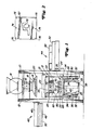
- the core machine is built about a frame including vertical members 10 and 12 which border a working area of the machine and provide support for machine components contained within and without the working area.
- the core machine has a sand storage hopper 14 with a butterfly valve 16 arranged beneath it for admitting sand into a blow chamber 18 which is bounded on its lower end by a blow plate 20 having blow tubes 19 projecting upwardly therefrom.
- An upper half of a core box or cope 21 is positioned and supported below and blow plate by a series of cope lift pins 22.
- the underside of cope 21 has an open recess 23.
- a lower half of the core box or drag 24, having a recess 25 open on its topside, is supported from a table 26.
- the height of the table is adjusted by a set of table lift cylinders 28 arranged about the periphery of the table.
- a set of cope lift cylinders 30 is arranged to the outside of the table cylinders and are used to adjust the height of the cope through the cope lift pins.
- a set of ejector cylinders 32 are grouped with the other cylinder sets and vertically adjust a set of ejector rods 34 which are part of an ejector assembly generally indicated as 36 and located in and about the drag.
- a shroud 38 houses a boost cylinder 40 and seals an area below the table to protect cylinder 40 from dirt and sand contamination.
- Gassing manifold assembly 42 is supported from member 12 by a beam 46 having a manifold guard 48 depending therefrom.
- a gassing manifold 50 is shown contained within the guard and can be shifted over into the frame area by an automatic slide mechanism (not shown).
- a rack beam 52 cantilevered from a set of vertical slide plates 54, provides support for pick-off finger assembly 44.
- One of slide plates 54 is attached to beam 52 and the other is attached to support member 10, with the plates cooperating to provide sliding support for rack beam 54 which prevents relative horizontal movement between beam 52 and support member 10 while allowing the pick-off finger assembly to be moved up or down by a hydraulic cylinder (not shown).
- a horizontally slidable assembly 56 rests at least partially on top rack beam 52 and is supported therefrom. The slidable assembly moves between an operating position within the working area as shown in Fig. 1 to a retracted position outside the working area and indicated by dashed lines 58.
- a hydraulic cylinder (not shown) controls inward and outward movement of the slide assembly.
- a set of pick-off fingers 60 depends from the slide assembly for removing a finished or semi-finished core from the ejector pins.
- a definning plate 62 also depends from the slide assembly 56 by a series of fin support rods 64.
- FIG. 1 depicts core 66 resting on a series of ejector pins 70 which together with a pin support plate 68, from which the pins project, and ejector rods 34 comprise ejector assembly 36.
- the ejector pin assembly ejects the core from the drag and holds the core above the drag on the tops of pins 70 for removal by the pick-off fingers 60.
- a set of guide pins 72 also project vertically from the drag and engage guide holes 74 on the definning plate when the slide plate assembly is lowered in a machine cycle hereinafter described.
- FIG. 2 shows a plan view of the definning plate 62.
- the definning plate has four points of support 76 at the four corners of the plate, to which rods 64 attach.
- Each guide hole 74 has a location, about the edge of the plate, midway between opposing pairs of the support points 76 .
- An aperture 78 having an outline setting the final tolerance of core 66, along the line of separation between the cope and the drag, is cut out of the center of the definning plate 62.
- the use of the definning plate in the machine cycle of the core machine will now be described in the context of a complete machine cycle for forming a core and removing it from the core box machine.
- the core is formed by a process well known to those skilled in the art such as a cold box process wherein sand coated with binder precursors are blown into a core box and treated with a gaseous catalyst to form a removable sand core.
- the various steps described herein will take place automatically as part of a predetermined machine cycle.
- the process begins by pressurizing the table lift cylinders 28 which pushes drag 24 upward against cope 21. Upper and lower faces of the drag and cope, respectively, are pushed together so that recesses 23 and 25 form a core cavity.
- the core box composed of the cope and the drag continues upward by action of the table cylinders until the top surface of cope 21 contacts blow plate 20.
- Extension of boost cylinder 40 at this time increases sealing pressure between the cope and the drag and the cope and the blow plate.
- a series of sensors (not shown) indicate when the connection between the blow plate and the upper surface of the cope and connection between the lower surface of the cope and the upper surface of the drag are sufficiently tight to prevent any leakage.
- butterfly valve 16 is closed to prevent back flow of air and sand into hopper 14. Two to three seconds of blow time fills the cavity with sand.
- the booster cylinder and the table cylinders retract to lower the top of the cope a small distance from the blow plate.
- Gassing manifold 50 is then shuttled into the space between the blow plate and the top of the cope and the table cylinders again extend to sandwich the gassing manifold tightly between the blow plate and the top of the cope.
- Booster cylinder 40 also extends to again increase the sealing pressure along the contact surfaces of the blow plate, gassing manifold, cope and drag.
- a gaseous catalyst in this case dimethyethylamine, passes into the gassing manifold, through a conduit and control system (not shown), which distributes the catalyst over the top surface of the cope and in turn throughout the resin coated sand contained within the core cavity.
- Gaseous catalyst passes through the sand and binder mixture for approximately eight to twenty seconds causing reaction of the phenolic resin with the polyisacyanate to form a relatively rigid urethane for solidifying the sand into a core.
- the gassing manifold only has outlets on its lower side so that the catalyst flows only into the cope. While catalyst is entering the cope, butterfly valve 16 automatically opens and allows coated sand to flow from storage in hooper 14 to chamber 18. After a predetermined amount of sand has entered the chamber, valve 16 automatically closes. During the sand loading process the upper surface of gassing manifold 50 seals the blow tubes 19 by contact with the blow plate 20 thereby preventing any loss of sand from blow chamber 18. Once the sand has settled in the blow chamber, blow tubes 19 prevent sand from emptying out of the chamber when the are beneath blow plate 20 is open.
- the core box is lowered by retraction of table cylinders 28.
- table cylinders 28 lowers the core box to a position where cope lift pins 22 contact the lower surface of cope 21 and hold the cope stationary with respect to the drag. Further retraction of the table cylinders allows the drag to move downward and separate from the cope under its own weight.
- ejector rods 34 contact ejector plate 68 so that the ejector pins 70 move upward relative to the drag. Relative upward movement of ejector pins 70 push core 66 out of drag recess 25.
- the timing of the ejector pin action in relation to drag movement and the elevation of the core above the drag is determined by the vertical position of ejector cylinders 32.
- the ejector pins hold the core 66 above the drag and a thin fin of sand 80 extends horizontally around the core about the parting seam of the cope and drag.
- pick-off finger assembly 56 is shuttled in from a retracted position 58 into the working area of the core machine. Once located in the working space, the guide holes 74 on the definner plate are vertically aligned with respective guide pins 72 projecting from the drag. Pick-off finger assembly is then lowered automatically to a point where guide pins 72 engage guide holes 74. Guide pin and hole engagement aligns the aperture of the definning plate with the core.
- lift cylinders 28 can be extended to bring the the cope and drag together. This action will initiate restart of the cycle.
Landscapes
- Engineering & Computer Science (AREA)
- Mechanical Engineering (AREA)
- Casting Devices For Molds (AREA)
- Molds, Cores, And Manufacturing Methods Thereof (AREA)
Applications Claiming Priority (2)
| Application Number | Priority Date | Filing Date | Title |
|---|---|---|---|
| US07/012,413 US4844141A (en) | 1987-02-09 | 1987-02-09 | Core defining apparatus and method |
| US12413 | 1987-02-09 |
Publications (2)
| Publication Number | Publication Date |
|---|---|
| EP0278716A2 true EP0278716A2 (fr) | 1988-08-17 |
| EP0278716A3 EP0278716A3 (fr) | 1988-12-21 |
Family
ID=21754849
Family Applications (1)
| Application Number | Title | Priority Date | Filing Date |
|---|---|---|---|
| EP88301032A Ceased EP0278716A3 (fr) | 1987-02-09 | 1988-02-08 | Machine et procédé pour la fabrication d'un noyau de moulage |
Country Status (2)
| Country | Link |
|---|---|
| US (1) | US4844141A (fr) |
| EP (1) | EP0278716A3 (fr) |
Cited By (2)
| Publication number | Priority date | Publication date | Assignee | Title |
|---|---|---|---|---|
| FR2650206A1 (fr) * | 1989-07-26 | 1991-02-01 | Erana Agustin Arana | Plateau de ramassage de noyaux de fonderie avec systeme d'ebarbage incorpore et deplacement transversal reglable pour pouvoir centrer les noyaux avec l'axe de manipulation |
| US5785107A (en) * | 1995-12-29 | 1998-07-28 | Georg Fischer Disa, Inc. | Apparatus and method for producing multiple cores |
Families Citing this family (4)
| Publication number | Priority date | Publication date | Assignee | Title |
|---|---|---|---|---|
| DE4002555C1 (fr) * | 1990-01-30 | 1991-05-29 | Adolf Hottinger Maschinenbau Gmbh, 6800 Mannheim, De | |
| US5911267A (en) * | 1996-11-13 | 1999-06-15 | Georg Fischer Disa, Inc. | Cope with bore for gassing cores |
| US6808010B2 (en) | 2001-03-13 | 2004-10-26 | Howmet Research Corporation | Method for treating ceramic cores |
| KR102226731B1 (ko) * | 2020-03-03 | 2021-03-11 | 진성민 | 주조용 코어성형장치 |
Family Cites Families (7)
| Publication number | Priority date | Publication date | Assignee | Title |
|---|---|---|---|---|
| US1735890A (en) * | 1925-10-29 | 1929-11-19 | Brune Rudolf | Core-peeling device for foundries |
| US2806265A (en) * | 1954-09-28 | 1957-09-17 | Walworth Co | Mechanism for removing excess material from shell molds |
| US2929120A (en) * | 1957-12-04 | 1960-03-22 | Gen Motors Corp | Method of definning sand cores |
| US2937421A (en) * | 1958-12-12 | 1960-05-24 | Taccone Pneumatic Foundry Equi | Machine for making molds for centrifugal castings |
| FR2382293A1 (fr) * | 1977-03-02 | 1978-09-29 | Pont A Mousson | Machine a fabriquer des noyaux de fonderie |
| NL7810752A (nl) * | 1977-11-04 | 1979-05-08 | Dansk Ind Syndikat | Kernbak. |
| US4445564A (en) * | 1981-11-10 | 1984-05-01 | Tsentralnoe Proektno-Konstruktorskoe I Tekhnologicheskoe Bjuro | Machine for making mould cores from flowable core sand mixtures in hot multiple core boxes |
-
1987
- 1987-02-09 US US07/012,413 patent/US4844141A/en not_active Expired - Fee Related
-
1988
- 1988-02-08 EP EP88301032A patent/EP0278716A3/fr not_active Ceased
Cited By (2)
| Publication number | Priority date | Publication date | Assignee | Title |
|---|---|---|---|---|
| FR2650206A1 (fr) * | 1989-07-26 | 1991-02-01 | Erana Agustin Arana | Plateau de ramassage de noyaux de fonderie avec systeme d'ebarbage incorpore et deplacement transversal reglable pour pouvoir centrer les noyaux avec l'axe de manipulation |
| US5785107A (en) * | 1995-12-29 | 1998-07-28 | Georg Fischer Disa, Inc. | Apparatus and method for producing multiple cores |
Also Published As
| Publication number | Publication date |
|---|---|
| EP0278716A3 (fr) | 1988-12-21 |
| US4844141A (en) | 1989-07-04 |
Similar Documents
| Publication | Publication Date | Title |
|---|---|---|
| CN110814284B (zh) | 活塞环铸造工艺 | |
| US4472092A (en) | Fabrication of metal shell golf club heads | |
| GB998865A (en) | Automatic core-making machine | |
| EP0278716A2 (fr) | Machine et procédé pour la fabrication d'un noyau de moulage | |
| CN109153069B (zh) | 脱箱造型机 | |
| US4840218A (en) | Automatic matchplate molding system | |
| US4890664A (en) | Automatic matchplate molding system | |
| US3878881A (en) | Method for producing and assembling cope and drag mold parts | |
| US3978186A (en) | Method for making a partitioned container | |
| EP0122116A2 (fr) | Machine pour la fabrication de moules en sable ou matériau semblable, à division horizontale sans châssis | |
| US4699199A (en) | Automated mold making system | |
| US3977821A (en) | Apparatus for making a partitioned container | |
| EP0040987B1 (fr) | Machine et procédé pour la fabrication de produits creux p.e. noyaux de fonderie en coquilles | |
| CN211389843U (zh) | 换向器自动压注设备 | |
| US4210194A (en) | Automatic method for producing molds using chemically bonded sands | |
| EP0443287A2 (fr) | Machine à mouler horizontale en deux parties de type chassis de dessous stationnaire pour noyaux | |
| US5329986A (en) | Automatic molding apparatus for forming sand casting molds | |
| CN209036936U (zh) | 一种可在内部实现浇口热切的模具 | |
| CN110814302B (zh) | 六工位砂型成型机 | |
| CN109530596B (zh) | 一种锻造模具 | |
| US4718474A (en) | Mold transfer mechanism for a molding machine | |
| US3192580A (en) | Apparatus and method for continuously producing investment molds | |
| JP2674330B2 (ja) | 砂型の湯口形成装置 | |
| US4074744A (en) | Automatic apparatus for producing molds using chemically bonded sands | |
| US4044818A (en) | Apparatus for forming sand molds |
Legal Events
| Date | Code | Title | Description |
|---|---|---|---|
| PUAI | Public reference made under article 153(3) epc to a published international application that has entered the european phase |
Free format text: ORIGINAL CODE: 0009012 |
|
| AK | Designated contracting states |
Kind code of ref document: A2 Designated state(s): DE FR GB IT |
|
| PUAL | Search report despatched |
Free format text: ORIGINAL CODE: 0009013 |
|
| AK | Designated contracting states |
Kind code of ref document: A3 Designated state(s): DE FR GB IT |
|
| 17P | Request for examination filed |
Effective date: 19890228 |
|
| 17Q | First examination report despatched |
Effective date: 19900202 |
|
| STAA | Information on the status of an ep patent application or granted ep patent |
Free format text: STATUS: THE APPLICATION HAS BEEN REFUSED |
|
| 18R | Application refused |
Effective date: 19900920 |