EP0278929A1 - Vorrichtung zur Einrichtung einer Strahlungsquelle, die unsichtbare Laserstrahlung emittiert - Google Patents
Vorrichtung zur Einrichtung einer Strahlungsquelle, die unsichtbare Laserstrahlung emittiert Download PDFInfo
- Publication number
- EP0278929A1 EP0278929A1 EP88850004A EP88850004A EP0278929A1 EP 0278929 A1 EP0278929 A1 EP 0278929A1 EP 88850004 A EP88850004 A EP 88850004A EP 88850004 A EP88850004 A EP 88850004A EP 0278929 A1 EP0278929 A1 EP 0278929A1
- Authority
- EP
- European Patent Office
- Prior art keywords
- monocular
- image
- light
- rays
- image converter
- Prior art date
- Legal status (The legal status is an assumption and is not a legal conclusion. Google has not performed a legal analysis and makes no representation as to the accuracy of the status listed.)
- Granted
Links
- 230000003287 optical effect Effects 0.000 claims abstract description 7
- 230000005540 biological transmission Effects 0.000 description 2
- 239000011521 glass Substances 0.000 description 1
- 238000005286 illumination Methods 0.000 description 1
- 230000035939 shock Effects 0.000 description 1
- 230000003595 spectral effect Effects 0.000 description 1
Images


Classifications
-
- G—PHYSICS
- G02—OPTICS
- G02B—OPTICAL ELEMENTS, SYSTEMS OR APPARATUS
- G02B23/00—Telescopes, e.g. binoculars; Periscopes; Instruments for viewing the inside of hollow bodies; Viewfinders; Optical aiming or sighting devices
- G02B23/02—Telescopes, e.g. binoculars; Periscopes; Instruments for viewing the inside of hollow bodies; Viewfinders; Optical aiming or sighting devices involving prisms or mirrors
- G02B23/10—Telescopes, e.g. binoculars; Periscopes; Instruments for viewing the inside of hollow bodies; Viewfinders; Optical aiming or sighting devices involving prisms or mirrors reflecting into the field of view additional indications, e.g. from collimator
-
- G—PHYSICS
- G02—OPTICS
- G02B—OPTICAL ELEMENTS, SYSTEMS OR APPARATUS
- G02B23/00—Telescopes, e.g. binoculars; Periscopes; Instruments for viewing the inside of hollow bodies; Viewfinders; Optical aiming or sighting devices
- G02B23/12—Telescopes, e.g. binoculars; Periscopes; Instruments for viewing the inside of hollow bodies; Viewfinders; Optical aiming or sighting devices with means for image conversion or intensification
Definitions
- the invention relates to an alignment means for a light source emitting invisible laser light.
- the means includes a monocular, a reflecting prism arranged to deflect a part of the emitted laser light and reflect it to the objective of the monocular, and an image converter for generating a visible image of the reflected laser light.
- the alignment means can be used, for example, in association with a laser alignment agent where the laser beams function as so-called guide beam.
- the image converter is situated inside the monocular, e.g. at the focal point of the light rays in the vicinity of the monocular eyepiece.
- the ordinary monocular image is give poor resolution and will be greenish, due to the restricted performance of the image converter with respect to resolution and spectral range. Small details at large distances will therefore merge together in the monocular image.
- the object of the present invention is to provide an alignment means of the kind mentioned in the introduction, but in which the problem with a greatly deteriorated monocular image is avoided. This is achieved by the image converter being situated spaced from the optical axis of the monocular and that only the reflected laser light is taken through the image converter, after which the now-visible laser image is superimposed on the ordinary monocular image.
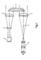
- Figure 1 illustrates a known alignment means
- Figure 2 illustrates a first embodiment of an alignment means in accordance with the invention
- Figure 3 illustrates a part of a second embodiment of an alignment means in accordance with the invention
- Figure 4 illustrates a part of the means according to Figure 3 seen from one side.
- a known alignment means is illustrated in Figure 1.
- a light source 1 generates visible laser light.
- Transmission optics including a divergent lens 2 and a convergent lens 3 provide a parallel ray bundle, which partially impinges on a prism 4.
- the prism is of the type which reflects incident rays in a manner such that the reflected rays, at least practically, will be parallel to the incident rays irrespective of their angle of incidence to the prism.
- a so-called cube corner prism is an example of a prism having such properties.
- a monocular with its optical axis 7 is provided with an eye piece 6 and an objective 5 and is arranged parallel to the laser rays.
- a part of the emitted laser beam is deflected with the aid of the prism into the monocular image field and is perceived in the monocular as an illuminated dot.
- the position of the dot in the monocular image shows the direction of the laser with an accuracy solely determined by the precision of the prism. The laser and the monocular thus do not need to be completely parallel.
- a first embodiment of an alignment means in accordance with the invention is illustrated in Figure 2.
- a light source 10 generates invisible laser light.
- the units 2-7 correspond to the units with the same numerical designations in Figure 1.
- the light rays in the monocular are collimated by a convergent lens 12 after having passed a first focal plane 11. Visible light then passes a first 13 and a second 14 beam splitter, and is focused by a convergent lens 15 towards a second focal plane 16.
- the beam splitter 13 is adapted to deflect the reflected and the invisible laser light.
- the deflected rays are focused on the input surface of an image converter 19 with the aid of a convergent lens 17 and a reflecting member 18.
- the image converter is thus situated spaced from the optical axis 7 of the monocular and is therefore solely passed through by the laser light.
- the light rays from the output surface of the image converter, these rays representing the now-visible and greenish image of the laser spot, are reflected by a reflecting member 20, collimated by a convergent lens 21 and are then incident on the beam splitter 14.
- the reflecting members 18 and 20 may be such as prisms or mirrors.
- the beam splitter 14 is adapted to pass the visible light through from the beam splitter 13 and deflect the light from the image converter 19.
- Both beam splitters 13 and 14, which are also known as dichroic filters, may be so-called beam splitter cubes, and are thus not identical since the beam splitter 14 is adapted to pass visible light through, which is incident on one side of it, and deflect the greenish light from the image converter incident on its other side.
- the beam splitter 13 is adapted to let through all visible light and only to deflect the invisible laser light.
- the light from the image converter 18 deflected in the image splitter 14 is focused together with the light rays from the beam splitter 13 towards a second focal plane 16 in the monocular and is thus superimposed on the ordinary monocular image.
- the image converter 19 or any of the units 13, 14, 17-21 may be given incorrect alignment, resulting in incorrect information as to the actual direction of the laser light source 10.
- a glass plate with clear marking e.g. cross-hairs
- two images of the cross-hairs are obtained at the second focal plane 16 in the monocular.
- One image is obtained directly in the monocular via the lenses and beam splitters 12-15, while the other image is obtained with the aid of the image converter 19.
- the means is adjusted by one of the units 13, 14, 17-21 being adjusted so that both images coincide. Since continuous illumination is required in the calibration, a light source 22 giving continuous light is used in this case, and not the laser 10 which only provides short light pulses.
- the light source 22 can convetionally be a light emitting diode, situated to one side of the focal plane 11.
- Figures 3 and 4 Part of a second embodiment of an alignment means in accordance with the invention is illustrated in Figures 3 and 4, Figure 3 being a plan of the means and Figure 4 a side-view from the right of a part of the means according to Figure 3.
- the laser light source and transmission optics are not depicted in the Figures.
- the members having direct counterpart in previous Figures have been provided with the same reference numerals as in these Figures.
- Members which have a principly similar task as the members in Figure 2 have been provided with reference numerals exceeding the value of the corresponding numerals in Figure 2 by 100.
- the beam splitter comprises a beam splitter cube 30 having a beam splitting surface denoted by a diagonal line across the cube in Figure 3, and extending at right angles to the plane of the paper.
- the light rays in the monocular are collimated by a convergent lens 112 and are incident on the beam splitter 30.
- the latter is adapted to let through visible light incident from the right in Figure 3, i.e. incident to the plane of the paper in Figure 4.
- the light is then incident on a convergent lens 115, which focuses it towards the eyepiece 6.
- the invisible light is deflected in the beam splitter 30 towards a convergent lens 117 and further towards a prism 31, which in turn reflects the light towards a prism 32.
- the prism 32 is under the prism 31 and is therefore not visible in this Figure.
- the light is reflected in the prism 32 and is focused on the input surface of the image converter 19, which is hidden to a large extent in Figure 3.
- the image converter is also situated spaced from the monocular axis 7, and is thus only passed through by light rays from the laser source.
- the visible light from the output of the image converter is reflected by two prisms 33 and 34 towards a collimater lens 121 and are then incident on the beam splitter 30.
- the latter is also adapted to deflect the greenish light coming from the lens 121, this light coming from the image converter 19, to the left in Figure 1, i.e. in the plane of the paper in Figure 4.
- the light is then incident on the lens 115 and is superimposed on the ordinary monocular image.
- the image converter can be used together with a monocular with more than two focal planes. It is also conceivable to place the beam splitters in ray bundles which are not parallel.
Landscapes
- Physics & Mathematics (AREA)
- Astronomy & Astrophysics (AREA)
- General Physics & Mathematics (AREA)
- Optics & Photonics (AREA)
- Telescopes (AREA)
- Laser Surgery Devices (AREA)
- Optical Radar Systems And Details Thereof (AREA)
Applications Claiming Priority (2)
| Application Number | Priority Date | Filing Date | Title |
|---|---|---|---|
| SE8700469 | 1987-02-06 | ||
| SE8700469A SE456456B (sv) | 1987-02-06 | 1987-02-06 | Inriktningsanordning for en ljuskella som utsender icke synligt laserljus |
Publications (2)
| Publication Number | Publication Date |
|---|---|
| EP0278929A1 true EP0278929A1 (de) | 1988-08-17 |
| EP0278929B1 EP0278929B1 (de) | 1992-03-18 |
Family
ID=20367427
Family Applications (1)
| Application Number | Title | Priority Date | Filing Date |
|---|---|---|---|
| EP88850004A Expired EP0278929B1 (de) | 1987-02-06 | 1988-01-12 | Vorrichtung zur Einrichtung einer Strahlungsquelle, die unsichtbare Laserstrahlung emittiert |
Country Status (4)
| Country | Link |
|---|---|
| US (1) | US4850694A (de) |
| EP (1) | EP0278929B1 (de) |
| DE (1) | DE3869152D1 (de) |
| SE (1) | SE456456B (de) |
Cited By (6)
| Publication number | Priority date | Publication date | Assignee | Title |
|---|---|---|---|---|
| WO1992003754A1 (en) * | 1990-08-13 | 1992-03-05 | B.V. Optische Industrie 'de Oude Delft' | Combined day viewing and night viewing telescope |
| WO1992016864A1 (en) * | 1991-03-22 | 1992-10-01 | Gec Ferranti Defence Systems Limited | Infrared optical system |
| GB2275543A (en) * | 1992-10-16 | 1994-08-31 | Secr Defence | Laser beam alignment device |
| EP1126299A1 (de) * | 2000-02-15 | 2001-08-22 | Leica Geosystems AG | Gerät mit Nachtsichtfähigkeit |
| FR2960065A1 (fr) * | 2010-05-17 | 2011-11-18 | Sagem Defense Securite | Dispositif combine d'observation et d'emission, et procede de visualisation d'une direction d'emission d'un tel dispositif |
| CN104122663A (zh) * | 2014-07-14 | 2014-10-29 | 山东神戎电子股份有限公司 | 一种便于微调出光光轴的激光照明器底座 |
Families Citing this family (6)
| Publication number | Priority date | Publication date | Assignee | Title |
|---|---|---|---|---|
| US5047638A (en) * | 1989-06-28 | 1991-09-10 | Cameron Jeffery A | Passive boresighting system |
| US6836329B1 (en) | 2003-07-09 | 2004-12-28 | International Business Machines Corporation | Real time IR optical sensor |
| CN116584010A (zh) * | 2020-12-16 | 2023-08-11 | 西默有限公司 | 用于光学部件对准的装置和方法 |
| US11572433B2 (en) | 2021-03-12 | 2023-02-07 | Covestro Llc | In-situ formed polyols, a process for their preparation, foams prepared from these in-situ formed polyols and a process for their preparation |
| CN113155049A (zh) * | 2021-03-25 | 2021-07-23 | 深圳市海塞姆科技有限公司 | 光路系统及单目三维图像采集系统的固定方法 |
| US11718705B2 (en) | 2021-07-28 | 2023-08-08 | Covestro Llc | In-situ formed polyether polyols, a process for their preparation, and a process for the preparation of polyurethane foams |
Citations (4)
| Publication number | Priority date | Publication date | Assignee | Title |
|---|---|---|---|---|
| US3712702A (en) * | 1966-12-21 | 1973-01-23 | Leitz Ernst Gmbh | Telescopic sight for daylight and night observation |
| DE2536878A1 (de) * | 1975-08-19 | 1977-02-24 | Siemens Ag | Optronisches system mit einem von einer justierhilfe gebrauch machenden optronischen geraet |
| GB2088082A (en) * | 1980-11-02 | 1982-06-03 | Technion Res & Dev Foundation | Night-vision equipment |
| GB2119125A (en) * | 1982-04-23 | 1983-11-09 | Marconi Co Ltd | Control of brightness in optical sights |
Family Cites Families (2)
| Publication number | Priority date | Publication date | Assignee | Title |
|---|---|---|---|---|
| BE818297A (fr) * | 1973-08-03 | 1974-11-18 | Dispositif optoelectronique d'indication visuelle | |
| US4653879A (en) * | 1985-03-01 | 1987-03-31 | Fjw Industries, Inc. | Compact see-through night vision goggles |
-
1987
- 1987-02-06 SE SE8700469A patent/SE456456B/sv not_active IP Right Cessation
-
1988
- 1988-01-12 DE DE8888850004T patent/DE3869152D1/de not_active Expired - Lifetime
- 1988-01-12 EP EP88850004A patent/EP0278929B1/de not_active Expired
- 1988-02-04 US US07/152,241 patent/US4850694A/en not_active Expired - Fee Related
Patent Citations (4)
| Publication number | Priority date | Publication date | Assignee | Title |
|---|---|---|---|---|
| US3712702A (en) * | 1966-12-21 | 1973-01-23 | Leitz Ernst Gmbh | Telescopic sight for daylight and night observation |
| DE2536878A1 (de) * | 1975-08-19 | 1977-02-24 | Siemens Ag | Optronisches system mit einem von einer justierhilfe gebrauch machenden optronischen geraet |
| GB2088082A (en) * | 1980-11-02 | 1982-06-03 | Technion Res & Dev Foundation | Night-vision equipment |
| GB2119125A (en) * | 1982-04-23 | 1983-11-09 | Marconi Co Ltd | Control of brightness in optical sights |
Cited By (8)
| Publication number | Priority date | Publication date | Assignee | Title |
|---|---|---|---|---|
| WO1992003754A1 (en) * | 1990-08-13 | 1992-03-05 | B.V. Optische Industrie 'de Oude Delft' | Combined day viewing and night viewing telescope |
| WO1992016864A1 (en) * | 1991-03-22 | 1992-10-01 | Gec Ferranti Defence Systems Limited | Infrared optical system |
| US5513034A (en) * | 1991-03-22 | 1996-04-30 | Gec Marconi Avionics (Holdings) Limited | Infrared optical system |
| GB2275543A (en) * | 1992-10-16 | 1994-08-31 | Secr Defence | Laser beam alignment device |
| EP1126299A1 (de) * | 2000-02-15 | 2001-08-22 | Leica Geosystems AG | Gerät mit Nachtsichtfähigkeit |
| US6369941B2 (en) | 2000-02-15 | 2002-04-09 | Leica Geosystems Ag | Device with night vision capability |
| FR2960065A1 (fr) * | 2010-05-17 | 2011-11-18 | Sagem Defense Securite | Dispositif combine d'observation et d'emission, et procede de visualisation d'une direction d'emission d'un tel dispositif |
| CN104122663A (zh) * | 2014-07-14 | 2014-10-29 | 山东神戎电子股份有限公司 | 一种便于微调出光光轴的激光照明器底座 |
Also Published As
| Publication number | Publication date |
|---|---|
| DE3869152D1 (de) | 1992-04-23 |
| US4850694A (en) | 1989-07-25 |
| SE8700469L (sv) | 1988-08-07 |
| SE8700469D0 (sv) | 1987-02-06 |
| EP0278929B1 (de) | 1992-03-18 |
| SE456456B (sv) | 1988-10-03 |
Similar Documents
| Publication | Publication Date | Title |
|---|---|---|
| US7413311B2 (en) | Speckle reduction in laser illuminated projection displays having a one-dimensional spatial light modulator | |
| EP0746865B1 (de) | System zur fluoreszenzabbildung unter verwendung eines objektivs mit makroabtastung | |
| US5288987A (en) | Autofocusing arrangement for a stereomicroscope which permits automatic focusing on objects on which reflections occur | |
| EP0278929B1 (de) | Vorrichtung zur Einrichtung einer Strahlungsquelle, die unsichtbare Laserstrahlung emittiert | |
| DE69922139T2 (de) | Strahlteiler mit versetzten oeffnungen fuer sender/empfaenger in einem optomechanischen lasersystem | |
| CN110998359B (zh) | 用于激光雷达系统的光学装置,激光雷达系统和工作设备 | |
| US4723845A (en) | Optical apparatus for the detection of position | |
| GB1600191A (en) | Electrooptical range finders | |
| CN116500771B (zh) | 一种正像系统及激光测距双筒望远镜 | |
| JP2008039600A (ja) | ダイクロイックプリズムによる光分割した測量機 | |
| JP2000097699A5 (de) | ||
| GB2212040A (en) | Light aiming device for medical or dental X-ray equipment | |
| US3721488A (en) | Focusing arrangment for afocal telescopes | |
| US5608564A (en) | Scanning objective | |
| US5084616A (en) | Scanner having horizontal synchronizing signal generator with prism light diameter reducing means | |
| WO1990000755A1 (en) | Achromatic scanning system | |
| CN220137485U (zh) | 一种正像系统及激光测距双筒望远镜 | |
| EP0173345B1 (de) | Verfahren und Vorrichtung zur gleichzeitigen Beobachtung eines transparenten Objektes aus zwei Richtungen | |
| US5225929A (en) | Device for producing a light spot in a microscope | |
| US20040164221A1 (en) | Optical inspection system having an internal rangefinder | |
| US3506355A (en) | Compact arrangement of two optical objectives for transmitting and receiving radiation | |
| GB2147716A (en) | Adapter for illumination or laser radiation for surgical microscopes | |
| JPH11153754A (ja) | 照明光学系及びアキシコンプリズム | |
| US10473905B2 (en) | Microscope having an optical coherence tomography device | |
| JP3131826B2 (ja) | 正立・分岐光学系 |
Legal Events
| Date | Code | Title | Description |
|---|---|---|---|
| PUAI | Public reference made under article 153(3) epc to a published international application that has entered the european phase |
Free format text: ORIGINAL CODE: 0009012 |
|
| AK | Designated contracting states |
Kind code of ref document: A1 Designated state(s): DE FR GB IT |
|
| 17P | Request for examination filed |
Effective date: 19880908 |
|
| 17Q | First examination report despatched |
Effective date: 19910117 |
|
| GRAA | (expected) grant |
Free format text: ORIGINAL CODE: 0009210 |
|
| AK | Designated contracting states |
Kind code of ref document: B1 Designated state(s): DE FR GB IT |
|
| REF | Corresponds to: |
Ref document number: 3869152 Country of ref document: DE Date of ref document: 19920423 |
|
| ITF | It: translation for a ep patent filed | ||
| ET | Fr: translation filed | ||
| PLBE | No opposition filed within time limit |
Free format text: ORIGINAL CODE: 0009261 |
|
| STAA | Information on the status of an ep patent application or granted ep patent |
Free format text: STATUS: NO OPPOSITION FILED WITHIN TIME LIMIT |
|
| 26N | No opposition filed | ||
| PGFP | Annual fee paid to national office [announced via postgrant information from national office to epo] |
Ref country code: FR Payment date: 19990111 Year of fee payment: 12 |
|
| PGFP | Annual fee paid to national office [announced via postgrant information from national office to epo] |
Ref country code: GB Payment date: 19990114 Year of fee payment: 12 |
|
| PGFP | Annual fee paid to national office [announced via postgrant information from national office to epo] |
Ref country code: DE Payment date: 19990115 Year of fee payment: 12 |
|
| PG25 | Lapsed in a contracting state [announced via postgrant information from national office to epo] |
Ref country code: GB Free format text: LAPSE BECAUSE OF NON-PAYMENT OF DUE FEES Effective date: 20000112 |
|
| GBPC | Gb: european patent ceased through non-payment of renewal fee |
Effective date: 20000112 |
|
| PG25 | Lapsed in a contracting state [announced via postgrant information from national office to epo] |
Ref country code: FR Free format text: LAPSE BECAUSE OF NON-PAYMENT OF DUE FEES Effective date: 20000929 |
|
| PG25 | Lapsed in a contracting state [announced via postgrant information from national office to epo] |
Ref country code: DE Free format text: LAPSE BECAUSE OF NON-PAYMENT OF DUE FEES Effective date: 20001101 |
|
| REG | Reference to a national code |
Ref country code: FR Ref legal event code: ST |
|
| PG25 | Lapsed in a contracting state [announced via postgrant information from national office to epo] |
Ref country code: IT Free format text: LAPSE BECAUSE OF NON-PAYMENT OF DUE FEES;WARNING: LAPSES OF ITALIAN PATENTS WITH EFFECTIVE DATE BEFORE 2007 MAY HAVE OCCURRED AT ANY TIME BEFORE 2007. THE CORRECT EFFECTIVE DATE MAY BE DIFFERENT FROM THE ONE RECORDED. Effective date: 20050112 |