EP0279301A1 - Geschoss - Google Patents
Geschoss Download PDFInfo
- Publication number
- EP0279301A1 EP0279301A1 EP88101728A EP88101728A EP0279301A1 EP 0279301 A1 EP0279301 A1 EP 0279301A1 EP 88101728 A EP88101728 A EP 88101728A EP 88101728 A EP88101728 A EP 88101728A EP 0279301 A1 EP0279301 A1 EP 0279301A1
- Authority
- EP
- European Patent Office
- Prior art keywords
- cartridge
- opening
- propellant charge
- projectile
- base
- Prior art date
- Legal status (The legal status is an assumption and is not a legal conclusion. Google has not performed a legal analysis and makes no representation as to the accuracy of the status listed.)
- Granted
Links
Images


Classifications
-
- F—MECHANICAL ENGINEERING; LIGHTING; HEATING; WEAPONS; BLASTING
- F42—AMMUNITION; BLASTING
- F42B—EXPLOSIVE CHARGES, e.g. FOR BLASTING, FIREWORKS, AMMUNITION
- F42B5/00—Cartridge ammunition, e.g. separately-loaded propellant charges
- F42B5/02—Cartridges, i.e. cases with charge and missile
- F42B5/10—Cartridges, i.e. cases with charge and missile with self-propelled bullet
Definitions
- the invention relates to a projectile with a cartridge, wherein a passage opening of the cartridge base contains a squib which can be struck from the outside and which ignites a condensed propellant charge provided in the interior of the cartridge, the gases of which flow into the cartridge through at least one side gas outlet opening of the propellant charge accelerate the projectile.
- Such bullets are known for example from AT-PSen 371 596 and 374 583.
- the propellant charge cartridge is inserted into the opening in the base of the cartridge and the propellant charge covered by the squib to the outside.
- the struck detonator ignites the damn propellant charge, the gases of which escape into the gas pressure chamber, so that the bullet is released from the cartridge after a corresponding pressure has been built up. Since the gas outlet openings are removed from the burning side of the propellant charge bordering the squib, the overflowing gases entrain propellant charge particles, which thereby escape combustion.
- the portion that is clearly visible in the cartridge after firing is relatively large. Experiments have shown that fluctuations of 15% or more can result in the launch speed, which significantly impair the target safety.
- the invention has now set itself the task of creating a projectile of the type mentioned, which is easier to manufacture, and in which a largely constant initial speed is preferably achieved by a substantially more complete combustion of the propellant charge and the target safety is improved.
- the propellant charge cartridge is connected to the projectile and on the side facing the cartridge bottom has a cartridge bottom effecting the insulation of the propellant charge, which is provided with an ignition opening coaxial with the passage opening in the cartridge bottom.
- the arrangement of the propellant charge cartridge on the floor significantly simplifies the manufacture of the cartridge, since these, including their very small passage opening, can be produced in a single non-cutting operation, for example by deep drawing, while the manufacture of the floor or its base part is only insignificantly complicated.
- a preferred embodiment provides that the propellant charge cartridge is screwed into a protruding threaded connector of the base part.
- the propellant charge cartridge is pot-shaped, has an external thread and contains a cover that covers the ignition opening and can be destroyed by the ignition jet.
- a first preferred embodiment, in which the propellant charge cartridge has a plurality of lateral gas outlet openings, provides that the area of the cartridge base surrounding the ignition opening approximately touches the area of the cartridge base surrounding the passage opening.
- the ignition jet of the squib penetrates through the ignition opening into the propellant charge cartridge, the installation of the ignition opening surrounding area on the base of the cartridge preventing the propellant gases from escaping directly through the ignition opening. Since the propellant charge burns off from the ignition opening, there is initially a strong insulation until the cross section of the combustion has reached the gas outlet openings on the side.
- the ignition opening is preferably smaller than the passage opening in the cartridge base and has, for example, only about half its diameter.
- the lateral gas outlet openings are arranged near the base of the cartridge in the peripheral wall of the propellant cartridge. After the small, first part of the propellant charge has burned off, further charge particles pass through, which are entrained by the resulting gases from the cartridge, so that the propellant charge that burns down into the depth of the cartridge, so that they are also burned. A practically complete combustion is thus achieved, so that the achievable initial speed is essentially constant.
- a similar effect is achieved in another embodiment in that a ring of gas outlet openings is arranged in the cartridge base outside the contact area surrounding the ignition opening, the region of the cartridge base surrounding the through opening being formed inwards up to the propellant charge cartridge.
- the propellant charge cartridge is arranged at a distance from the base of the cartridge, and the ignition opening of the base of the cartridge, which is coaxial with the passage opening of the cartridge base, also forms the gas outlet opening.
- the distance to the cartridge floor ensures that the propellant gases escape into the gas pressure chamber. Since the ignition jet of the squib penetrates into the propellant charge cartridge through the gas outlet opening, all charge particles that are entrained by the resulting gases from the cartridge are completely burned.
- the ignition opening forming the gas outlet opening is preferably larger than the passage opening in the base of the cartridge, for example by 2 to 3 times.
- a further approximation to a constant initial speed can be achieved by deepening the circumference of the Ge lap can be reached, into which the edge area of the cartridge is pressed.
- the resulting form fit between the cartridge and the projectile requires a certain gas pressure to destroy it, so that maximum pressure build-up is achieved.
- a projectile 1 of any kind such as an explosive grenade with a delay detonator or impact detonator, a smoke grenade, a practice projectile, etc. is inserted into a cartridge 3, a gas pressure chamber 10 being formed between the base part 2 of the projectile 1 and the cartridge base 4.
- the floor 1 is or the like with a circumferential groove 11. to form a positive connection and an edge region 12 of the cartridge 3, which, as shown, is achieved by crimping the edge or by means of embossments distributed over the circumference or by means of an annular bead.
- the cartridge 3 is deep-drawn, for example, from an aluminum alloy, and has a central passage opening 5 in a region 16 of the cartridge base 4, into which a squib 9 is inserted.
- a threaded connector 13 is formed, into which a propellant charge cartridge 6 is inserted, which contains the propellant charge 7.
- the propellant charge cartridge in the cartridge base 17 has a central ignition opening 15 of small diameter and lateral gas outlet openings 8, which are provided on the inside by a cover 14 made of easily destructible material, for example made of paper, plastic or the like. are locked to prevent the falling out To prevent propellant charge 7.
- the cartridge base 17 touches the cartridge base 4, or at most has a small distance from it that results from production inaccuracies.
- the ignition jet of the squib 9 which is acted upon from the outside, strikes the propellant charge 7 through the openings 5 and 15, the cover 14 being destroyed.
- the propellant charge 7 is thus ignited at the ignition opening 15, and because of the very small gap between the cartridge base 17 and the area 16 of the cartridge base 4, there is initially a high level of insulation.
- the developing propellant gases then exit into the gas pressure chamber 10 through the side gas outlet openings 8 arranged near the cartridge base 17.
- Propellant particles entrained by the propellant gases from the interior of the propellant charge cartridge 6 must thereby pass through the cross-section of the firing which spreads from the ignition opening 15, so that their complete combustion is ensured.
- the gas outlet openings 8 are arranged in a ring on the cartridge base 17, with the same configuration, and run obliquely outwards.
- the area 16 of the cartridge base 4, which protrudes somewhat inwards, ensures contact with the area of the cartridge base 17 surrounding the ignition opening.
- the propellant charge cartridge 6 is smaller than the inner height of the cartridge 3, so that the cartridge base 17 lies at a distance from the cartridge base 4.
- the ignition opening 15 is enlarged and at the same time forms the only gas outlet opening 8 ⁇ .
- the propellant charge 7 is thus ignited in the gas outlet opening 8 ⁇ and the developing propellant gases emerge through the opening 8 ⁇ into the gas pressure chamber 10. From the moment of ignition, propellants must be carried along by the propellant gases Charge particles pass through the firing cross-section which extends from the opening 8 ⁇ so that their complete combustion is ensured.
- the initial velocity given to a projectile 1 according to the invention after the positive locking 11, 12 breaks, is subject to only slight fluctuations, since an approximately constant gas pressure can be achieved, and the target reliability is significantly improved.
Landscapes
- Engineering & Computer Science (AREA)
- General Engineering & Computer Science (AREA)
- Pharmaceuticals Containing Other Organic And Inorganic Compounds (AREA)
- Hydrogenated Pyridines (AREA)
- Toys (AREA)
- Aiming, Guidance, Guns With A Light Source, Armor, Camouflage, And Targets (AREA)
- Air Bags (AREA)
Abstract
Description
- Die Erfindung betrifft ein Geschoß mit einer Kartusche, wobei eine Durchtrittsöffnung des Kartuschenbodens eine von außen anschlagbare Zündpille enthält, die eine im Inneren der Kartusche vorgesehene verdämmte Treibladung zündet, deren durch mindestens eine seitliche Gasaustrittsöffnung der Treibladungspatrone in die Kartusche strömenden Gase das Geschoß beschleunigen.
- Derartige Geschosse sind beispielsweise durch die AT-PSen 371 596 und 374 583 bekannt. Die Treibladungspatrone ist hiebei in die Öffnung des Kartuschenbodens einegesetzt, und die enthaltene Treibladung durch die Zündpille nach außen überdeckt. In den in der Kartusche gebildeten Gasdruckraum, der durch das eingesetzte Geschoß geschlossen ist, münden aus der Treibladungspatrone seitlich mehrere Gasaustrittsöffnungen. Die angeschlagene Zündpille zündet die verdämmte Treibladung, deren Gase in den Gasdruckraum entweichen, sodaß sich nach Aufbau eines entsprechenden Druckes das Geschoß aus der Kartusche löst. Da die Gasaustrittsöffnungen von der an die Zündpille grenzenden Anbrennseite der Treibladung entfernt sind, reißen die überströmenden Gase Treibladungspartikel mit, die dadurch der Verbrennung entgehen. Deren nach dem Abschuß in der Kartusche deutlich sichtbarer Anteil ist relativ groß. Versuche haben ergeben, daß sich dadurch in der Abschußgeschwindigkeit Schwankungen von 15 % und mehr ergeben können, die die Zielsicherheit maßgeblich verschlechtern.
- Die Erfindung hat es sich nun zur Aufgabe gestellt, ein Geschoß der eingangs genannten Art zu schaffen, das einfacher herzustellen ist, und bei dem bevorzugt durch eine wesentlich vollständigere Verbrennung der Treibladung eine weitgehend konstante Anfangsgeschwindigkeit erreicht und die Zielsicherheit verbessert wird.
- Erfindungsgemäß wird diese Aufgabe nun dadurch gelöst, daß die Treibladungspatrone mit dem Geschoß verbunden ist und an der zum Kartuschenboden gewandten Seite einen die Verdämmung der Treibladung bewirkenden Patronenboden aufweist, der mit einer mit der Durchtrittsöffnung im Kartuschenboden koaxialen Zündöffnung versehen ist.
- Die Anordnung der Treibladungspatrone am Geschoß vereinfacht die Herstellung der Kartusche wesentlich, da diese einschließlich ihrer sehr kleinen Durchtrittsöffnung in einem einzigen spanlosen Arbeitsgang, etwa durch Tiefziehen fertigbar sind, während die Herstellung des Geschosses bzw. dessen Bodenteiles nur unwesentlich erschwert wird. Eine bevorzugte Ausführung sieht nämlich vor, daß die Treibladungspatrone in einen abstehenden Gewindestutzen des Bodenteiles eingeschraubt ist. Die Treibladungspatrone ist hiezu topfförmig ausgebildet, mit einem Außengewinde versehen und enthält eine die Zündöffnung überdeckende Abdeckung, die durch den Zündstrahl zerstörbar ist.
- Eine erste bevorzugte Ausführung, in der die Treibladungspatrone mehrere seitliche Gasaustrittsöffnungen aufweist, sieht vor, daß der die Zündöffnung umgebende Bereich des Patronenbodens den die Durchtrittsöffnung umgebenden Bereich des Kartuschenbodens annähernd berührt. Der Zündstrahl der Zündpille dringt durch die Zündöffnung in die Treibladungspatrone ein, wobei die Anlage des Zündöffnungsumgebungsbereiches am Kartuschenboden den direkten Austritt der Treibgase durch die Zündöffnung verhindert. Da die Treibladung von der Zündöffnung her abbrennt, findet vorerst eine starke Verdämmung statt, bis der Brennquerschnitt die seitlichen Gasaustrittsöffnungen erreicht hat. Bevorzugt ist die Zündöffnung kleiner als die Durchtrittsöffnung im Kartuschenboden, und weist beispielsweise etwa nur deren halben Durchmesser auf.
- Dabei kann weiters vorgesehen sein, daß die seitlichen Gasaustrittsöffnungen nahe dem Patronenboden in der Umfangswand der Treibladungspatrone angeordnet sind. Nach dem Abbrennen des geringen, ersten Teiles der Treibladung passieren weitere Ladungspartikel, die von den entstehenden Gasen aus der Patrone mitgerissen werden, damit zwangsläufig die in die Tiefe der Patrone abbrennende Treibladung, sodaß sie ebenfalls verbrannt werden. Es wird damit eine praktisch vollständige Verbrennung erreicht, sodaß die erzielbare Anfangsgeschwindigkeit im wesentlichen konstant ist. Ein ähnlicher Effekt wird in einer anderen Ausführung dadurch erreicht, daß ein Kranz von Gasaustrittsöffnungen im Patronenboden außerhalb des die Zündöffnung umgebenden Berührungsbereiches angeordnet ist, wobei der die Durchtrittsöffnung umgebende Bereich des Kartuschenbodens nach innen bis zur Treibladungspatrone vorstehend ausgebildet ist.
- In einer weiteren Ausführung ist vorgesehen, daß die Treibladungspatrone mit Abstand zum Kartuschenboden angeordnet ist, und die mit der Durchtrittsöffnung des Kartuschenbodens koaxiale Zündöffnung des Patronenbodens auch die Gasaustrittsöffnung bildet.
- Nach dieser Ausführung stellt der Abstand zum Kartuschenboden den Austritt der Treibgase in den Gasdruckraum sicher. Da der Zündstrahl der Zündpille hier durch die Gasaustrittsöffnung in die Treibladungspatrone eindringt, werden sämtliche Ladungspartikel, die von den entstehenden Gasen aus der Patrone mitgerissen werden, vollständig verbrannt. Die die Gasaustrittsöffnung bildende Zündöffnung ist in dieser Ausführung bevorzugt größer als die Durchtrittsöffnung im Kartuschenboden, beispielsweise um das 2- bis 3-fache.
- Eine weitere Annäherung an eine konstante Anfangsgeschwindigkeit kann noch durch eine Umfangsvertiefung des Ge schosses erreicht werden, in die der Randbereich der Kartusche eingedrückt ist. Der hierdurch gegebene Formschluß zwischen der Kartusche und dem Geschoß erfordert einen bestimmten Gasdruck zu seiner Zerstörung, sodaß maximaler Druckaufbau erreicht wird.
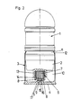
- Nachstehend werden drei Ausführungsbeispiele der Erfindung an Hand der Figuren der beiliegenden Zeichnungen näher beschrieben, die jeweils einen Teillängsschnitt durch ein in eine Kartusche eingesetztes Geschoß zeigen.
- Ein Geschoß 1 beliebiger Art, etwa eine Sprenggranate mit Verzögerungszünder oder Aufschlagzünder, eine Rauchgranate, ein Übungsgeschoß, usw. ist in eine Kartusche 3 eingesetzt, wobei zwischen dem Bodenteil 2 des Geschosses 1 und dem Kartuschenboden 4 ein Gasdruckraum 10 gebildet ist. Das Geschoß 1 ist mit einer Umfangsrille 11 od.dgl. zur Ausbildung eines Formschlusses und einem Randbereich 12 der Kartusche 3 versehen, der wie dargestellt, mittels einer Einbördelung des Randes bzw. mittels über den Umfang verteilter Prägungen oder mittels einer ringförmigen Sicke erzielt wird.
- Die Kartusche 3 ist beispielsweise aus einer Aluminiumlegierung tiefgezogen, und weist eine mittlere Durchtrittsöffnung 5 in einem Bereich 16 des Kartuschenbodens 4 auf, in die eine Zündpille 9 eingesetzt ist. Am Bodenteil 2 des Geschosses 1 ist ein Gewindestutzen 13 angeformt, in den eine Treibladungspatrone 6 eingesetzt ist, die die Treibladung 7 enthält.
- Gemäß Fig. 1 weist die Treibladungspatrone im Patronenboden 17 eine mittige Zündöffnung 15 geringen Durchmessers und seitliche Gasaustrittsöffnungen 8 auf, die an der Innenseite durch eine Abdeckung 14 aus leicht zerstörbarem Material, beispielsweise aus Papier, Kunststoff od.dgl. verschlossen sind, um das Herausfallen der Treibladung 7 zu verhindern. Der Patronenboden 17 berührt den Kartuschenboden 4, bzw. weist höchstens einen durch Produktionsungenauigkeiten sich ergebenden geringen Abstand dazu auf. Der Zündstrahl der von außen beaufschlagten Zündpille 9 trifft durch die Öffnungen 5 und 15 auf die Treibladung 7, wobei die Abdeckung 14 zerstört wird. Die Treibladung 7 wird somit an der Zündöffnung 15 gezündet, wobei aufgrund des sehr geringen Spaltes zwischen dem Patronenboden 17 und dem Bereich 16 des Kartuschenbodens 4 vorerst eine starke Verdämmung gegeben ist. Die sich entwickelnden Treibgase treten dann durch die seitlichen, nahe dem Patronenboden 17 angeordneten Gasaustrittsöffnungen 8 in den Gasdruckraum 10 aus. Von den Treibgasen mitgerissene Treibladungspartikel aus dem Inneren der Treibladungspatrone 6 müssen dadurch den von der Zündöffnung 15 in die Tiefe sich ausbreitenden Brennquerschnitt passieren, sodaß deren restlose Verbrennung sichergestellt ist.
- Entsprechend Fig. 2 sind bei sonst gleicher Ausgestaltung die Gasaustrittsöffnungen 8 in einem Kranz am Patronenboden 17 angeordnet, und verlaufen schräg nach außen. Der etwas nach innen hochstehende Bereich 16 des Kartuschenbodens 4 stellt dabei die Berührung mit dem die Zündöffnung umgebenden Bereich des Patronenbodens 17 sicher.
- In der Ausführung nach Fig. 3 ist die Treibladungspatrone 6 kleiner als die Innenhöhe der Kartusche 3, sodaß der Patronenboden 17 mit Abstand zum Kartuschenboden 4 liegt. Die Zündöffnung 15 ist vergrößert und bildet gleichzeitig die einzige Gasaustrittsöffnung 8ʹ.
- Die Treibladung 7 wird somit in der Gasaustrittsöffnung 8ʹ gezündet und die sich entwickelnden Treibgase treten durch die Öffnung 8ʹ in den Gasdruckraum 10 aus. Vom Moment der Zündung an müssen von den Treibgasen mitgerissene Treib ladungspartikel den von der Öffnung 8ʹ in die Tiefe sich ausbreitenden Brennquerschnitt passieren, sodaß deren restlose Verbrennung sichergestellt ist.
- Die einem erfindungsgemäßen Geschoß 1 nach Bruch des Formschlusses 11,12 erteilte Anfangsgeschwindigkeit unterliegt nur geringen Schwankungen, da ein annähernd konstanter Gasdruck erzielbar ist, und die Zielsicherheit wird deutlich verbessert.
Claims (10)
Applications Claiming Priority (4)
| Application Number | Priority Date | Filing Date | Title |
|---|---|---|---|
| AT284/87 | 1987-02-11 | ||
| AT28487 | 1987-02-11 | ||
| AT318087A AT389765B (de) | 1987-12-03 | 1987-12-03 | Geschoss |
| AT3180/87 | 1987-12-03 |
Publications (2)
| Publication Number | Publication Date |
|---|---|
| EP0279301A1 true EP0279301A1 (de) | 1988-08-24 |
| EP0279301B1 EP0279301B1 (de) | 1990-06-13 |
Family
ID=25592172
Family Applications (1)
| Application Number | Title | Priority Date | Filing Date |
|---|---|---|---|
| EP88101728A Expired - Lifetime EP0279301B1 (de) | 1987-02-11 | 1988-02-06 | Geschoss |
Country Status (5)
| Country | Link |
|---|---|
| EP (1) | EP0279301B1 (de) |
| AT (1) | ATE53656T1 (de) |
| DE (1) | DE3860233D1 (de) |
| MY (1) | MY101488A (de) |
| NO (1) | NO163831C (de) |
Cited By (3)
| Publication number | Priority date | Publication date | Assignee | Title |
|---|---|---|---|---|
| US4938146A (en) * | 1988-09-22 | 1990-07-03 | Rheinmetall Gmbh | Grenade-type projectile |
| WO1991010877A1 (de) * | 1990-01-15 | 1991-07-25 | Udo Winter | Patrone, insbesondere granatpatrone |
| DE112014002114B4 (de) * | 2013-06-20 | 2016-06-16 | Atlantis Manufacturing Management Services Proprietary Ltd. | Granatpatrone |
Citations (2)
| Publication number | Priority date | Publication date | Assignee | Title |
|---|---|---|---|---|
| FR835605A (fr) * | 1938-02-22 | 1938-12-27 | Anciens Etablissements Marga | Balle et cartouche équipée de cette balle |
| US3922967A (en) * | 1974-03-29 | 1975-12-02 | Avco Corp | Closed-breech-gun-fired rocket-assisted projectile |
-
1988
- 1988-02-06 DE DE8888101728T patent/DE3860233D1/de not_active Expired - Fee Related
- 1988-02-06 AT AT88101728T patent/ATE53656T1/de not_active IP Right Cessation
- 1988-02-06 EP EP88101728A patent/EP0279301B1/de not_active Expired - Lifetime
- 1988-02-09 MY MYPI88000127A patent/MY101488A/en unknown
- 1988-02-10 NO NO880581A patent/NO163831C/no unknown
Patent Citations (2)
| Publication number | Priority date | Publication date | Assignee | Title |
|---|---|---|---|---|
| FR835605A (fr) * | 1938-02-22 | 1938-12-27 | Anciens Etablissements Marga | Balle et cartouche équipée de cette balle |
| US3922967A (en) * | 1974-03-29 | 1975-12-02 | Avco Corp | Closed-breech-gun-fired rocket-assisted projectile |
Non-Patent Citations (1)
| Title |
|---|
| DEUTSCHES WAFFEN-JOURNAL, Band 8, Nr. 1, Januar 1972, Seite 16, Schwäbisch Hall, DE; K. REINEIT: "Die S- Munition" * |
Cited By (3)
| Publication number | Priority date | Publication date | Assignee | Title |
|---|---|---|---|---|
| US4938146A (en) * | 1988-09-22 | 1990-07-03 | Rheinmetall Gmbh | Grenade-type projectile |
| WO1991010877A1 (de) * | 1990-01-15 | 1991-07-25 | Udo Winter | Patrone, insbesondere granatpatrone |
| DE112014002114B4 (de) * | 2013-06-20 | 2016-06-16 | Atlantis Manufacturing Management Services Proprietary Ltd. | Granatpatrone |
Also Published As
| Publication number | Publication date |
|---|---|
| MY101488A (en) | 1991-11-18 |
| NO163831C (no) | 1990-07-25 |
| NO163831B (no) | 1990-04-17 |
| NO880581D0 (no) | 1988-02-10 |
| ATE53656T1 (de) | 1990-06-15 |
| DE3860233D1 (de) | 1990-07-19 |
| EP0279301B1 (de) | 1990-06-13 |
| NO880581L (no) | 1988-08-12 |
Similar Documents
| Publication | Publication Date | Title |
|---|---|---|
| EP0164732B1 (de) | Einrichtung zur Erzeugung einer Scheinzielwolke, insbesondere einer Infrarot-Scheinzielwolke | |
| EP0763706B1 (de) | Tandemgefechtskopf mit einem Sekundärgeschoss | |
| DE1703840B1 (de) | Sprenggeschoss mit mindestens einem Sekundaergeschoss | |
| DE1240760B (de) | Panzerbrandgeschoss | |
| EP0656522B1 (de) | Patronenhülse | |
| DE2824703C2 (de) | Geschoß mit einem Durchschlagkörper | |
| DE3918005C2 (de) | ||
| DE2648267A1 (de) | Zuendvorrichtung fuer geschoss, rakete o.dgl. | |
| DE2547528A1 (de) | Artilleriegeschoss | |
| DE4400545B4 (de) | Rauchladungs-Behälter, vorzugsweise zur Anordnung in einer Rauchladungs-Artilleriegranate | |
| DE2553717A1 (de) | Zuendvorrichtung | |
| EP1001244B1 (de) | Artilleriegeschoss | |
| EP0279301B1 (de) | Geschoss | |
| EP0511229B1 (de) | Patrone, insbesondere granatpatrone | |
| AT389765B (de) | Geschoss | |
| DE1578208A1 (de) | Geschosspatrone mit Zuendkapsel | |
| DE10111714C1 (de) | Zünder für ein aus einem Rohr mit Drall abzuschießendes Geschoss | |
| DE2214477B2 (de) | Sprengscheibeneinheit | |
| DE3827785A1 (de) | Abstandszuender mit vorrohrsicherheit | |
| DE2446832C2 (de) | Zündvorrichtung für Werferrohre zur Zündung der Antriebsladung eines Projektils | |
| DE2131748A1 (de) | Schutzvorrichtung fuer Granaten | |
| DE3501468C2 (de) | Nebelwurfkörper | |
| DE2229854C3 (de) | Einrichtung zum Zünden eines vom Antriebsteil einer Rakete abtrennbaren fallschirmgebremsten Leuchtsatzes | |
| DE3510367A1 (de) | Nebelwurfkoerper | |
| DE4139373C1 (de) | Splittergefechtskopf |
Legal Events
| Date | Code | Title | Description |
|---|---|---|---|
| PUAI | Public reference made under article 153(3) epc to a published international application that has entered the european phase |
Free format text: ORIGINAL CODE: 0009012 |
|
| AK | Designated contracting states |
Kind code of ref document: A1 Designated state(s): AT BE CH DE ES FR GB GR IT LI NL SE |
|
| 17P | Request for examination filed |
Effective date: 19890221 |
|
| 17Q | First examination report despatched |
Effective date: 19890627 |
|
| GRAA | (expected) grant |
Free format text: ORIGINAL CODE: 0009210 |
|
| AK | Designated contracting states |
Kind code of ref document: B1 Designated state(s): AT BE CH DE ES FR GB GR IT LI NL SE |
|
| PG25 | Lapsed in a contracting state [announced via postgrant information from national office to epo] |
Ref country code: IT Free format text: LAPSE BECAUSE OF FAILURE TO SUBMIT A TRANSLATION OF THE DESCRIPTION OR TO PAY THE FEE WITHIN THE PRE;WARNING: LAPSES OF ITALIAN PATENTS WITH EFFECTIVE DATE BEFORE 2007 MAY HAVE OCCURRED AT ANY TIME BEFORE 2007. THE CORRECT EFFECTIVE DATE MAY BE DIFFERENT FROM THE ONE RECORDED.SCRIBED TIME-LIMIT Effective date: 19900613 Ref country code: ES Free format text: THE PATENT HAS BEEN ANNULLED BY A DECISION OF A NATIONAL AUTHORITY Effective date: 19900613 Ref country code: BE Effective date: 19900613 Ref country code: GB Effective date: 19900613 Ref country code: GR Free format text: LAPSE BECAUSE OF FAILURE TO SUBMIT A TRANSLATION OF THE DESCRIPTION OR TO PAY THE FEE WITHIN THE PRESCRIBED TIME-LIMIT Effective date: 19900613 Ref country code: FR Effective date: 19900613 Ref country code: NL Effective date: 19900613 Ref country code: SE Effective date: 19900613 |
|
| REF | Corresponds to: |
Ref document number: 53656 Country of ref document: AT Date of ref document: 19900615 Kind code of ref document: T |
|
| REF | Corresponds to: |
Ref document number: 3860233 Country of ref document: DE Date of ref document: 19900719 |
|
| EN | Fr: translation not filed | ||
| NLV1 | Nl: lapsed or annulled due to failure to fulfill the requirements of art. 29p and 29m of the patents act | ||
| GBV | Gb: ep patent (uk) treated as always having been void in accordance with gb section 77(7)/1977 [no translation filed] | ||
| PGFP | Annual fee paid to national office [announced via postgrant information from national office to epo] |
Ref country code: CH Payment date: 19910121 Year of fee payment: 4 |
|
| PGFP | Annual fee paid to national office [announced via postgrant information from national office to epo] |
Ref country code: DE Payment date: 19910326 Year of fee payment: 4 |
|
| PLBE | No opposition filed within time limit |
Free format text: ORIGINAL CODE: 0009261 |
|
| STAA | Information on the status of an ep patent application or granted ep patent |
Free format text: STATUS: NO OPPOSITION FILED WITHIN TIME LIMIT |
|
| 26N | No opposition filed | ||
| PGFP | Annual fee paid to national office [announced via postgrant information from national office to epo] |
Ref country code: AT Payment date: 19920214 Year of fee payment: 5 |
|
| PG25 | Lapsed in a contracting state [announced via postgrant information from national office to epo] |
Ref country code: LI Effective date: 19920229 Ref country code: CH Effective date: 19920229 |
|
| REG | Reference to a national code |
Ref country code: CH Ref legal event code: PL |
|
| PG25 | Lapsed in a contracting state [announced via postgrant information from national office to epo] |
Ref country code: DE Effective date: 19921103 |
|
| PG25 | Lapsed in a contracting state [announced via postgrant information from national office to epo] |
Ref country code: AT Effective date: 19930206 |