EP0279628A2 - Druckfester flaschenartiger Behälter - Google Patents
Druckfester flaschenartiger Behälter Download PDFInfo
- Publication number
- EP0279628A2 EP0279628A2 EP88301276A EP88301276A EP0279628A2 EP 0279628 A2 EP0279628 A2 EP 0279628A2 EP 88301276 A EP88301276 A EP 88301276A EP 88301276 A EP88301276 A EP 88301276A EP 0279628 A2 EP0279628 A2 EP 0279628A2
- Authority
- EP
- European Patent Office
- Prior art keywords
- container
- panel
- shape
- shaped container
- pressure resistant
- Prior art date
- Legal status (The legal status is an assumption and is not a legal conclusion. Google has not performed a legal analysis and makes no representation as to the accuracy of the status listed.)
- Granted
Links
Images



Classifications
-
- B—PERFORMING OPERATIONS; TRANSPORTING
- B65—CONVEYING; PACKING; STORING; HANDLING THIN OR FILAMENTARY MATERIAL
- B65D—CONTAINERS FOR STORAGE OR TRANSPORT OF ARTICLES OR MATERIALS, e.g. BAGS, BARRELS, BOTTLES, BOXES, CANS, CARTONS, CRATES, DRUMS, JARS, TANKS, HOPPERS, FORWARDING CONTAINERS; ACCESSORIES, CLOSURES, OR FITTINGS THEREFOR; PACKAGING ELEMENTS; PACKAGES
- B65D1/00—Rigid or semi-rigid containers having bodies formed in one piece, e.g. by casting metallic material, by moulding plastics, by blowing vitreous material, by throwing ceramic material, by moulding pulped fibrous material or by deep-drawing operations performed on sheet material
- B65D1/40—Details of walls
- B65D1/42—Reinforcing or strengthening parts or members
-
- B—PERFORMING OPERATIONS; TRANSPORTING
- B65—CONVEYING; PACKING; STORING; HANDLING THIN OR FILAMENTARY MATERIAL
- B65D—CONTAINERS FOR STORAGE OR TRANSPORT OF ARTICLES OR MATERIALS, e.g. BAGS, BARRELS, BOTTLES, BOXES, CANS, CARTONS, CRATES, DRUMS, JARS, TANKS, HOPPERS, FORWARDING CONTAINERS; ACCESSORIES, CLOSURES, OR FITTINGS THEREFOR; PACKAGING ELEMENTS; PACKAGES
- B65D1/00—Rigid or semi-rigid containers having bodies formed in one piece, e.g. by casting metallic material, by moulding plastics, by blowing vitreous material, by throwing ceramic material, by moulding pulped fibrous material or by deep-drawing operations performed on sheet material
- B65D1/02—Bottles or similar containers with necks or like restricted apertures, designed for pouring contents
- B65D1/0223—Bottles or similar containers with necks or like restricted apertures, designed for pouring contents characterised by shape
-
- B—PERFORMING OPERATIONS; TRANSPORTING
- B65—CONVEYING; PACKING; STORING; HANDLING THIN OR FILAMENTARY MATERIAL
- B65D—CONTAINERS FOR STORAGE OR TRANSPORT OF ARTICLES OR MATERIALS, e.g. BAGS, BARRELS, BOTTLES, BOXES, CANS, CARTONS, CRATES, DRUMS, JARS, TANKS, HOPPERS, FORWARDING CONTAINERS; ACCESSORIES, CLOSURES, OR FITTINGS THEREFOR; PACKAGING ELEMENTS; PACKAGES
- B65D79/00—Kinds or details of packages, not otherwise provided for
- B65D79/005—Packages having deformable parts for indicating or neutralizing internal pressure-variations by other means than venting
- B65D79/008—Packages having deformable parts for indicating or neutralizing internal pressure-variations by other means than venting the deformable part being located in a rigid or semi-rigid container, e.g. in bottles or jars
- B65D79/0084—Packages having deformable parts for indicating or neutralizing internal pressure-variations by other means than venting the deformable part being located in a rigid or semi-rigid container, e.g. in bottles or jars in the sidewall or shoulder part thereof
-
- B—PERFORMING OPERATIONS; TRANSPORTING
- B65—CONVEYING; PACKING; STORING; HANDLING THIN OR FILAMENTARY MATERIAL
- B65D—CONTAINERS FOR STORAGE OR TRANSPORT OF ARTICLES OR MATERIALS, e.g. BAGS, BARRELS, BOTTLES, BOXES, CANS, CARTONS, CRATES, DRUMS, JARS, TANKS, HOPPERS, FORWARDING CONTAINERS; ACCESSORIES, CLOSURES, OR FITTINGS THEREFOR; PACKAGING ELEMENTS; PACKAGES
- B65D2501/00—Containers having bodies formed in one piece
- B65D2501/0009—Bottles or similar containers with necks or like restricted apertures designed for pouring contents
- B65D2501/0018—Ribs
- B65D2501/0036—Hollow circonferential ribs
-
- B—PERFORMING OPERATIONS; TRANSPORTING
- B65—CONVEYING; PACKING; STORING; HANDLING THIN OR FILAMENTARY MATERIAL
- B65D—CONTAINERS FOR STORAGE OR TRANSPORT OF ARTICLES OR MATERIALS, e.g. BAGS, BARRELS, BOTTLES, BOXES, CANS, CARTONS, CRATES, DRUMS, JARS, TANKS, HOPPERS, FORWARDING CONTAINERS; ACCESSORIES, CLOSURES, OR FITTINGS THEREFOR; PACKAGING ELEMENTS; PACKAGES
- B65D2501/00—Containers having bodies formed in one piece
- B65D2501/0009—Bottles or similar containers with necks or like restricted apertures designed for pouring contents
- B65D2501/0081—Bottles of non-circular cross-section
Definitions
- This invention relates to a blow-molded bottle-shaped container of biaxially oriented polyethylene terephthalate resin and, more particularly, to a bottle-shaped container in which large durable strength is created against an increase in the pressure in the bottle-shaped container but which is easily and uniformly deformed under reduced pressure in the container.
- a blow-molded bottle-shaped container of biaxially oriented polyethylene terephthalate resin (hereinafter referred merely to a "PET") is improved in the heat resistance of the container body itself by heat setting the resin after the biaxial-orientation blow-molding to provide a heat resistance bottle-shaped container for filling content liquid necessary to be filled at high temperature, such as juice drink.
- PET biaxially oriented polyethylene terephthalate resin
- the bottle-shaped container of PET of this type does not have high rigidity like a glass or metal bottle-shaped container but is flexible.
- the body of the bottle-shaped container is improperly deformed under reduced pressure generated in the container due to a volumetric contraction of content liquid or a decrease in the vapor pressure of a head space when filling the content liquid at high temperature to cause the container to be remarkably defected in its external appearance.
- the bottle-shaped container of the PET of this type is prevented from being deformed in the configuration of the body by recessing and aligning flat longitudinal reduced pressure absorbing panels on its body to absorb the reduced pressure in the container by means of the panels.
- Hydraulic pressure produced due to the difference in height of the surface of the content liquid filled in the container from the content liquid in a tank disposed at its upper position at the time of pressing to seal the neck of the container and filling the liquid content in the container by a filling machine in case of filling the content liquid at high temperature is acted on the panels of the container.
- the hydraulic pressure is opened with the atmospheric pressure immediately after filling the content liquid in the container.
- a rise in the internal pressure in the container due to vapor pressure in the head space of the container at the time of capping the neck of the container (e.g., the internal pressure in the container is raised to approx.
- the vapor pressure in the container is reduced gradually from the state at capping time to the atmospheric pressure at sterilization time, and the pressure in the container is decreased in the deforming stress in response to the pressure change caused by the content from being reduced in volume at cooling time and to the reduction in the vapor pressure in the head space of the container.
- the deforming stresses are generated at the panels in response to the pressure change.
- the panels are effected by the heat from the content liquid in the container and also subjected to the pressure change at pressurizing time (at the time of filling the content or capping the neck of the container), to the ambient pressure (immediately after filling the content liquid in the container) or to the pressure reduction (at the time of cooling the container). Therefore, the panels are heated to high temperature and pressurized to high pressure at the time of filling the content in the container, capping the neck of the container due to the vapor pressure and the heat of the content liquid immediately thereafter, and thus extrusion-deformed in a raised shape at the outside of the container as compared with that at the time of vacant container.
- generated vapor pressure is relatively low when the temperature of the content liquid to be filled is 80°C or lower, so that the temperature rising degree of the container is less.
- the allowable stress to the container itself is still large, a trend that the panels are deformed in a raised shape is relatively small, and the influence of the raised deformation of the panel is not almost presented after cooling the container.
- the temperature of the content liquid is 85°C or higher and particularly 90°C or higher, generated vapor pressure in the container is raised, and the raised deformation of the panel after capping the neck of the container is much increased.
- the panels provided on the bottle-shaped container of this type are heretofore composed, in order to obtain uniform deformation, of (1) flat surfaces as large as possible on the entire area of the panels, (2) external projections of the entire panel in advance, (3) external protrusion of partial panel in advance, (4) inclined surfaces of the panels to reduce the raised deformation, (5) recess grooves surrounded on the panels to scarcely cause the panels to be deformed in a raised shape, and (6) lateral and longitudinal rib strips formed on the panels.
- the most simple means which do not retain permanent deformations in the raised strains of the panels is to raise the heat setting effect of the container.
- the heat setting includes biaxial-orientation blow-molding a preformed piece by injection molding, then cooling the piece, then heating again the piece to remove its remaining stress, and thereafter further blowing the piece to complete a product.
- it is necessary to raise the heat setting temperature and to increase the setting time.
- the heat setting remarkably reduces the productivity. Therefore, a method of raising the heat setting is not practical. Even if the container is sufficiently heat set in this manner, the deformation for the reduced pressure absorbing effects of the panels cannot be always uniformly generated, but a decrease in the external appearance of the container due to irregular deformation still remains unsolved.
- blow-molded bottle-shaped container of biaxially oriented synthetic resin is removed from a metal mold in the state the container is yet soft after blow-molding, the container is feasibly deformed due to small remaining distortion.
- This distortion of the container is understood to be largely affected by the structure of the panels.
- the bottle-shaped container having conventional panels as described above has remarkable drawbacks to be readily deformed in its structure after blow-molding.
- the body In a cylindrical bottle-shaped container, the body is located at equal distances from the center line at any portion. Thus, the container is easily uniformly oriented. However, in a polygonal bottle-shaped container, the body is not located at equal distances from the center line according to the positions, the container is subjected to irregular orientations. Therefore, the amounts of orientations are different at the positions on the container. Thus, internal remaining stresses generated by blow-molding are different at positions on the body. The differences in the blow-molding cause the panels to be subjected to permanent deformations at the time of heat setting or completing the container. This is also remarkable particularly at the bottom of the container at the portions which are most feasibly affected by the orientations.
- a pressure resistant bottle-shaped container (1) comprising a body including a plurality of panels (3) surrounded by outer sheaths (5), whereby each panel (3) has a plurality of stress absorbing strips formed to have vertexes (6, 23) recessed from the outer surface of the panel toward the interior of the container, and bending lines (7, 24) formed in V shape and inverted V shape from the vertexes (6, 23) toward the outer sheaths (5).
- a bottle-shaped container 1 used in the present invention comprises a body 2.
- the body 2 has a plurality of panels 3 disposed in parallel longitudinally of the body 2, and a plurality of ribs 4 provided between the panels 3.
- outer sheaths 5 of the panels 3 have stepped portions.
- Each panel 3 is formed with a plurality of stress absorbing zones.
- Each stress absorbing zone has vertexes 6 recessed from the outer surface of the panel 3 toward the interior of the container 1, and bending lines 7 formed in V shape and inverted V shape from the vertexes 6 toward the outer sheaths 5.
- each vertex 6 is formed on the center line M of the panel 3 along an imaginary line located along the longitudinal direction of the panel 3.
- Reference numeral 8 designates a flat portion recessed from the outer surface of the body toward the interior of the container 1 from the panel surface between the bending lines 7 and 7 to be formed flat.
- the flat portion 8 is disposed at the longitudinal center of the panel 3.
- the step of the bending line 7 is defined to be 1.0 mm or less.
- a portion 9 except the flat portion 8 of the panel 3 is defined in a deforming portion.
- the bending lines 7 are formed through the vertexes 6 along the center line M, the stress, when reduced pressure is acted on the panel 3 so that a stress for the deformation is generated, is concentrated at the vertexes 6 along the bending lines 7. Thus, the panel 3 is deformed so as to absorb the reduced pressure from the position disposed at the vertex 6.
- the flat portion 8 is disposed between a pair of bending lines 7 and 7, the flat portion 8 is affected by the deforming forces at both upper and lower ends of the lateral center when the stress is concentrated at the vertexes 6 due to the reduced pressure deformation.
- the reduced pressure deformation is smoothly and reliably absorbed at the flat portion 8 to be always in constant degree.
- the flat portion 8 is disposed at the longitudinal center of the panel 3, the reduced pressure deformation is absorbed at the center of the panel 3.
- the deformation caused due to the reduced pressure absorption of the panel 3 is not irregular, but is generated entirely in order.
- the step distance of the bending lines 7 is set to 1.0 mm or less, the interval of the two bending portions for forming the bending lines 7 is narrowed in a wall sectional structure.
- the wall sectional structure of the bending lines is hardly deformed irrespective of the pressure increase or decrease and the temperature of the content liquid contained in the container 1.
- the flat portion 8 is scarcely affected by the remaining stresses from the deforming portion 9 and the rib 4 at the periphery of the container 1 at the time of biaxial-orientation blow-molding the container 1. Therefore, the dimensional accuracy of the flatness of the panel 3 is increased at the time of heat setting the container to suppress the increase in the irregularity due to the filling of high temperature liquid content in the container 1 thus blow-molded, thus manufacturing the bottle-shaped container 1 of high quality.
- the flat portion 8 of the container 1 is scarcely affected by the remaining stresses from the deforming portion 9 and the rib 4 at the periphery at the time of biaxial-orientation blow-molding the container 1 due to the presence of the bending lines 7. Therefore, the dimensional accuracy of the flatness of the panel 3 is raised at the time of heat setting the container 1 to suppress the increase in the irregularity of the liquid content at high temperature in the blow-molded container 1, thus manufacturing the container 1 of high quality.
- a bottle-shaped container 1 was made of PET of standard of biaxial-orientation blow-molding having 0.33 to 0.35 mm of thickness at a body 2.
- the relationship between the steps of the bending lines 7 and the deformation of the panel 3 was observed by variably altering the steps of the bending lies 7 in the panel 3 of the container 1 in case of filling specified amount of hot water at 90°C, overturning the container 1 for 30 seconds after capping the neck of the container 1, allowing the container 1 to stand for 5 minutes and 30 seconds in an erected attitude, then cooling it to room temperature with cold water, and the following results were obtained.
- the swelling deformation of the panel 3 after capping the neck of the container was substantially the same as the case of 0.7 mm of the step of the bending lines 7, the deformations of the bending lines 7 due to the deformation of the panel also became not permanent, and reduced pressure absorbing deformation of the panel 3 became extremely smooth and uniform at the time of cooling.
- the step of the bending lines 7 formed on the panel 3 necessary to be deformed for absorbing the reduced pressure in the container 1 must be 1.0 mm or shorter.
- the flat portion 8 formed on the panel 3 is a main portion for stabilizing the deforming state of the panel 3. According to various experiments, the area of the flat portion 8 is preferably approx. 1/4 of the area of the entire panel 3.
- the bending lines 7 for concentrating the stress generated by the external pressure acting on the panel 3 at the vertexes 6 are preferably necessarily disposed obliquely with respect to the center line M.
- the bending lines 7 must be formed in V shape or in inverted V shape with respect to the center line M as a center.
- the angle of the V-shaped bending lines 7 is preferably approx. 30 to 140°. If the angle is smaller than 30°, the concentrating degree of the stress generated to the vertex 6 is excessively strengthened to cause the deformation of the flat portion 8 to become near the bending deformation, thus causing a trend of concentrating the deformation on the flat portion 8. On the contrary, if the V-shaped angle is larger than 140°, the concentration of the generated stress at the vertex 6 is deteriorated to cause the uniform deformation of the panel 3 to be deteriorated.
- the vertexes 6 are disposed at the trisections of the longitudinal sides of the panel 3, and the V-shaped angle of the vertexes 6 is set to approx. 80°, and the step of the bending lines 7 is set to 0.7 mm.
- the raised deformation due to the increased pressure at the time of capping the neck of the container was performed mainly at the deforming portion 9, and the raised deformation of the flat portion 8 was small.
- the flat portion 8 was largely recessed to be deformed
- the deforming portion 9 was largely bent in the state pulled by the recessed deformation of the flat portion 8, and the entire panel 3 was deformed constantly.
- the flat portion 8 of the first embodiment in Figs. 2 and 3 is completely surrounded by the bending lines 7. Further, bending lines 11 at second vertexes 10 as bending points ar formed at both deforming portions 9, the deforming portions 9 are partly obliquely raised toward the outer sheaths 5 to form an auxiliary deformation 12 of a bending wall structure.
- the swelling deformation of the deforming portions 9 with respect to the increased pressure at the time of capping is suppressed.
- the swelling deformation of the entire panel 3 at the time of capping is reduced, and no permanent deformation is generated at the step 5 for forming the boundary between the panel 3 and the rib 4. Since the stresses are concentrated to some degree to the vertexes 6 at both ends of the flat portion 8 and the second vertexes 10 of the deforming portions 9 at the time of reduced pressure absorbing deformation, the deforming states of the deforming portions 9 can be uniformized, thus obtaining more stable reduced pressure absorbing deformations of the panel 3.
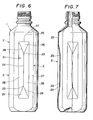
- a bottle-shaped container 1 in Figs. 6 and 7 comprises a body 2 of substantially square-shaped section and made of four panels 3.
- Each panel 3 includes a deforming portion 21.
- a linear bottom line 22 is formed longitudinally in the deforming portion 21.
- Valley lines (bending lines) 24 are formed in V shape or inverted V shape from vertexes 23 at both ends of the bottom line 22.
- the bottom line 22 is formed by inwardly recessing the outer surface 25 of the body 2.
- Oblique walls 26 are formed in inclined portions between the outer sheaths 27 of the deforming portion 21 and the valley lines (bending lines) 24, and the oblique walls 28 are formed in inclined portions formed between the sheaths 27 of the deforming portion 21 and the valley lines (bending lines) 24, and the bottom line 22.
- the deforming portion 21 is formed of the oblique walls 26, 26, and the oblique walls 28, 28.
- the bottom line 21 and the valley lines (bending lines) 24 are formed inwardly into the interior of the container as described above largely different from the conventional panel.
- the deformations against the pressure appled to the deforming portion 21 and the deformations particularly due to the reduced pressure in the container can be smoothly and efficiently performed.
- the deforming portion 21 is externally protruded or formed flatly. Thus, it is necessary to inwardly deform inversely the deforming portion 21 or to deform similarly to the inward deformation when reduced pressure occurs in the container 1.
- the deformation is failed, thus causing the deforming portion to be partly largely deformed or the portion except the deforming portion 21 to be unpreferably deformed to lose the external appearance of the container.
- this embodiment can eliminate the disadvantages of the conventional panel 3.
- the body shape of the bottle-shaped container in Figs. 6 and 7 is of substantially square shape.
- the present invention is not limited to the particular embodiment, and is not used only for the container of rectangular shape, but may be formed in the bottle-shaped container of polygonal and circular cross-sectional shape, as shown in Fig. 1.
- the ratio of the length of the bottom line 22 with respect to the deforming portion 21 is not limited. In the embodiment in Figs. 6 and 7, the length of the bottom line 22 is set to approx. 1/1.7 of the longitudinal length of the deforming portion 21, and disposed at the center of the deforming portion 21. The lengths of the valley lies (bending lines) 24 are determined according to the length of the bottom line 22.
- a deforming portion 21 is surrounded by a recessed groove 41.
- the groove 41 strengthens the rigidity of the body 2 of the bottle-shaped container 1.
- the groove 41 strengthens the rigidity of the body 2 to eliminate the deformation of the body 2 due to the pressure change in the container, thus sufficiently performing the function of the deforming portion 21.
- the shape of the deforming portion 21 formed by surrounding it with the groove 41 is not limited to the rectangular shape, but may be formed in square, polygonal, circular or elliptical to be adapted for the shape of the body 2 of the container and other conditions.
- the sizes and the forming positions of the groove 2 with the deforming portion 21 are not limited. In this fourth embodiment, it is largely formed at the center of the body 2 of the container 1 to provide large reduced pressure in the container 1.
- Grooves 42 are formed above or below the panel 3 for the similar purpose to that of the groove 41.
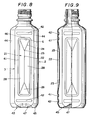
- the embodiment of the bottle-shaped container 1 in Figs. 8 and 10 comprises a body 2 of substantially square sectional shape and a bottom wall 43.
- the body 2 is formed of four panels 3, and edges 44 formed between the panels 3.
- the sectional shape of the bottom surface 45 of the peripheral end of the bottom wall 43 is polygonal shape of integer number times of the number of the side surfaces 46 of the body 2.
- the sectional shape of the bottom surface 45 of the bottom wall 43 is formed to be polygonal shape of the integer number times of the number of the side surfaces 46 of the body 2 (e.g., twice or four times of the number of the side surfaces 46 of the body 2), thereby approaching the sectional shape of the bottom surface 45 to circular shape.
- the orientation of the bottom wall 43 becomes unform, so that no permanent deformation (distortion) feasibly produced due to the irregular remaining stress at the time of heat setting or after completing the bottle-shaped container occurs.
- the bottle-shaped container 1 in Figs. 8 to 10 comprises a body 2 of square-sectional shape and four side surfaces 46, and four edges 44 between the side surfaces.
- the edges 44 are set in width to approx. 1/3 of the width of the edge 44.
- the present invention is not limited to the square shape, but may comprise all polygonal shapes, sch as hexagonal, octagonal shapes, etc.
- A is the width of the edge 44
- B is the length of one side of the polygon of the bottom surface 45.
- the bottom surface 45 is formed in a polygonal shape of the integer number times of the number of the side surfaces 46 of the body 2. This is preferably 2 x times as large as the number of the sides 46 of the body 2, where x is integer number to form the bottle-shaped container 1.
- the center of the bottom wall 43 of the container 1 is inversely bent inwardly of the container 1, and reinforcing ribs 47 are formed at the inversely bent portions. Therefore, the orientation of the bottom wall 43 is increased, and the bottom wall 43 of the container is strengthened by utilizing the properties of the synthetic resin, such as polyethylene terephthalate resin, etc. to increase the mechanical strength and the heat resistance by orienting.
- the number and the shape of the reinforcing ribs 47 are not particularly limited, but suitably selected to perform the objects of providing sufficient mechanical strength and the heat resistance of the bottom wall 43.
- the pressure resistance bottle-shape container according to the present invention is constructed as described above, the deformations of the panels are suppressed when the pressure in the bottle-shaped container is increased, and the panels are smoothly, uniformly and reliably recessed to be deformed when the pressure in the container is reduced. Since the bending lines are formed on the panels, the dimensional stability of the flat panels can be enhance at the time of heat setting the container. Further, when removing the bottle-shaped container from the metal mold after blow-molding the container, no deformation occurs at the panels.
- the surfaces of the body of the container is formed in a polygonal shape of the integer number times of the number of the side surfaces of the body in the cross sectional shape of the bottom of the container as the peripheral end of the bottom wall, orientations of the bottom walls are uniformized, resulting in no permanent deformation occurring at the time of heat setting or completing the container. Further, excellent external appearance of the bottle-shaped container may be provided by the features of the invention described heretofore.
Landscapes
- Engineering & Computer Science (AREA)
- Mechanical Engineering (AREA)
- Ceramic Engineering (AREA)
- Containers Having Bodies Formed In One Piece (AREA)
Priority Applications (1)
| Application Number | Priority Date | Filing Date | Title |
|---|---|---|---|
| EP92105276A EP0506065B1 (de) | 1987-02-17 | 1988-02-16 | Druckfester flaschenartiger Behälter |
Applications Claiming Priority (4)
| Application Number | Priority Date | Filing Date | Title |
|---|---|---|---|
| JP34008/87 | 1987-02-17 | ||
| JP3400887A JP2693153B2 (ja) | 1987-02-17 | 1987-02-17 | 壜体底壁構造 |
| JP3400787A JP2590084B2 (ja) | 1987-02-17 | 1987-02-17 | 壜体パネル壁 |
| JP34007/87 | 1987-02-17 |
Related Child Applications (1)
| Application Number | Title | Priority Date | Filing Date |
|---|---|---|---|
| EP92105276.7 Division-Into | 1988-02-16 |
Publications (3)
| Publication Number | Publication Date |
|---|---|
| EP0279628A2 true EP0279628A2 (de) | 1988-08-24 |
| EP0279628A3 EP0279628A3 (en) | 1989-03-15 |
| EP0279628B1 EP0279628B1 (de) | 1993-05-05 |
Family
ID=26372792
Family Applications (2)
| Application Number | Title | Priority Date | Filing Date |
|---|---|---|---|
| EP88301276A Expired - Lifetime EP0279628B1 (de) | 1987-02-17 | 1988-02-16 | Druckfester flaschenartiger Behälter |
| EP92105276A Expired - Lifetime EP0506065B1 (de) | 1987-02-17 | 1988-02-16 | Druckfester flaschenartiger Behälter |
Family Applications After (1)
| Application Number | Title | Priority Date | Filing Date |
|---|---|---|---|
| EP92105276A Expired - Lifetime EP0506065B1 (de) | 1987-02-17 | 1988-02-16 | Druckfester flaschenartiger Behälter |
Country Status (5)
| Country | Link |
|---|---|
| US (1) | US5064081A (de) |
| EP (2) | EP0279628B1 (de) |
| AU (1) | AU613601B2 (de) |
| CA (1) | CA1312559C (de) |
| DE (2) | DE3880708T2 (de) |
Cited By (7)
| Publication number | Priority date | Publication date | Assignee | Title |
|---|---|---|---|---|
| EP0425124A1 (de) * | 1989-10-24 | 1991-05-02 | CarnaudMetalbox plc | Behälter |
| EP0448007A1 (de) * | 1990-03-22 | 1991-09-25 | SO.GE.A.M. S.p.A. SOCIETA' GESTIONE ACQUE MINERALI | Kunststoffflasche, insbesondere für Getränke |
| WO1996013436A1 (en) * | 1994-10-28 | 1996-05-09 | Continental Pet Technologies, Inc. | Hot-fillable plastic container with tall and slender panel section |
| USD538660S1 (en) | 2005-01-31 | 2007-03-20 | Ball Corporation | Container |
| AU2004205217B2 (en) * | 1999-02-25 | 2008-07-31 | David Murray Melrose | A container having pressure responsive panels |
| EP2248728A4 (de) * | 2008-01-31 | 2011-03-16 | Yoshino Kogyosho Co Ltd | Aus kunstharz hergestellter flaschenkörper |
| CN112041234A (zh) * | 2018-05-28 | 2020-12-04 | 京洛株式会社 | 容器 |
Families Citing this family (94)
| Publication number | Priority date | Publication date | Assignee | Title |
|---|---|---|---|---|
| JPH0644806Y2 (ja) * | 1989-07-10 | 1994-11-16 | 株式会社吉野工業所 | 合成樹脂製壜体 |
| AU647375B2 (en) * | 1989-09-29 | 1994-03-24 | Yoshino Kogyosho Co., Ltd. | Biaxially stretched blow molded bottle |
| CN1022900C (zh) * | 1989-10-07 | 1993-12-01 | 株式会社吉野工业所 | 合成树脂制延伸成型瓶体 |
| US4993566A (en) * | 1989-12-19 | 1991-02-19 | Hoover Universal, Inc. | Spiral container base structure for hot fill pet container |
| US5178289A (en) * | 1992-02-26 | 1993-01-12 | Continental Pet Technologies, Inc. | Panel design for a hot-fillable container |
| US5337909A (en) * | 1993-02-12 | 1994-08-16 | Hoover Universal, Inc. | Hot fill plastic container having a radial reinforcement rib |
| USD352245S (en) | 1993-02-18 | 1994-11-08 | Continental Pet Technologies, Inc. | Vacuum panel container |
| US5341946A (en) * | 1993-03-26 | 1994-08-30 | Hoover Universal, Inc. | Hot fill plastic container having reinforced pressure absorption panels |
| US5449089A (en) * | 1994-02-02 | 1995-09-12 | Williams Industries, Inc. | Bell fountain cup |
| US5908128A (en) * | 1995-07-17 | 1999-06-01 | Continental Pet Technologies, Inc. | Pasteurizable plastic container |
| USD445033S1 (en) | 1995-07-27 | 2001-07-17 | Stokely-Van Camp, Inc. | Bottle |
| WO1997034808A1 (en) * | 1996-03-19 | 1997-09-25 | Graham Packaging Corporation | Blow-molded container having label mount regions separated by peripherally spaced ribs |
| USD419882S (en) * | 1996-04-19 | 2000-02-01 | Snapple Beverage Corporation | Bottle |
| USD420592S (en) * | 1996-04-19 | 2000-02-15 | Snapple Beverage Corporation | Bottle |
| USD397614S (en) | 1996-04-19 | 1998-09-01 | Snapple Beverage Corporation | Bottle |
| USD411453S (en) | 1996-04-19 | 1999-06-22 | Snapple Beverage Corporation | Bottle |
| USD393802S (en) | 1997-01-02 | 1998-04-28 | Continental Pet Technologies, Inc. | Container with waist ribs |
| USD396810S (en) | 1997-04-29 | 1998-08-11 | Owens-Brockway Plastic Products Inc. | Plastic container |
| US5887739A (en) * | 1997-10-03 | 1999-03-30 | Graham Packaging Company, L.P. | Ovalization and crush resistant container |
| USD426460S (en) * | 1997-10-21 | 2000-06-13 | Stokely-Van Camp, Inc. | Bottle |
| USD433322S (en) * | 1997-10-21 | 2000-11-07 | Stokely-Van Camp, Inc. | Bottle |
| USD435453S (en) * | 1997-10-28 | 2000-12-26 | Stokely-Van Camp, Inc. | Bottle |
| US5971184A (en) * | 1997-10-28 | 1999-10-26 | Continental Pet Technologies, Inc. | Hot-fillable plastic container with grippable body |
| USD437555S1 (en) | 1997-10-28 | 2001-02-13 | Stokely-Van Camp, Inc. | Bottle |
| USD441659S1 (en) | 1997-10-28 | 2001-05-08 | Stokely-Van Camp, Inc. | Bottle |
| USD436043S1 (en) | 1997-10-28 | 2001-01-09 | Stokely-Van Camp, Inc. | Bottle |
| USD436042S1 (en) | 1997-10-28 | 2001-01-09 | Stokely-Van Camp, Inc. | Bottle |
| USD442492S1 (en) | 1998-02-09 | 2001-05-22 | Stokely-Van Camp, Inc. | Bottle |
| USD457065S1 (en) | 1998-04-02 | 2002-05-14 | Stokely-Van Camp, Inc. | Bottle |
| USD630515S1 (en) | 1998-10-29 | 2011-01-11 | Stokely-Van Camp, Inc. | Bottle |
| USD431465S (en) * | 1998-11-20 | 2000-10-03 | Crown Cork & Seal Technologies Corporation | Bottle with integrated grip portion |
| USD420587S (en) * | 1998-11-20 | 2000-02-15 | Crown Cork & Seal Technologies Corporation | Bottle with integrated grip portion |
| US6164474A (en) * | 1998-11-20 | 2000-12-26 | Crown Cork & Seal Technologies Corporation | Bottle with integrated grip portion |
| USD422915S (en) * | 1998-12-11 | 2000-04-18 | Bomatic, Inc. | Milk bottle |
| US6158620A (en) * | 1999-02-11 | 2000-12-12 | Chester Labs, Inc. | Collapsible container |
| US7137520B1 (en) | 1999-02-25 | 2006-11-21 | David Murray Melrose | Container having pressure responsive panels |
| USD416198S (en) | 1999-03-01 | 1999-11-09 | Snapple Beverage Corp. | Bottle |
| USD438456S1 (en) | 1999-03-26 | 2001-03-06 | Stokely-Van Camp, Inc. | Bottle |
| USD438455S1 (en) | 1999-03-26 | 2001-03-06 | Stokely-Van Camp, Inc. | Bottle |
| USD454500S1 (en) | 1999-03-26 | 2002-03-19 | Stokely-Van Camp, Inc. | Bottle |
| USD441641S1 (en) | 1999-03-26 | 2001-05-08 | Stokely-Van Camp, Inc. | Bottle |
| USD439167S1 (en) | 1999-03-26 | 2001-03-20 | Stokely-Van Camp, Inc. | Bottle |
| USD442474S1 (en) | 1999-03-26 | 2001-05-22 | Stokely-Van Camp, Inc. | Bottle |
| USD440158S1 (en) | 1999-03-26 | 2001-04-10 | Stokely-Van Camp, Inc. | Bottle |
| USD446126S1 (en) | 1999-03-26 | 2001-08-07 | Stokely-Van Camp, Inc. | Bottle |
| USD441294S1 (en) | 1999-03-26 | 2001-05-01 | Stokely-Van Camp, Inc. | Bottle |
| USD440157S1 (en) | 1999-03-26 | 2001-04-10 | Stokely-Van Camp, Inc. | Bottle |
| CN1091060C (zh) * | 1999-07-13 | 2002-09-18 | 深圳景田实业有限公司 | 饮用水塑料包装瓶 |
| USD457055S1 (en) | 2000-01-10 | 2002-05-14 | Stokely-Van Camp, Inc. | Bottle |
| USD448672S1 (en) | 2000-02-11 | 2001-10-02 | Crown Cork & Seal Technologies Corporation | Container |
| USD448303S1 (en) | 2000-02-11 | 2001-09-25 | Crown Cork & Seal Technologies Corporation | Container |
| USD448304S1 (en) | 2000-07-21 | 2001-09-25 | Crown Cork & Seal Technologies Corporation | Container |
| USD448302S1 (en) | 2000-07-21 | 2001-09-25 | Crown Cork & Seal Technologies Corporation | Container |
| TWI228476B (en) * | 2000-08-31 | 2005-03-01 | Co2 Pac Ltd | Semi-rigid collapsible container |
| US6409035B1 (en) | 2000-11-28 | 2002-06-25 | Plastipak Packaging, Inc. | Hollow plastic bottles |
| CA2429834C (en) * | 2000-12-20 | 2008-10-07 | Yoshino Kogyosho Co., Ltd. | A container made of synthethic resin |
| CA2368491C (en) * | 2001-01-22 | 2008-03-18 | Ocean Spray Cranberries, Inc. | Container with integrated grip portions |
| USD459234S1 (en) | 2001-02-13 | 2002-06-25 | Ocean Spray Cranberries, Inc. | Bottle |
| USD462271S1 (en) | 2001-02-21 | 2002-09-03 | Ocean Spray Cranberries, Inc. | Bottle |
| JP2002326619A (ja) * | 2001-04-27 | 2002-11-12 | Yoshino Kogyosho Co Ltd | ブローボトル |
| WO2002098752A1 (en) | 2001-06-04 | 2002-12-12 | Crown Cork & Seal Technologies Corporation | Hot-fillable container with grip |
| USD486071S1 (en) | 2001-09-25 | 2004-02-03 | Constar International Inc. | Beverage bottle with hand grip |
| USD469360S1 (en) | 2001-12-20 | 2003-01-28 | Ball Corporation | Plastic bottle |
| US20030161980A1 (en) * | 2002-02-27 | 2003-08-28 | Nelson Brent S. | Plastic container |
| USD488722S1 (en) | 2002-05-09 | 2004-04-20 | Stokely-Van Camp, Inc. | Bottle |
| USD488723S1 (en) | 2002-05-09 | 2004-04-20 | Stokely-Van Camp, Inc. | Bottle portion |
| USD482287S1 (en) | 2002-05-10 | 2003-11-18 | Constar International, Inc. | Grippable bottle |
| EP1549551A4 (de) * | 2002-09-23 | 2005-12-14 | Graham Packaging Co | Kunststoffkaraffe |
| CA2499478A1 (en) * | 2002-09-23 | 2004-04-01 | Graham Packaging Company L.P. | Plastic carafe |
| US6997336B2 (en) * | 2002-09-23 | 2006-02-14 | Graham Packaging Company, L.P. | Plastic cafare |
| US9969517B2 (en) | 2002-09-30 | 2018-05-15 | Co2Pac Limited | Systems and methods for handling plastic containers having a deep-set invertible base |
| USD485493S1 (en) | 2002-12-03 | 2004-01-20 | Nestle Waters North America, Inc. | Beverage container |
| US7172087B1 (en) | 2003-09-17 | 2007-02-06 | Graham Packaging Company, Lp | Squeezable container and method of manufacture |
| USD496584S1 (en) * | 2003-10-15 | 2004-09-28 | Plastipak Packaging, Inc. | Handle for container |
| JP4864316B2 (ja) * | 2003-11-26 | 2012-02-01 | 株式会社吉野工業所 | 合成樹脂製耐熱ボトル型容器 |
| US7350657B2 (en) * | 2004-03-25 | 2008-04-01 | Mott's Llp | Grip for beverage container |
| US7823737B2 (en) * | 2005-02-02 | 2010-11-02 | Graham Packaging Company, L.P. | Plastic container with substantially flat panels |
| US8017065B2 (en) | 2006-04-07 | 2011-09-13 | Graham Packaging Company L.P. | System and method for forming a container having a grip region |
| US20070012648A1 (en) * | 2005-07-14 | 2007-01-18 | Ball Corporation | Container base with releaved corner geometry |
| US7455189B2 (en) * | 2005-08-22 | 2008-11-25 | Amcor Limited | Rectangular hot-filled container |
| US7857157B2 (en) * | 2006-01-25 | 2010-12-28 | Amcor Limited | Container having segmented bumper rib |
| US7861876B2 (en) * | 2006-09-22 | 2011-01-04 | Ball Corporation | Bottle with intruding margin vacuum responsive panels |
| US7699183B2 (en) * | 2007-04-09 | 2010-04-20 | The Coca-Cola Company | Square bottle manufactured from synthetic resin |
| US8113369B2 (en) * | 2008-12-22 | 2012-02-14 | Amcor Limited | Container |
| USD657665S1 (en) * | 2010-04-30 | 2012-04-17 | Consolidated Container Company Lp | Stackable container |
| US8556097B2 (en) * | 2011-02-16 | 2013-10-15 | Amcor Limited | Container having vacuum panel with balanced vacuum and pressure response |
| CN103635402B (zh) * | 2011-06-28 | 2017-03-22 | Abc集团公司 | 用于冻结情况的膨胀表面轮廓 |
| US8919587B2 (en) * | 2011-10-03 | 2014-12-30 | Graham Packaging Company, L.P. | Plastic container with angular vacuum panel and method of same |
| US9849622B2 (en) * | 2012-02-10 | 2017-12-26 | Discma Ag | Method of blowing, filling and capping containers |
| CN104093638B (zh) | 2012-02-29 | 2016-03-23 | 株式会社吉野工业所 | 瓶 |
| USD782910S1 (en) | 2015-08-28 | 2017-04-04 | Pepsico, Inc. | Bottle |
| US12129072B2 (en) * | 2021-11-30 | 2024-10-29 | Pepsico, Inc. | Flexible base for aseptic-fill bottles |
| JP1764983S (ja) * | 2023-10-13 | 2024-03-06 | 包装用容器 | |
| JP1764950S (ja) * | 2023-10-13 | 2024-03-06 | 包装用容器 |
Family Cites Families (33)
| Publication number | Priority date | Publication date | Assignee | Title |
|---|---|---|---|---|
| DE293908C (de) * | ||||
| DE1883765U (de) * | 1963-09-02 | 1963-11-28 | Bayer Ag | Behaelter, insbesondere treibstoffbehaelter. |
| FR1397037A (fr) * | 1964-05-26 | 1965-04-23 | Unipol S A Soc | Capacité constituant un conditionnement pour produits fluides |
| FR1449600A (fr) * | 1964-09-14 | 1966-05-06 | Fr Des Laboratoires Labaz Soc | Perfectionnements aux flacons en matière souple, notamment pour produits médicamenteux |
| US3225950A (en) * | 1965-03-22 | 1965-12-28 | Grace W R & Co | Plastic bottle |
| US3397724A (en) * | 1966-06-03 | 1968-08-20 | Phillips Petroleum Co | Thin-walled container and method of making the same |
| NL154462B (nl) * | 1967-09-15 | 1977-09-15 | Mauser Kg | In een blaasproces vervaardigde kunststofbus. |
| US3499567A (en) * | 1967-10-09 | 1970-03-10 | Shell Oil Co | Neck structure for thin-walled plastic containers |
| US3558001A (en) * | 1969-08-07 | 1971-01-26 | Exxon Research Engineering Co | Thermoplastic container |
| US3708082A (en) * | 1971-03-29 | 1973-01-02 | Hoover Ball & Bearing Co | Plastic container |
| SE403342B (sv) * | 1972-12-08 | 1978-08-14 | Rit Rech Ind Therapeut | Hopfellbar halvstel plastflaska |
| US3931074A (en) * | 1974-03-14 | 1976-01-06 | Monsanto Company | Modifiers for high nitrile polymers |
| JPS5430654A (en) * | 1977-08-08 | 1979-03-07 | Keifuku Kin | Method of automatically removing settled sludge through side wall surface of conduit fixed to bottom |
| US4298045A (en) * | 1978-04-17 | 1981-11-03 | Automatic Liquid Packaging, Inc. | Dispensing container with plural removable closure means unitary therewith |
| GB2024087B (en) * | 1978-06-29 | 1982-08-25 | Yoshino Kogyosho Co Ltd | Blow moulding polyester container |
| LU81256A1 (fr) * | 1979-05-15 | 1980-12-16 | Oreal | Composition cosmetique capillaire notamment pour le lavage et/ou le demelage des cheveux,a base d'un extrait de plantes contenant des saponosides |
| US4749092A (en) * | 1979-08-08 | 1988-06-07 | Yoshino Kogyosho Co, Ltd. | Saturated polyester resin bottle |
| USD261864S (en) | 1979-09-19 | 1981-11-17 | Sunbeam Plastics Corporation | Bottle |
| FI69803C (fi) * | 1979-09-24 | 1986-05-26 | Unilever Nv | Kaerl |
| US4372455A (en) * | 1980-01-18 | 1983-02-08 | National Can Corporation | Thin walled plastic container construction |
| US4318882A (en) * | 1980-02-20 | 1982-03-09 | Monsanto Company | Method for producing a collapse resistant polyester container for hot fill applications |
| US4497855A (en) * | 1980-02-20 | 1985-02-05 | Monsanto Company | Collapse resistant polyester container for hot fill applications |
| JPS57126310A (en) * | 1981-01-26 | 1982-08-06 | Daifuku Co Ltd | Gravity roller conveyor |
| US4387816A (en) * | 1982-01-18 | 1983-06-14 | Owens-Illinois, Inc. | Collapse resistant container |
| US4535902A (en) * | 1982-04-01 | 1985-08-20 | Continental Packaging Company, Inc. | Intermediate article of manufacture for a plastic container |
| JPS6076613U (ja) * | 1983-10-31 | 1985-05-29 | 日精エー・エス・ビー機械株式会社 | 耐熱性合成樹脂びん |
| US4589560A (en) * | 1984-09-25 | 1986-05-20 | Mckesson Corporation | Bottle and crate for containing liquids |
| USD287934S (en) | 1984-09-25 | 1987-01-27 | Mckesson Corporation | Plastic bottle for liquids |
| CA1282018C (en) * | 1985-04-17 | 1991-03-26 | Akiho Ota | Biaxial-orientation blow-molded bottle-shaped container |
| US4805788A (en) * | 1985-07-30 | 1989-02-21 | Yoshino Kogyosho Co., Ltd. | Container having collapse panels with longitudinally extending ribs |
| GB2188272B (en) * | 1986-02-28 | 1990-10-10 | Toyo Seikan Kaisha Ltd | A process for preparation of a biaxially drawn polyester vessel having resistance to heat distortion and gas barrier properties. |
| US4802295A (en) * | 1987-04-28 | 1989-02-07 | Plastipak Packaging, Inc. | Blow molded polyethylene terephthalate container having IML textured label wall and method for making same |
| AU589406B2 (en) * | 1987-09-02 | 1989-10-12 | Yoshino Kogyosho Co., Ltd. | Neck structure of synthetic resin bottle-shaped container |
-
1988
- 1988-02-16 DE DE8888301276T patent/DE3880708T2/de not_active Expired - Fee Related
- 1988-02-16 CA CA000559015A patent/CA1312559C/en not_active Expired - Lifetime
- 1988-02-16 EP EP88301276A patent/EP0279628B1/de not_active Expired - Lifetime
- 1988-02-16 EP EP92105276A patent/EP0506065B1/de not_active Expired - Lifetime
- 1988-02-16 DE DE3852894T patent/DE3852894T2/de not_active Expired - Fee Related
- 1988-02-17 AU AU11913/88A patent/AU613601B2/en not_active Ceased
-
1991
- 1991-03-28 US US07/679,143 patent/US5064081A/en not_active Expired - Lifetime
Cited By (15)
| Publication number | Priority date | Publication date | Assignee | Title |
|---|---|---|---|---|
| EP0425124A1 (de) * | 1989-10-24 | 1991-05-02 | CarnaudMetalbox plc | Behälter |
| WO1991006482A1 (en) * | 1989-10-24 | 1991-05-16 | Cmb Foodcan Plc | Containers |
| TR24621A (tr) * | 1989-10-24 | 1992-01-01 | Cmb Foodcan Plc | Metal teneke kutu goevdeleri |
| AP180A (en) * | 1989-10-24 | 1992-05-12 | Metal Box Plc | Containers. |
| EP0448007A1 (de) * | 1990-03-22 | 1991-09-25 | SO.GE.A.M. S.p.A. SOCIETA' GESTIONE ACQUE MINERALI | Kunststoffflasche, insbesondere für Getränke |
| US5704503A (en) * | 1994-10-28 | 1998-01-06 | Continental Pet Technologies, Inc. | Hot-fillable plastic container with tall and slender panel section |
| WO1996013436A1 (en) * | 1994-10-28 | 1996-05-09 | Continental Pet Technologies, Inc. | Hot-fillable plastic container with tall and slender panel section |
| AU2004205217B2 (en) * | 1999-02-25 | 2008-07-31 | David Murray Melrose | A container having pressure responsive panels |
| AU2004205217C1 (en) * | 1999-02-25 | 2009-01-08 | David Murray Melrose | A container having pressure responsive panels |
| USD538660S1 (en) | 2005-01-31 | 2007-03-20 | Ball Corporation | Container |
| EP2248728A4 (de) * | 2008-01-31 | 2011-03-16 | Yoshino Kogyosho Co Ltd | Aus kunstharz hergestellter flaschenkörper |
| AU2009208458B2 (en) * | 2008-01-31 | 2013-05-02 | Yoshino Kogyosho Co., Ltd. | Synthetic resin bottle |
| KR101538178B1 (ko) * | 2008-01-31 | 2015-07-20 | 가부시키가이샤 요시노 고교쇼 | 합성수지제 병체 |
| CN112041234A (zh) * | 2018-05-28 | 2020-12-04 | 京洛株式会社 | 容器 |
| CN112041234B (zh) * | 2018-05-28 | 2023-06-02 | 京洛株式会社 | 容器 |
Also Published As
| Publication number | Publication date |
|---|---|
| EP0506065A1 (de) | 1992-09-30 |
| EP0279628B1 (de) | 1993-05-05 |
| DE3852894D1 (de) | 1995-03-09 |
| CA1312559C (en) | 1993-01-12 |
| US5064081A (en) | 1991-11-12 |
| DE3852894T2 (de) | 1995-05-24 |
| DE3880708D1 (de) | 1993-06-09 |
| DE3880708T2 (de) | 1993-08-19 |
| AU1191388A (en) | 1988-08-18 |
| EP0506065B1 (de) | 1995-01-25 |
| AU613601B2 (en) | 1991-08-08 |
| EP0279628A3 (en) | 1989-03-15 |
Similar Documents
| Publication | Publication Date | Title |
|---|---|---|
| US4877141A (en) | Pressure resistant bottle-shaped container | |
| EP0279628A2 (de) | Druckfester flaschenartiger Behälter | |
| US5199588A (en) | Biaxially blow-molded bottle-shaped container having pressure responsive walls | |
| US6929138B2 (en) | Hot-fillable multi-sided blow-molded container | |
| DE69034008T2 (de) | Flaschenförmiger Behälter aus Kunststoff | |
| US8181805B2 (en) | Hot fill container | |
| KR100730334B1 (ko) | 보형성이 우수한 합성 수지제 용기 | |
| AU2009208458B2 (en) | Synthetic resin bottle | |
| US7874442B2 (en) | Hot-fill plastic container with ribs and grip | |
| US20110108515A1 (en) | Plastic container with improved sidewall configuration | |
| JPH0751460Y2 (ja) | 角形プラスチックボトル | |
| CN100569594C (zh) | 保形性佳的合成树脂容器 | |
| JP2693153B2 (ja) | 壜体底壁構造 | |
| JP4144765B2 (ja) | 合成樹脂製壜体 | |
| JP4393731B2 (ja) | 保形性に優れた合成樹脂製容器 | |
| JPH0740953A (ja) | 合成樹脂製壜体 | |
| JP5966358B2 (ja) | 合成樹脂製容器 | |
| JPH1159646A (ja) | 合成樹脂製ボトル | |
| JP3982654B2 (ja) | 合成樹脂製補強パネルおよびこの合成樹脂製補強パネルを用いた合成樹脂製壜体 | |
| JPH08310521A (ja) | 合成樹脂製壜体 | |
| JPH11255226A (ja) | 合成樹脂製補強パネルおよびこの合成樹脂製補強パネルを用いた合成樹脂製壜体 | |
| JPH07102856B2 (ja) | 壜体の変形用パネル壁 | |
| JPH11255229A (ja) | 合成樹脂製補強部材およびこの合成樹脂製補強部材を用いた合成樹脂製壜体 | |
| JP2511931Y2 (ja) | 補強リブ付きプラスチックボトル | |
| WO2019171799A1 (ja) | プラスチックボトル |
Legal Events
| Date | Code | Title | Description |
|---|---|---|---|
| PUAI | Public reference made under article 153(3) epc to a published international application that has entered the european phase |
Free format text: ORIGINAL CODE: 0009012 |
|
| AK | Designated contracting states |
Kind code of ref document: A2 Designated state(s): CH DE FR GB IT LI NL |
|
| PUAL | Search report despatched |
Free format text: ORIGINAL CODE: 0009013 |
|
| AK | Designated contracting states |
Kind code of ref document: A3 Designated state(s): CH DE FR GB IT LI NL |
|
| 17P | Request for examination filed |
Effective date: 19890803 |
|
| 17Q | First examination report despatched |
Effective date: 19910418 |
|
| GRAA | (expected) grant |
Free format text: ORIGINAL CODE: 0009210 |
|
| AK | Designated contracting states |
Kind code of ref document: B1 Designated state(s): CH DE FR GB IT LI NL |
|
| ITF | It: translation for a ep patent filed | ||
| XX | Miscellaneous (additional remarks) |
Free format text: TEILANMELDUNG 92105276.7 EINGEREICHT AM 16/02/88. |
|
| REF | Corresponds to: |
Ref document number: 3880708 Country of ref document: DE Date of ref document: 19930609 |
|
| ET | Fr: translation filed | ||
| PLBE | No opposition filed within time limit |
Free format text: ORIGINAL CODE: 0009261 |
|
| STAA | Information on the status of an ep patent application or granted ep patent |
Free format text: STATUS: NO OPPOSITION FILED WITHIN TIME LIMIT |
|
| 26N | No opposition filed | ||
| PGFP | Annual fee paid to national office [announced via postgrant information from national office to epo] |
Ref country code: NL Payment date: 20010228 Year of fee payment: 14 |
|
| PGFP | Annual fee paid to national office [announced via postgrant information from national office to epo] |
Ref country code: CH Payment date: 20010508 Year of fee payment: 14 |
|
| REG | Reference to a national code |
Ref country code: GB Ref legal event code: IF02 |
|
| PG25 | Lapsed in a contracting state [announced via postgrant information from national office to epo] |
Ref country code: CH Free format text: LAPSE BECAUSE OF NON-PAYMENT OF DUE FEES Effective date: 20020228 Ref country code: LI Free format text: LAPSE BECAUSE OF NON-PAYMENT OF DUE FEES Effective date: 20020228 |
|
| PG25 | Lapsed in a contracting state [announced via postgrant information from national office to epo] |
Ref country code: NL Free format text: LAPSE BECAUSE OF NON-PAYMENT OF DUE FEES Effective date: 20020901 |
|
| REG | Reference to a national code |
Ref country code: CH Ref legal event code: PL |
|
| NLV4 | Nl: lapsed or anulled due to non-payment of the annual fee |
Effective date: 20020901 |
|
| PGFP | Annual fee paid to national office [announced via postgrant information from national office to epo] |
Ref country code: FR Payment date: 20050208 Year of fee payment: 18 |
|
| PG25 | Lapsed in a contracting state [announced via postgrant information from national office to epo] |
Ref country code: IT Free format text: LAPSE BECAUSE OF NON-PAYMENT OF DUE FEES;WARNING: LAPSES OF ITALIAN PATENTS WITH EFFECTIVE DATE BEFORE 2007 MAY HAVE OCCURRED AT ANY TIME BEFORE 2007. THE CORRECT EFFECTIVE DATE MAY BE DIFFERENT FROM THE ONE RECORDED. Effective date: 20050216 |
|
| PGFP | Annual fee paid to national office [announced via postgrant information from national office to epo] |
Ref country code: DE Payment date: 20060209 Year of fee payment: 19 |
|
| PGFP | Annual fee paid to national office [announced via postgrant information from national office to epo] |
Ref country code: GB Payment date: 20060215 Year of fee payment: 19 |
|
| GBPC | Gb: european patent ceased through non-payment of renewal fee |
Effective date: 20070216 |
|
| REG | Reference to a national code |
Ref country code: FR Ref legal event code: ST Effective date: 20071030 |
|
| PG25 | Lapsed in a contracting state [announced via postgrant information from national office to epo] |
Ref country code: DE Free format text: LAPSE BECAUSE OF NON-PAYMENT OF DUE FEES Effective date: 20070901 |
|
| PG25 | Lapsed in a contracting state [announced via postgrant information from national office to epo] |
Ref country code: GB Free format text: LAPSE BECAUSE OF NON-PAYMENT OF DUE FEES Effective date: 20070216 Ref country code: FR Free format text: LAPSE BECAUSE OF NON-PAYMENT OF DUE FEES Effective date: 20070228 |
|
| PG25 | Lapsed in a contracting state [announced via postgrant information from national office to epo] |
Ref country code: FR Free format text: LAPSE BECAUSE OF NON-PAYMENT OF DUE FEES Effective date: 20060228 |