EP0279660B1 - Automatische, vollständige Siloentnahmevorrichtung - Google Patents
Automatische, vollständige Siloentnahmevorrichtung Download PDFInfo
- Publication number
- EP0279660B1 EP0279660B1 EP88301343A EP88301343A EP0279660B1 EP 0279660 B1 EP0279660 B1 EP 0279660B1 EP 88301343 A EP88301343 A EP 88301343A EP 88301343 A EP88301343 A EP 88301343A EP 0279660 B1 EP0279660 B1 EP 0279660B1
- Authority
- EP
- European Patent Office
- Prior art keywords
- impacting head
- hose
- internal gas
- build
- impacting
- Prior art date
- Legal status (The legal status is an assumption and is not a legal conclusion. Google has not performed a legal analysis and makes no representation as to the accuracy of the status listed.)
- Expired - Lifetime
Links
Images

Classifications
-
- B—PERFORMING OPERATIONS; TRANSPORTING
- B65—CONVEYING; PACKING; STORING; HANDLING THIN OR FILAMENTARY MATERIAL
- B65D—CONTAINERS FOR STORAGE OR TRANSPORT OF ARTICLES OR MATERIALS, e.g. BAGS, BARRELS, BOTTLES, BOXES, CANS, CARTONS, CRATES, DRUMS, JARS, TANKS, HOPPERS, FORWARDING CONTAINERS; ACCESSORIES, CLOSURES, OR FITTINGS THEREFOR; PACKAGING ELEMENTS; PACKAGES
- B65D88/00—Large containers
- B65D88/54—Large containers characterised by means facilitating filling or emptying
- B65D88/64—Large containers characterised by means facilitating filling or emptying preventing bridge formation
- B65D88/68—Large containers characterised by means facilitating filling or emptying preventing bridge formation using rotating devices
Definitions
- the present invention is directed to a method and apparatus for automatically removing the build-up of particulate in a storage bin, such as a coal bunker, grain silo, and the like.
- coal bunkers house several thousand tons of coal.
- the dimensions of a typical cylindrical coal bunker are about 70 feet in diameter and over 110 feet (33.5m) high; a typical rectangular coal bunker is 25 by 80 feet by over 50 feet deep (7.6m x 24.3m x over 15.2m).
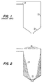
- a typical prior art coal bunker is shown.
- the coal is fed into the bunker by means of a conveyor belt (not shown) positioned near top 21 of the coal bunker.
- the coal is removed from the bunker through conical-shaped hoppers, such as hopper 22, located at the bottom of the bunker. Through use, coal tends to build up along side walls 23 of the bunker, thereby reducing the effective capacity of the bunker.
- coal bunkers are cleaned on a periodic basis as a means of preventive maintenance.
- prior art methods of cleaning the build-up are directed to sending a crew of workmen into the bunker to manually remove the build-up, usually by jack hammer, pick axe, and the like.
- the crew of workmen are typically lowered into the bunker from the top and safety lines are attached to the workmen to help prevent accidents.
- this method is quite dangerous. Should a large portion of build-up break from the wall, and should a workman get caught in the falling debris, the weight of it can drag the workman down, despite the safety lines. It is well known and documented that many lives have been lost throughout the years due to this cleaning process, in spite of safety lines.
- Barger includes a series of inflatable hoses along the side walls of the storage bin which are inflatable to help the particles of soybean meal stuck to the side of the wall to dislodge, eventually exiting the hopper at its bottom.
- the inflatable hoses are rigidly attached near the top and bottom opening of the silo, and attached near the side walls of the conical-shaped hopper with a spring device which allows the hose, when inflated, to move away from the silo wall, creating an incline for the meal to slide down and breaking it up from the sides of the silo.
- the spring device causes the hose to return to the side wall once it is deflated.
- the present invention may be constructed out of any material suitable for the required application.
- brass may be used in environments where it is inherently dangerous for sparks to be created when the head impacts the particulate, such as in a coal bunker.
- steel such as carbon or stainless, may also be used, as well as a plastic composition, wood or the like.
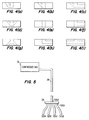
- the preferred embodiment of the cutting tip includes internal gas passageway 35 running throughout the interior of both the elongated arm and the impacting head.
- internal gas passageway 35 running throughout the interior of both the elongated arm and the impacting head.
- any number of such internal gas passageways connected between the end of the elongated arm and any portion of the exterior of the impacting head is available.
- FIG 2 when the present invention is used to clean the coal built-up along the walls of a coal bunker, access to the coal build-up is achieved, in the prefered embodiment, by cutting a plurality of holes 26 in the top of the coal bunker and lowering the cutting tip down to the coal build-up.
- a plurality of cutting tips attached to a common source of compressed air.
- FIG 5 the apparatus for achieving this is shown, and includes source of compressed gas 51 connected to a plurality of cutting tips (not shown) via hoses 52(a)-(d).
- the plurality of hoses are attached to the common source of compressed gas by manifold 53 and hose 54.
- the compressed gas should have a flow rate of at least 500 cubic feet per minute (cfm) (236 l/s), and more preferably a flow rate of at least 750 cfm (354 l/s) when used in the configuration shown in Figure 5.
- cfm cubic feet per minute
- the rate at which cleaning is to be conducted the internal diameters of hoses 54 and 52, as well as the diameter of internal passageway(s) 35 of the cutting tip shown in Figure 3.
Landscapes
- Engineering & Computer Science (AREA)
- Mechanical Engineering (AREA)
- Filling Or Emptying Of Bunkers, Hoppers, And Tanks (AREA)
- Filling Or Discharging Of Gas Storage Vessels (AREA)
- Apparatus For Radiation Diagnosis (AREA)
- Road Repair (AREA)
- Paper (AREA)
- Air Transport Of Granular Materials (AREA)
- Cleaning In General (AREA)
Claims (32)
- Verfahren zur Entfernung von Feststoffanreicherung (24), die an der Innenfläche (23) eines Silos haftet, der im wesentlichen frei Von sich frei bewegenden, diskreten Teilchen des Lagermaterials ist, das folgende Schritte enthält:- das Einhängen von einem länglichen, flexiblen Schlauch in das Innere des Silos, mit dem eine Schlagkopf (31) benachbart zum Ende des Schlauches verbunden ist, der eine Außenfläche zum festen Schlagen der Anreicherung (24) auf der Innenfläche (23) des Silos aufweist und der einen bestimmten Gasdurchlaß aufweist, wobei der eingehängte Schlagkopf (31) die Anreicherung (24) an der Innenfläche (23) des Silos schlagen kann; und- das Fließen von komprimiertem Gas durch den Schlauch und den Schlagkopf (31) bei einem ausreichenden Druck, um den Schlagkopf (31) unregelmäßig zu wirbeln und ihn zum festen Schlagen auf die Anreicherung (24) anzutreiben, wodurch die Anreicherung (24) von der Innenfläche (23) des Silos entfernt wird, wobei das Verfahrendadurch gekennzeichnet
ist, daß der Schlauch frei ohne die Hilfe von Führungen innerhalb des Silos von oben in den Silo gehängt wird und daß der Schlagkopf (31) durch eine Verbindung (32) mit dem Schlauch verbunden ist, die einen langen Arm mit einem ersten Ende aufweist, das mit dem Schlagkopf (31) verbunden ist und einem zweiten Ende, das Kupplungsmittel (36) enthält, um den Schlauch zu befestigen. - Verfahren nach Anspruch 1, wobei das komprimierte Gas mit einem Druck von mindestens 345 kPa (50 psi) durch den Schlagkopf (31) geleitet wird.
- Verfahren nach Anspruch 2, wobei das komprimierte Gas mit einem Druck von mindestens 690 kPa (100 psi) durch den Schlagkopf (31) geleitet wird.
- Verfahren nach Anspruch 3, wobei das komprimierte Gas mit einem Druck von mindestens 1034 kPa (150 psi) durch den Schlagkopf (31) geleitet wird.
- Verfahren nach einem oder mehreren der Ansprüche 1 - 4, wobei das komprimierte Gas mit einem Strom von mindestens 236 l/s (500 cfm) durch den Schlagkopf (31) geleitet wird.
- Verfahren nach Anspruch 5, wobei das komprimierte Gas in einem Strom von mindestens 354 l/s (750 cfm) durch den Schlagkopf (31) geleitet wird.
- Verfahren nach Anspruch 1, wobei eine Vorrichtung verwendet wird, bei der der Schlaggkopf (31) im wesentlichen zylindrisch ist und im wesentlichen einen Durchmesser von 3,5 inches (89 mm) und eine Länge von 1 inch (25,4 mm) aufweist, bei der der lange Arm (32) im wesentlichen zylindrisch ist und im wesentlichen einen Durchmesser von 0,75 inch (19,1 mm) und eine Länge von 4 inches (102 mm) aufweist, wobei Schlagkopf (31) und der lange Arm (32) aus Messing oder rostfreiem Stahl bestehen, wobei der Gasdurchlaß im wesentlichen einen Durchmesser zwischen 0,5 inch (19,1 mm) und 9/16 inch (14,3 mm) aufweist und wobei das komprimierte Gas mit einem Druck von mindestens 150 psi (1034 kPa) und einem Strom von mindestens 750 cfm (354 l/s) durch den Schlagkopf (31) geleitet wird.
- Verfahren nach einem oder mehreren der Ansprüche 1 - 7, wobei das Gas axial durch den Schlagkopf (31) und den Schlauch fließt.
- Verfahren nach einem oder mehreren der Ansprüche 1 - 7, wobei das Gas in einem Winkel zu der Achse des Schlauches an der Stelle der Verbindung mit dem Schlagkopf (31) durch denselben fließt.
- Verfahren nach einem oder mehreren der Ansprüche 1- 7, wobei das Gas durch eine Vielzahl von internen Gasleitungen durch den Schlagkopf (31) fließt.
- Verfahren nach einem oder mehreren der Ansprüche 1 - 10, wobei das komprimierte Gas komprimierte Luft ist.
- Vorrichtung zur automatischen Entfernung von Feststoffanreicherung (24), die an der Innenfläche (23) eines Silos haftet, der im wesentlichen frei von sich frei bewegenden, diskreten Teilchen des Lagermaterials ist, wobei die Vorrichtung folgendes enthält:- mindestens einen flexiblen Schlauch;- einen mit jedem flexiblen Schlauch verbundenen Schlagkopf (31), der eine Außenfläche zum festen Schlagen der Anreicherung (24) auf der Innenfläche (23) und einen ersten internen Gasdurchlaß (35) aufweist, die mindestens eine Öffnung hat, wobei der erste interne Gasdurchlaß (35) in Strömungsverbindung mit dem flexiblen Schlauch steht, um Gas von dem flexiblen Schlauch durch das Innere des Schlagkopfes (31) nach außen zu leiten und aus dem Schlagkopf (31) durch den ersten internen Gasdurchlaß (35);- eine Verbindung (32) um den Schlagkopf (31) mit dem flexiblen Schlauch zu verbinden, wobei die Verbindung (32) mit einem ersten Ende mit dem Schlagkopf (31) und einem zweiten Ende mit dem flexiblen Schlauch verbunden ist;- und eine Quelle (51) für komprimiertes Gas, um komprimiertes Gas zu dem flexiblen Schlauch zu leiten, wobei die Quelle (51) für komprimiertes Gas mit dem flexiblen Schlauch verbunden ist;- wobei der Durchlaß so bemessen ist daß das komprimierte Gas durch den Schlagkopf (31) mit einem ausreichenden Druck fließen kann, um den Schlagkopf (31) unregelmäßig zu wirbeln, und um ihn zum festen Schlagen und Entfernen der Anreicherung (24) von der Innenfläche (23) des Silos anzutreiben, wobei die Vorrichtung fähig ist, Anreicherungen (24) an der Innenfläche (23) des Silos zu entfernen, dadurch gekennzeichnet, daß die Verbindung (32) einen langen Arm enthält, der ein erstes Ende aufweist, das mit dem Schlagkopf (31) verbunden ist sowie ein zweites Ende, das Kupplungsmittel (36) enthält, um den Schlauch anzukoppeln und daß die Vorrichtung keine Führungen innerhalb des Silos für den eingehängten Schlauch und den Schlagkopf enthält.
- Vorrichtung nach Anspruch 12, wobei die Außenfläche des Schlagkopfes (31) im wesentlichen zylindrisch ist und folgendes enthält:- erste und zweite im wesentlichen kreisförmige Flächen, wobei die erste Fläche mit dem ersten Ende der Verbindung (32) verbindbar ist; und- eine dazwischen angeordnete Fläche, die die erste und zweite Fläche miteinander verbindet.
- Vorrichtung nach Anspruch 13, wobei die erste im wesentliche kreisförmige Fläche außerdem einen ersten Bereich der Außenfläche enthält, mit dem der zweite interne Gasdurchlaß (35) verbunden ist.
- Vorrichtung nach Anspruch 14, wobei die im wesentlichen kreisförmige Fläche einen zweiten Bereich der Außenfläche enthält, mit dem ein zweiter interner Gasdurchlaß verbunden ist, wobei das Gas den Schlagkopf (31) auch durch eine Öffnung in dem zweiten internen Gasdurchlaß verläßt.
- Vorrichtung nach Anspruch 15, wobei die zwischenliegend angeordnete Fläche einen zweiten Bereich der Außenfläche enthält, mit dem ein zweiter interne Gasdurchlaß verbunden ist, wobei das Gas den Schlagkopf (31) auch durch eine Öffnung in dem zweiten internen Gasdurchlaß verläßt.
- Vorrichtung nach Anspruch 16, wobei die erste im wesentlichen kreisförmige Fläche einen zweiten Bereich der Außenfläche enthält, mit dem ein zweiter interner Gasdurchlaß verbunden ist, wobei das Gas den Schlagkopf (31) auch durch eine Öffnung in dem zweiten internen Gasdurchlaß verläßt.
- Vorrichtung nach Anspruch 13, wobei die zweite im wesentlichen kreisförmige Fläche einen ersten Bereich der Außenfläche enthält, mit dem der erste interne Gasdurchlaß (35) verbunden ist.
- Vorrichtung nach Anspruch 18, wobei die zweite im wesentlichen kreisförmige Fläche einen zweiten Bereich der Außenfläche enthält, mit dem ein zweiter interner Gasdurchlaß verbunden ist, wobei das Gas den Schlagkopf (31) auch durch eine Öffnung in dem zweiten internen Gasdurchlaß verläßt.
- Vorrichtung nach Anspruch 18, wobei die dazwischen liegende Fläche einen zweiten Bereich der Außenfäche enthält, mit dem ein zweiter interner Gasdurchlaß verbunden ist, wobei das Gas den Schlagkopf (31) auch durch eine Öffnung in dem zweiten internen Gasdurchlaß verläßt.
- Vorrichtung nach Anspruch 13, wobei die dazwischen liegende Fläche einen ersten Bereich der Außenfläche enthält, mit den der erste interne Gasdurchlaß (35) verbunden ist.
- Vorrichtung nach Anspruch 21, wobei die dazwischen liegende Fläche außerdem einen zweiten Bereich der Außenfläche enthält, mit dem ein zweiter interner Gasdurchlaß verbunden ist, wobei das Gas den Schlagkopf (31) auch durch eine Öffnung in dem zweiten internen Gasdurchlaß verläßt.
- Vorrichtung nach Anspruch 12, wobei die Außenfläche des Schlagkopfes (31) folgendes enthält:- erste und zweite n-polygonale Flächen einschließlich der Verbindungsfläche; und- n Flächen dazwischen, um die n Seiten der ersten und zweiten n-polygonalen Flächen miteinander zu verbinden.
- Vorrichtung nach Anspruch 23, wobei die n Flächen rechteckig sind.
- Vorrichtung nach einem oder mehreren der Ansprüche 12 - 24, wobei der Schlagkopf (31) Messing enthält.
- Vorrichtung nach einem oder mehreren der Ansprüche 12 - 24, wobei der Schlagkopf (31) Stahl enthält.
- Vorrichtung nach Anspruch 26, wobei der Stahl rostfreies Stahl ist.
- Vorrichtung nach Anspruch 14, wobei die zweite im wesentlichen kreisförmige Fläche einen zweiten Bereich der Außenfläche enthält, mit dem ein zweiter interner Gasdurchlaß verbunden ist, wobei das Gas den Schlagkopf (31) auch durch eine Öffnung in dem zweiten internen Gasdurchlaß verläßt.
- Vorrichtung nach Anspruch 12, wobei der Schlagkopf (31) ein Polyeder enthält.
- Vorrichtung nach einem oder mehreren der Ansprüche 12 - 29, wobei eine Vielzahl von flexiblen Schläuchen (52 a - d) vorgesehen ist, wobei jeder Schlauch (52 a - d) an einem Ende mit einem jeweiligen Schlagkopf (31) und am anderen Ende mit einem Verteiler (53) verbunden ist, der durch einen Schlauch (54) mit einer Quelle für komprimiertes Gas verbunden ist.
- Verfahren nach einem oder mehreren der Ansprüche 1 - 11, wobei der Schlagkopf (31) einen ersten internen Gasdurchlaß (35) mit mindestens einer Öffnung enthält, die in Strömungsverbindung mit dem flexiblen Schlauch steht, um Gas von dem flexiblen Schlauch durch das Innere des Schlagkopfes (31) nach außen zu leiten und aus dem Schlagkopf (31) durch den ersten internen Gasdurchlaß.
- Verfahren nach Anspruch 31, wobei das Verfahren außerdem die Verwendung der Vorrichtung nach einem der Ansprüche 12 - 29 enthält.
Priority Applications (1)
| Application Number | Priority Date | Filing Date | Title |
|---|---|---|---|
| AT88301343T ATE98195T1 (de) | 1987-02-19 | 1988-02-18 | Automatische, vollstaendige siloentnahmevorrichtung. |
Applications Claiming Priority (2)
| Application Number | Priority Date | Filing Date | Title |
|---|---|---|---|
| US16413 | 1987-02-19 | ||
| US07/016,413 US4815653A (en) | 1987-02-19 | 1987-02-19 | Automatic removal of storage bin build-up |
Publications (3)
| Publication Number | Publication Date |
|---|---|
| EP0279660A2 EP0279660A2 (de) | 1988-08-24 |
| EP0279660A3 EP0279660A3 (en) | 1989-01-25 |
| EP0279660B1 true EP0279660B1 (de) | 1993-12-08 |
Family
ID=21777001
Family Applications (1)
| Application Number | Title | Priority Date | Filing Date |
|---|---|---|---|
| EP88301343A Expired - Lifetime EP0279660B1 (de) | 1987-02-19 | 1988-02-18 | Automatische, vollständige Siloentnahmevorrichtung |
Country Status (6)
| Country | Link |
|---|---|
| US (1) | US4815653A (de) |
| EP (1) | EP0279660B1 (de) |
| AT (1) | ATE98195T1 (de) |
| CA (1) | CA1297252C (de) |
| DE (1) | DE3886064T2 (de) |
| ES (1) | ES2047027T3 (de) |
Families Citing this family (3)
| Publication number | Priority date | Publication date | Assignee | Title |
|---|---|---|---|---|
| US4964464A (en) * | 1989-10-31 | 1990-10-23 | Mobil Oil Corporation | Anti-sand bridge tool and method for dislodging sand bridges |
| US8025070B2 (en) * | 2005-08-29 | 2011-09-27 | Nick Griffith | Apparatus for treating a surface bounding a space within which a bulk supply of flowable material can be contained |
| CN112009888A (zh) * | 2020-07-13 | 2020-12-01 | 神华神东电力有限责任公司 | 一种原煤仓防堵装置 |
Family Cites Families (17)
| Publication number | Priority date | Publication date | Assignee | Title |
|---|---|---|---|---|
| US2733840A (en) * | 1956-02-07 | Kolks | ||
| US2075093A (en) * | 1935-07-25 | 1937-03-30 | Edward S Cannon | Device for packing concrete and the like |
| US2174348A (en) * | 1936-07-17 | 1939-09-26 | Damond Emile | Apparatus for the automatic unclogging of hoppers |
| US2803445A (en) * | 1952-09-11 | 1957-08-20 | Orville J Borrowdale | Freely swinging rotating antibridging device for bulk material |
| US3020720A (en) * | 1957-02-20 | 1962-02-13 | Albert K Spalding | Method and means for producing hydraulic vibrations |
| US3070361A (en) * | 1960-09-02 | 1962-12-25 | Gen Crude Oil Company | Fluid mining of underground ore deposits |
| US3166222A (en) * | 1961-08-11 | 1965-01-19 | Rex Chainbelt Inc | Vibratory bin agitator |
| GB1088854A (en) * | 1964-05-08 | 1967-10-25 | Massey Ferguson Farm Services | Storage container for particulate materials |
| US3525445A (en) * | 1968-07-22 | 1970-08-25 | Lloyd D Barger | Means for inducing the flow of material through a storage tank or the like |
| US3722836A (en) * | 1970-06-24 | 1973-03-27 | Dravo Corp | Gas diffuser |
| CA957660A (en) * | 1971-10-04 | 1974-11-12 | J. Howard Worden | Means for preventing choking in a bottom discharge for particulate material |
| US3805317A (en) * | 1972-10-30 | 1974-04-23 | Ex Cell Inc | Industrial cleaning apparatus using air whip |
| US4383715A (en) * | 1981-02-26 | 1983-05-17 | Vulcan Materials Company | Wall brush |
| US4360276A (en) * | 1981-03-23 | 1982-11-23 | Northern Vibrator Manufacturing Ltd. | Method and apparatus for creating a path through particulate material |
| DE3112465C2 (de) * | 1981-03-28 | 1986-10-09 | Werner 4224 Hünxe Nocon | Verfahren zum Entfernen von festen Rückständen aus Großbehältern wie Bunkern, Silos, Tanks o.dgl. |
| US4509701A (en) * | 1983-08-19 | 1985-04-09 | Northern Vibrator Manufacturing Limited | Apparatus for breaking up solidified material in a storage container |
| GB2180525A (en) * | 1985-09-30 | 1987-04-01 | Ifincorp Anteby Systems Intern | Apparatus for relieving silos |
-
1987
- 1987-02-19 US US07/016,413 patent/US4815653A/en not_active Expired - Lifetime
-
1988
- 1988-02-18 DE DE88301343T patent/DE3886064T2/de not_active Expired - Lifetime
- 1988-02-18 CA CA000559218A patent/CA1297252C/en not_active Expired - Lifetime
- 1988-02-18 ES ES88301343T patent/ES2047027T3/es not_active Expired - Lifetime
- 1988-02-18 EP EP88301343A patent/EP0279660B1/de not_active Expired - Lifetime
- 1988-02-18 AT AT88301343T patent/ATE98195T1/de not_active IP Right Cessation
Also Published As
| Publication number | Publication date |
|---|---|
| US4815653A (en) | 1989-03-28 |
| ATE98195T1 (de) | 1993-12-15 |
| EP0279660A3 (en) | 1989-01-25 |
| ES2047027T3 (es) | 1994-02-16 |
| DE3886064T2 (de) | 1994-04-14 |
| DE3886064D1 (de) | 1994-01-20 |
| CA1297252C (en) | 1992-03-17 |
| EP0279660A2 (de) | 1988-08-24 |
Similar Documents
| Publication | Publication Date | Title |
|---|---|---|
| US10589925B2 (en) | Conveying systems | |
| US20190062639A1 (en) | Shale-gas separating and cleanout system | |
| KR102111567B1 (ko) | 벨트 속도를 이용한 부유물 제거 장치 | |
| EA015371B1 (ru) | Устройство для пескоструйной обработки с дозирующим шнеком в тракте с транспортирующим газом | |
| US4815653A (en) | Automatic removal of storage bin build-up | |
| US4942982A (en) | Silo cleaning apparatus | |
| US6630032B2 (en) | Method and apparatus for dislodging accrued deposits from a vessel | |
| CN105129262A (zh) | 储库结块清除工具、清库装置及具有清理功能的物料储库 | |
| CN105521879B (zh) | 单孔十字形射流造浆喷嘴 | |
| EP1264072B1 (de) | Verfahren und einrichtung zum reduzieren von staubproblemen beim bohren von felsgestein | |
| CN112478474A (zh) | 一种煤仓自动破拱装置 | |
| KR20010059372A (ko) | 수직배관 부착탄 제거용 크리닝 머신 | |
| CN219078027U (zh) | 一种采用流化振动防止干灰板结的灰仓 | |
| JP6058579B2 (ja) | 清掃装置及びその制御方法 | |
| CN219135168U (zh) | 二氧化碳粉体库清堵助流系统 | |
| WO2011021185A1 (en) | Device, system and method for dislodging deposits | |
| CN116351822A (zh) | 一种水泥库疏通装置及其疏通方法 | |
| JPS6332685B2 (de) | ||
| KR950014938B1 (ko) | 충격시추기의 시추 잔류물제거장치 | |
| CN212048852U (zh) | 拌合站自动破供石粉上料仓 | |
| RU2136565C1 (ru) | Способ очистки стенок бункеров от зависшего сыпучего материала и устройство для его осуществления | |
| CN214058661U (zh) | 一种水泥筒仓 | |
| JPH09286488A (ja) | 粉粒体ホッパーの棚吊り除去方法 | |
| CA2426056A1 (en) | Rock drilling apparatus and mechanical conveyor for drill cuttings | |
| CN121339131A (zh) | 清堵装置及方法 |
Legal Events
| Date | Code | Title | Description |
|---|---|---|---|
| PUAI | Public reference made under article 153(3) epc to a published international application that has entered the european phase |
Free format text: ORIGINAL CODE: 0009012 |
|
| AK | Designated contracting states |
Kind code of ref document: A2 Designated state(s): AT BE CH DE ES FR GB GR IT LI LU NL SE |
|
| PUAL | Search report despatched |
Free format text: ORIGINAL CODE: 0009013 |
|
| AK | Designated contracting states |
Kind code of ref document: A3 Designated state(s): AT BE CH DE ES FR GB GR IT LI LU NL SE |
|
| 17P | Request for examination filed |
Effective date: 19890721 |
|
| 17Q | First examination report despatched |
Effective date: 19901012 |
|
| ITTA | It: last paid annual fee | ||
| GRAA | (expected) grant |
Free format text: ORIGINAL CODE: 0009210 |
|
| AK | Designated contracting states |
Kind code of ref document: B1 Designated state(s): AT BE CH DE ES FR GB GR IT LI LU NL SE |
|
| PG25 | Lapsed in a contracting state [announced via postgrant information from national office to epo] |
Ref country code: CH Effective date: 19931208 Ref country code: GR Free format text: LAPSE BECAUSE OF FAILURE TO SUBMIT A TRANSLATION OF THE DESCRIPTION OR TO PAY THE FEE WITHIN THE PRESCRIBED TIME-LIMIT Effective date: 19931208 Ref country code: LI Effective date: 19931208 Ref country code: AT Effective date: 19931208 Ref country code: NL Effective date: 19931208 Ref country code: SE Effective date: 19931208 |
|
| REF | Corresponds to: |
Ref document number: 98195 Country of ref document: AT Date of ref document: 19931215 Kind code of ref document: T |
|
| EPTA | Lu: last paid annual fee | ||
| REF | Corresponds to: |
Ref document number: 3886064 Country of ref document: DE Date of ref document: 19940120 |
|
| ET | Fr: translation filed | ||
| REG | Reference to a national code |
Ref country code: ES Ref legal event code: FG2A Ref document number: 2047027 Country of ref document: ES Kind code of ref document: T3 |
|
| ITF | It: translation for a ep patent filed | ||
| REG | Reference to a national code |
Ref country code: CH Ref legal event code: PL |
|
| NLV1 | Nl: lapsed or annulled due to failure to fulfill the requirements of art. 29p and 29m of the patents act | ||
| PLBE | No opposition filed within time limit |
Free format text: ORIGINAL CODE: 0009261 |
|
| STAA | Information on the status of an ep patent application or granted ep patent |
Free format text: STATUS: NO OPPOSITION FILED WITHIN TIME LIMIT |
|
| 26N | No opposition filed | ||
| REG | Reference to a national code |
Ref country code: GB Ref legal event code: IF02 |
|
| PGFP | Annual fee paid to national office [announced via postgrant information from national office to epo] |
Ref country code: GB Payment date: 20070214 Year of fee payment: 20 Ref country code: LU Payment date: 20070214 Year of fee payment: 20 |
|
| PGFP | Annual fee paid to national office [announced via postgrant information from national office to epo] |
Ref country code: DE Payment date: 20070215 Year of fee payment: 20 |
|
| PGFP | Annual fee paid to national office [announced via postgrant information from national office to epo] |
Ref country code: ES Payment date: 20070327 Year of fee payment: 20 |
|
| PGFP | Annual fee paid to national office [announced via postgrant information from national office to epo] |
Ref country code: BE Payment date: 20070416 Year of fee payment: 20 Ref country code: IT Payment date: 20070622 Year of fee payment: 20 |
|
| BE20 | Be: patent expired |
Owner name: *SERVE-ALL INC. Effective date: 20080218 |
|
| REG | Reference to a national code |
Ref country code: GB Ref legal event code: PE20 |
|
| PGFP | Annual fee paid to national office [announced via postgrant information from national office to epo] |
Ref country code: FR Payment date: 20070208 Year of fee payment: 20 |
|
| REG | Reference to a national code |
Ref country code: ES Ref legal event code: FD2A Effective date: 20080219 |
|
| PG25 | Lapsed in a contracting state [announced via postgrant information from national office to epo] |
Ref country code: GB Free format text: LAPSE BECAUSE OF EXPIRATION OF PROTECTION Effective date: 20080217 |
|
| PG25 | Lapsed in a contracting state [announced via postgrant information from national office to epo] |
Ref country code: ES Free format text: LAPSE BECAUSE OF EXPIRATION OF PROTECTION Effective date: 20080219 |