EP0279760A1 - Machine pour le prélèvement de blocs de fourrage dans un silo - Google Patents
Machine pour le prélèvement de blocs de fourrage dans un silo Download PDFInfo
- Publication number
- EP0279760A1 EP0279760A1 EP88440006A EP88440006A EP0279760A1 EP 0279760 A1 EP0279760 A1 EP 0279760A1 EP 88440006 A EP88440006 A EP 88440006A EP 88440006 A EP88440006 A EP 88440006A EP 0279760 A1 EP0279760 A1 EP 0279760A1
- Authority
- EP
- European Patent Office
- Prior art keywords
- knives
- animated
- cutting
- knife
- teeth
- Prior art date
- Legal status (The legal status is an assumption and is not a legal conclusion. Google has not performed a legal analysis and makes no representation as to the accuracy of the status listed.)
- Granted
Links
- 239000004460 silage Substances 0.000 title 1
- 238000010008 shearing Methods 0.000 abstract description 5
- 230000008878 coupling Effects 0.000 description 3
- 238000010168 coupling process Methods 0.000 description 3
- 238000005859 coupling reaction Methods 0.000 description 3
- 244000025254 Cannabis sativa Species 0.000 description 1
- 238000007792 addition Methods 0.000 description 1
- 230000004048 modification Effects 0.000 description 1
- 238000012986 modification Methods 0.000 description 1
Images
Classifications
-
- A—HUMAN NECESSITIES
- A01—AGRICULTURE; FORESTRY; ANIMAL HUSBANDRY; HUNTING; TRAPPING; FISHING
- A01F—PROCESSING OF HARVESTED PRODUCE; HAY OR STRAW PRESSES; DEVICES FOR STORING AGRICULTURAL OR HORTICULTURAL PRODUCE
- A01F25/00—Storing agricultural or horticultural produce; Hanging-up harvested fruit
- A01F25/16—Arrangements in forage silos
- A01F25/20—Unloading arrangements
- A01F25/2027—Unloading arrangements for trench silos
- A01F25/2036—Cutting or handling arrangements for silage blocks
-
- B—PERFORMING OPERATIONS; TRANSPORTING
- B23—MACHINE TOOLS; METAL-WORKING NOT OTHERWISE PROVIDED FOR
- B23D—PLANING; SLOTTING; SHEARING; BROACHING; SAWING; FILING; SCRAPING; LIKE OPERATIONS FOR WORKING METAL BY REMOVING MATERIAL, NOT OTHERWISE PROVIDED FOR
- B23D49/00—Machines or devices for sawing with straight reciprocating saw blades, e.g. hacksaws
- B23D49/003—Machines or devices for sawing with straight reciprocating saw blades, e.g. hacksaws having a plurality of saw blades or saw blades having plural cutting zones
- B23D49/006—Machines or devices for sawing with straight reciprocating saw blades, e.g. hacksaws having a plurality of saw blades or saw blades having plural cutting zones with contiguous, oppositely reciprocating saw blades
Definitions
- the present invention relates to a machine for removing blocks of fodder from a horizontal silo, comprising in particular a chassis provided at its lower part with spikes constituting a bottom and, at a certain distance above these spikes, of a support provided with a movable cutting device for cutting fodder, which cutting device comprises toothed knives animated during cutting.
- the present invention aims in particular to facilitate cutting in order to remedy the aforementioned drawbacks.
- an important characteristic of the invention consists in that the cutting device is provided with at least one fixed toothed knife which is substantially parallel to the animated knives and which cooperates with the latter for cutting blocks.
- the teeth of said fixed knife constitute counter-blades which increase the shearing effect during cutting. This promotes the cutting of the material. Therefore, the driving force necessary for driving the cutting device and the stresses it undergoes are lower than on known devices.
- the fixed knife is advantageously located between two animated knives. In this way, it cooperates effectively with each of the two animated knives.
- the fixed knife has a very small thickness so that the teeth of the two animated knives work practically in the same plane.
- This thickness of the fixed knife is advantageously less than two millimeters.
- the fixed knife has teeth on its two sides, in order to facilitate cutting in the two cutting directions.
- the pitch of the teeth of the stationary knife is substantially equal to that of the teeth of the animated knives.
- the lower end of the fixed knife comprises on each face a member intended for guiding the animated knives. This arrangement allows the use on each cutting device of two identical animated knives.
- the machine according to the invention comprises a frame (1) forming a rigid frame.
- This chassis (1) has three coupling points for coupling to a not shown drive tractor. These coupling points consist of two lower pins (2) and an upper pin (3).
- Said chassis is also provided at its lower part with several points (4) which extend in a substantially horizontal plane.
- a support arm (5) carrying at its outer end a cutting device (6). The latter is articulated on said arm by means of a substantially vertical axis (7).
- the support arm (5) of the cutting device (6) is articulated in a housing (8) by means of a substantially vertical axis of which only the geometric axis (9) is shown in FIG. 1.
- This housing (8) is itself articulated on a substantially vertical axis (10) which is fixed to a plate (11) integral with the chassis (1).
- a toothed crown (12) which meshes with a rack (13) fixed on the body of a hydraulic cylinder (14) with double rod secured to the chassis (1).
- each of the two aforementioned axes carries a toothed wheel. These two wheels communicate with each other by means of an intermediate toothed wheel also housed in the housing (8).
- the movement of the cutting head (6) for cutting a block is obtained by making the body of the jack (14) and the rack (13) move longitudinally. This then rotates the housing (8) around the axis (10), which housing in turn moves the support arm (5). This movement of the support arm (5) takes place in the opposite direction to that of the housing (8) due to the arrangement of the aforementioned toothed wheels.
- the speed of rotation of the support arm (5) on its axis of articulation with the housing (8) is equal to four thirds of the speed of rotation of said housing on its axis (10). This arrangement makes it possible to move the cutting device (6) along a U-shaped trajectory for the cutting of substantially rectangular blocks.
- the cutting device (6) is oriented around the hinge axis (7) with the support arm (5) in order to keep it constantly tangent to its path. This orientation is ensured by means of a rod (15) articulated on the cutting device (6) and connected to a second rod (16) which is controlled. by a crank (17) connected to the support housing (8) by an axis crossing the articulation axis of the support arm (5).
- the cutting device (6) comprises two animated toothed knives (18 and 19) which extend towards the arm practically up to the level of the points (4) of the frame (1) and a fixed toothed knife (20) substantially parallel to said animated knives (18, 19).
- These animated knives (18, 19) are fixed on slides (21, 22) by means of screws (23 and 24).
- the slides (21 and 22) extend largely in a housing (25) formed by a bottom plate (26) articulated on the support arm (5) by means of the hinge pin (7) as described previously, and a cover (27).
- rollers (28) for guiding the slides (21 and 22).
- These rollers (28) are mounted on clamping pins (29) and are located on either side of the slides (21 and 22).
- the bottom plate (26) also carries a hydraulic motor (30) for driving the knives (18 and 19) in reciprocating rectilinear movements.
- the axis (31) of the motor (30) is provided with two eccentrics (32 and 33) each actuating one of the slides (21, 22).
- each eccentric (32, 33) carries a ball bearing (34) which is engaged in an oblong orifice (35) provided in each slide (21, 22) (see Figures 2 and 3).
- the fixed toothed knife (20) extends into the housing (25) and is fixed there on the two lower clamping pins (29). We see in Figure 2 that the end of the fixed knife (20) which is located in the housing (25) is enlarged and has two through holes (36) for the clamping axes (29).
- the fixed toothed knife (20) is located between the two animated knives (18 and 19).
- the width (1) of the fixed knife (20) is substantially equal to that of the animated knives (18 and 19) and its thickness (e) is very small.
- This thickness (e) can be of the order of two millimeters or even less than two millimeters, depending on the rigidity of the material used.
- the fixed knife (20) has teeth (37) on its two sides. In this way, it cooperates in cutting both from left to right and vice versa from right to left.
- the pitch of these teeth (37) is substantially equal to the pitch of the teeth (38 and 39) of the animated knives (18 and 19).
- the number of crosses between the teeth edges (37) of the fixed knife (20) and the teeth edges (38 and 39) of the animated knives (18 and 19) is doubled compared to the number of crossings existing on a device without a knife fixed (20). The shearing effect thus obtained is perfectly suitable for cutting most of the ensiled material.
- the lower end of the fixed knife (20) comprises guide members (40) of the movable knives (18, 19).
- Said members are constituted by pins (41) extending on either side of the fixed knife (20) and carrying stops (42 and 43) at their ends.
- Each animated knife (18, 19) has the same oblong opening (44) for the passage of said axes (41).
- These animated knives (18, 19) can thus move vertically relative to the fixed knife (20), while being connected to it. This connection keeps the knives (18, 19 and 20) close together so as to promote cutting.
Landscapes
- Engineering & Computer Science (AREA)
- Mechanical Engineering (AREA)
- Life Sciences & Earth Sciences (AREA)
- Environmental Sciences (AREA)
- Harvester Elements (AREA)
Abstract
Description
- La présente invention se rapporte à une machine pour le prélèvement de blocs de fourrage dans un silo horizontal, comportant notamment un châssis pourvu à sa partie inférieure de pointes constituant un fond et, à une certaine distance au-dessus de ces pointes, d'un support muni d'un dispositif de coupe déplaçable en vue du découpage de fourrage, lequel dispositif de coupe comprend des couteaux dentés animés durant le découpage.
- Avec des machines de ce genre connues dans la demande de brevet EP-A-0.081.447, la coupe de produits tels que l'herbe fortement tassée, est généralement difficile. De ce fait, elles nécessitent une force motrice très importante pour le découpage. Par conséquent, elles ne peuvent être mises en service qu'avec des tracteurs très puissants qui ne sont pas toujours disponibles. De plus, le dispositif de coupe et son support subissent d'importantes contraintes provoquant une rapide usure des différentes pièces.
- La présente invention a notamment pour but de faciliter la coupe en vue de remédier aux inconvénients précités.
- A cet effet, une importante caractéristique de l'invention consiste en ce que le dispositif de coupe est pourvu d'au moins un couteau denté fixe qui est sensiblement parallèle aux couteaux animés et qui coopère avec ces derniers pour le découpage de blocs. Les dents dudit couteau fixe constituent des contre-lames qui augmentent l'effet de cisaillement durant la coupe. Ceci favorise la coupe de la matière. De ce fait, la force motrice nécessaire pour l'entraînement du dispositif de coupe et les contraintes qu'il subit sont moins élevées que sur les dispositifs connus.
- Le couteau fixe se situe avantageusement entre deux couteaux animés. De cette manière, il coopère efficacement avec chacun des deux couteaux animés.
- Selon une autre caractéristique de l'invention, le couteau fixe possède une épaisseur très faible afin que les dents des deux couteaux animés travaillent pratiquement dans un même plan. Cette épaisseur du couteau fixe est avantageusement inférieure à deux millimètres.
- Selon une autre caractéristique de l'invention, le couteau fixe comporte des dents sur ses deux flancs, en vue de faciliter la coupe dans les deux sens de découpage. Le pas des dents du couteau fixe est sensiblement égal à celui des dents des couteaux animés. Cette caractéristique permet de doubler l'effet de cisaillement par rapport aux dispositifs connus.
- Selon une autre caractéristique de l'invention, l'extrémité inférieure du couteau fixe comporte sur chaque face un organe destiné au guidage des couteaux animés. Cet agencement permet l'emploi sur chaque dispositif de coupe de deux couteaux animés identiques.
- D'autres caractéristiques et avantages de l'invention ressortiront de la description ci-après avec référence aux dessins annexés qui représentent, à titre d'exemple non limitatif, une forme de réalisation selon l'invention.
- Dans ces dessins :
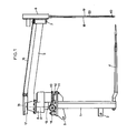
- - La figure 1 représente une vue de côté d'une machine selon l'invention,
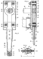
- - La figure 2 représente à plus grande échelle et partiellement en coupe, une vue de face du dispositif de coupe,
- - La figure 3 représente en coupe partielle une vue de côté du dispositif de coupe,
- - La figure 4 représente une coupe transversale des couteaux.
- Telle qu'elle est représentée sur la figure 1, la machine selon l'invention comporte un châssis (1) formant un cadre rigide. Ce châssis (1) possède trois points d'accouplement pour l'attelage à un tracteur d'entraînement non représenté. Ces points d'attelage sont constitués par deux tourillons inférieurs (2) et un tourillon supérieur (3). Ledit châssis est également pourvu à sa partie inférieure de plusieurs pointes (4) qui s'étendent dans un plan sensiblement horizontal. A une certaine distance au-dessus de ces pointes (4) est prévu un bras support (5) portant à son extrémité extérieure un dispositif de coupe (6). Celui-ci est articulé sur ledit bras au moyen d'un axe sensiblement vertical (7).
- Le bras support (5) du dispositif de coupe (6) est articulé dans un boîtier (8) au moyen d'un axe sensiblement vertical dont seul l'axe géométrique (9) est représenté sur la figure 1. Ce boîtier (8) est lui-même articulé sur un axe sensiblement vertical (10) qui est fixé sur une plaque (11) solidaire du châssis (1). A la base du boîtier (8) est prévue une couronne dentée (12) qui engrène avec une crémaillère (13) fixée sur le corps d'un vérin hydraulique (14) à double tige solidaire du châssis (1). Dans ledit boîtier (8) chacun des deux axes précités porte une roue dentée. Ces deux roues communiquent entre elles au moyen d'une roue dentée intermédiaire également logée dans le boîtier (8).
- Le déplacement de la tête de coupe (6) en vue du découpage d'un bloc est obtenu en faisant se déplacer longitudinalement le corps du vérin (14) et la crémaillère (13). Celle-ci fait alors tourner le boîtier (8) autour de l'axe (10), lequel boîtier déplace à son tour le bras support (5). Ce déplacement du bras support (5) s'opère dans la direction opposée à celle du boîtier (8) en raison de l'agencement des roues dentées précitées. En sus, la vitesse de rotation du bras support (5) sur son axe d'articulation avec le boîtier (8) est égale à quatre tiers de la vitesse de rotation dudit boîtier sur son axe (10). Cet agencement permet de déplacer le dispositif de coupe (6) suivant une trajectoire en forme de U en vue du découpage de blocs sensiblement rectangulaires.
- Durant ledit découpage, le dispositif de coupe (6) est orienté autour de l'axe d'articulation (7) avec le bras support (5) afin de le maintenir constamment tangent à sa trajectoire. Cette orientation est assurée au moyen d'une tringle (15) articulée sur le dispositif de coupe (6) et reliée à une seconde tringle (16) qui est commandée par une manivelle (17) reliée au boîtier support (8) par un axe traversant l'axe d'articulation du bras support (5).
- Comme cela ressort des figures 2 à 4, le dispositif de coupe (6) comporte deux couteaux dentés animés (18 et 19) qui s'étendent vers le bras pratiquement jusqu'au niveau des pointes (4) du châssis (1) et un couteau denté fixe (20) sensiblement parallèle auxdits couteaux animés (18, 19). Ces couteaux animés (18, 19) sont fixés sur des coulisseaux (21, 22) au moyen de vis (23 et 24). Les coulisseaux (21 et 22) s'étendent en grande partie dans un boîtier (25) formé par une plaque de fond (26) articulée sur le bras support (5) au moyen de l'axe d'articulation (7) comme décrit précédemment, et d'un couvercle (27). Dans ce boîtier (25) sont prévus des galets (28) pour le guidage des coulisseaux (21 et 22). Ces galets (28) sont montés sur des axes de serrage (29) et se situent de part et d'autre des coulisseaux (21 et 22). La plaque de fond (26) porte en sus un moteur hydraulique (30) pour entraîner en des mouvements rectilignes alternatifs les couteaux (18 et 19). A cet effet, l'axe (31) du moteur (30) est muni de deux excentriques (32 et 33) actionnant chacun un des coulisseaux (21, 22). Pour cela, chaque excentrique (32, 33) porte un roulement à billes (34) qui est engagé dans un orifice de forme oblongue (35) prévu dans chaque coulisseau (21, 22) (voir figures 2 et 3).
- Le couteau denté fixe (20) s'étend jusque dans le boîtier (25) et y est fixé sur les deux axes de serrage (29) inférieurs. On voit sur la figure 2 que l'extrémité du couteau fixe (20) qui se situe dans le boîtier (25) est élargie et comporte deux trous de passage (36) pour les axes de serrage (29).
- Dans le mode de réalisation représenté, le couteau denté fixe (20) se situe entre les deux couteaux animés (18 et 19). Dans ce cas, la largeur (1) du couteau fixe (20) est sensiblement égale à celle des couteaux animés (18 et 19) et son épaisseur (e) est très faible. Cette épaisseur (e) peut être de l'ordre de deux millimètres ou même inférieure à deux millimètres, selon la rigidité de la matière utilisée.
- Il est aussi possible de prévoir autant de couteaux fixes (20) que de couteaux animés (18, 19) ou même un couteau fixe (20) de part et d'autre de chaque couteau animé (18 ou 19), pour augmenter davantage l'effet de cisaillement.
- Il ressort également des figures 2 et 4 que le couteau fixe (20) comporte des dents (37) sur ses deux flancs. De cette manière, il coopère au découpage aussi bien de la gauche vers la droite qu'inversement de la droite vers la gauche. Le pas de ces dents (37) est sensiblement égal au pas des dents (38 et 39) des couteaux animés (18 et 19). Le nombre de croisements entre les arêtes des dents (37) du couteau fixe (20) et les arêtes des dents (38 et 39) des couteaux animés (18 et 19) est doublé par rapport au nombre de croisements existant sur un dispositif sans couteau fixe (20). L'effet de cisaillement ainsi obtenu convient parfaitement pour le découpage de la plupart des matières ensilées. Pour la coupe de matière particulièrement résistante, on peut utiliser des couteaux fixes comportant des dents avec un pas inférieur à celui des dents des couteaux animés, afin d'augmenter davantage l'effet de cisaillement. A l'inverse, dans des conditions de coupe plus faciles, on peut aussi utiliser des couteaux fixes sur lesquels le pas des dents est supérieur à celui des dents des couteaux animés.
- Il ressort par ailleurs des figures 2 et 4 que l'extrémité inférieure du couteau fixe (20) comporte des organes de guidage (40) des couteaux mobiles (18, 19). Lesdits organes sont constitués par des axes (41) s'étendant de part et d'autre du couteau fixe (20) et portant des arrêts (42 et 43) à leurs extrémités. Chaque couteau animé (18, 19) comporte une même ouverture oblongue (44) pour le passage desdits axes (41). Ces couteaux animés (18, 19) peuvent ainsi se déplacer verticalement par rapport au couteau fixe (20), tout en étant reliés à ce dernier. Cette liaison permet de maintenir les couteaux (18, 19 et 20) rapprochés de manière à favoriser la coupe.
- Il est bien évident que l'on pourra encore apporter à l'exemple de réalisation décrit ci-dessus divers perfectionnements, modifications ou additions ou remplacer certains éléments par des éléments équivalents sans pour autant sortir du cadre de la présente invention.
Claims (6)
Applications Claiming Priority (2)
| Application Number | Priority Date | Filing Date | Title |
|---|---|---|---|
| FR8702184 | 1987-02-16 | ||
| FR8702184A FR2610783B1 (fr) | 1987-02-16 | 1987-02-16 | Machine pour le prelevement de blocs de fourrage dans un silo |
Publications (2)
| Publication Number | Publication Date |
|---|---|
| EP0279760A1 true EP0279760A1 (fr) | 1988-08-24 |
| EP0279760B1 EP0279760B1 (fr) | 1991-03-20 |
Family
ID=9348106
Family Applications (1)
| Application Number | Title | Priority Date | Filing Date |
|---|---|---|---|
| EP19880440006 Expired - Lifetime EP0279760B1 (fr) | 1987-02-16 | 1988-02-03 | Machine pour le prélèvement de blocs de fourrage dans un silo |
Country Status (3)
| Country | Link |
|---|---|
| EP (1) | EP0279760B1 (fr) |
| DE (1) | DE3862042D1 (fr) |
| FR (1) | FR2610783B1 (fr) |
Citations (4)
| Publication number | Priority date | Publication date | Assignee | Title |
|---|---|---|---|---|
| US1537980A (en) * | 1922-06-09 | 1925-05-19 | Louis A G Asselin | Drag saw |
| GB776831A (en) * | 1954-03-12 | 1957-06-12 | Charles Alfred Smith | Improvements in or relating to hedge clippers and the like |
| US3016932A (en) * | 1959-08-18 | 1962-01-16 | John M Jacobson | Power operated saw having oppositely reciprocating blades |
| EP0081447A1 (fr) * | 1981-12-08 | 1983-06-15 | Kuhn S.A. | Perfectionnement aux machines pour le prélèvement de blocs de fourrage dans un silo |
-
1987
- 1987-02-16 FR FR8702184A patent/FR2610783B1/fr not_active Expired - Fee Related
-
1988
- 1988-02-03 DE DE8888440006T patent/DE3862042D1/de not_active Expired - Fee Related
- 1988-02-03 EP EP19880440006 patent/EP0279760B1/fr not_active Expired - Lifetime
Patent Citations (4)
| Publication number | Priority date | Publication date | Assignee | Title |
|---|---|---|---|---|
| US1537980A (en) * | 1922-06-09 | 1925-05-19 | Louis A G Asselin | Drag saw |
| GB776831A (en) * | 1954-03-12 | 1957-06-12 | Charles Alfred Smith | Improvements in or relating to hedge clippers and the like |
| US3016932A (en) * | 1959-08-18 | 1962-01-16 | John M Jacobson | Power operated saw having oppositely reciprocating blades |
| EP0081447A1 (fr) * | 1981-12-08 | 1983-06-15 | Kuhn S.A. | Perfectionnement aux machines pour le prélèvement de blocs de fourrage dans un silo |
Also Published As
| Publication number | Publication date |
|---|---|
| DE3862042D1 (de) | 1991-04-25 |
| EP0279760B1 (fr) | 1991-03-20 |
| FR2610783B1 (fr) | 1990-04-20 |
| FR2610783A1 (fr) | 1988-08-19 |
Similar Documents
| Publication | Publication Date | Title |
|---|---|---|
| EP0046427A1 (fr) | Dispositif de liage pour presses à balles cylindriques | |
| EP1250834B1 (fr) | Machine de fenaison comportant un dispositif de regroupement d'andains | |
| FR2549685A1 (fr) | Dispositif de recolte pour graminees, telles que le mais, disposees en rangees | |
| EP0279760B1 (fr) | Machine pour le prélèvement de blocs de fourrage dans un silo | |
| FR2722365A1 (fr) | Machine de fenaison, notamment une andaineuse de vegetaux a bras porte-fourches commandes | |
| FR2552616A1 (fr) | Machine pour travailler le sol, munie d'un moteur | |
| EP0064115A1 (fr) | Faucheuse-conditionneuse | |
| EP0280633B1 (fr) | Machine pour le prélèvement de blocs de fourrage dans un silo | |
| EP0517633B1 (fr) | Faucheuse perfectionnée | |
| EP0071555B1 (fr) | Machine pour le prélèvement de blocs de fourrage dans un silo | |
| EP0152363B1 (fr) | Machines pour le prélèvement de blocs de fourrage dans un silo | |
| EP0543688B1 (fr) | Dispositif de coupe pour désileuse | |
| EP0007543B1 (fr) | Métier à tisser avec dispositif coupe-trame et dispositif coupe-trame utilisé dans celui-ci | |
| EP0152364B1 (fr) | Machine pour le prélèvement de blocs de fourrage dans un silo, avec des moyens d'entraînement perfectionnés | |
| EP0162795B1 (fr) | Moyens d'entraînement de machines pour le prélèvement de blocs de fourrage | |
| FR2559023A1 (fr) | Hacheuse a roues a disque | |
| EP0081447B1 (fr) | Perfectionnement aux machines pour le prélèvement de blocs de fourrage dans un silo | |
| EP0338653B1 (fr) | Dispositif de chargement à système de coupe latéral pour désileuses distributrices | |
| FR2514229A1 (fr) | Machine pour le prelevement de blocs de fourrage dans un silo | |
| FR2635941A1 (fr) | Appareil rotatif de travail du sol | |
| FR2770370A1 (fr) | Desileuse distributrice pour des produits agricoles tels que du fourrage ou les produits emballes dans une balle enrubannee tres compacte | |
| EP0059815B1 (fr) | Dispositif de commande de liage pour presses à balles cylindriques | |
| FR2571927A1 (fr) | Entrainement pour le dispositif d'alimentation du produit recolte sur des presses a balles | |
| FR2640175A1 (fr) | Dispositif de sciage | |
| BE553117A (fr) |
Legal Events
| Date | Code | Title | Description |
|---|---|---|---|
| PUAI | Public reference made under article 153(3) epc to a published international application that has entered the european phase |
Free format text: ORIGINAL CODE: 0009012 |
|
| AK | Designated contracting states |
Kind code of ref document: A1 Designated state(s): DE FR NL |
|
| 17P | Request for examination filed |
Effective date: 19890105 |
|
| 17Q | First examination report despatched |
Effective date: 19900522 |
|
| GRAA | (expected) grant |
Free format text: ORIGINAL CODE: 0009210 |
|
| AK | Designated contracting states |
Kind code of ref document: B1 Designated state(s): DE FR NL |
|
| REF | Corresponds to: |
Ref document number: 3862042 Country of ref document: DE Date of ref document: 19910425 |
|
| PLBE | No opposition filed within time limit |
Free format text: ORIGINAL CODE: 0009261 |
|
| STAA | Information on the status of an ep patent application or granted ep patent |
Free format text: STATUS: NO OPPOSITION FILED WITHIN TIME LIMIT |
|
| 26N | No opposition filed | ||
| PGFP | Annual fee paid to national office [announced via postgrant information from national office to epo] |
Ref country code: DE Payment date: 19990126 Year of fee payment: 12 |
|
| PGFP | Annual fee paid to national office [announced via postgrant information from national office to epo] |
Ref country code: NL Payment date: 19990128 Year of fee payment: 12 |
|
| PGFP | Annual fee paid to national office [announced via postgrant information from national office to epo] |
Ref country code: FR Payment date: 19990225 Year of fee payment: 12 |
|
| PG25 | Lapsed in a contracting state [announced via postgrant information from national office to epo] |
Ref country code: NL Free format text: LAPSE BECAUSE OF NON-PAYMENT OF DUE FEES Effective date: 20000901 |
|
| PG25 | Lapsed in a contracting state [announced via postgrant information from national office to epo] |
Ref country code: FR Free format text: LAPSE BECAUSE OF NON-PAYMENT OF DUE FEES Effective date: 20001031 |
|
| NLV4 | Nl: lapsed or anulled due to non-payment of the annual fee |
Effective date: 20000901 |
|
| PG25 | Lapsed in a contracting state [announced via postgrant information from national office to epo] |
Ref country code: DE Free format text: LAPSE BECAUSE OF NON-PAYMENT OF DUE FEES Effective date: 20001201 |
|
| REG | Reference to a national code |
Ref country code: FR Ref legal event code: ST |