EP0279767A2 - Mit einem eingebauten Wassermantel versehene gasgefeuerte Raumheizungs- und Warmwasseranlage - Google Patents
Mit einem eingebauten Wassermantel versehene gasgefeuerte Raumheizungs- und Warmwasseranlage Download PDFInfo
- Publication number
- EP0279767A2 EP0279767A2 EP88630021A EP88630021A EP0279767A2 EP 0279767 A2 EP0279767 A2 EP 0279767A2 EP 88630021 A EP88630021 A EP 88630021A EP 88630021 A EP88630021 A EP 88630021A EP 0279767 A2 EP0279767 A2 EP 0279767A2
- Authority
- EP
- European Patent Office
- Prior art keywords
- heating
- hot water
- fluid
- water
- coil
- Prior art date
- Legal status (The legal status is an assumption and is not a legal conclusion. Google has not performed a legal analysis and makes no representation as to the accuracy of the status listed.)
- Granted
Links
Images


Classifications
-
- F—MECHANICAL ENGINEERING; LIGHTING; HEATING; WEAPONS; BLASTING
- F24—HEATING; RANGES; VENTILATING
- F24D—DOMESTIC- OR SPACE-HEATING SYSTEMS, e.g. CENTRAL HEATING SYSTEMS; DOMESTIC HOT-WATER SUPPLY SYSTEMS; ELEMENTS OR COMPONENTS THEREFOR
- F24D3/00—Hot-water central heating systems
- F24D3/08—Hot-water central heating systems in combination with systems for domestic hot-water supply
-
- F—MECHANICAL ENGINEERING; LIGHTING; HEATING; WEAPONS; BLASTING
- F24—HEATING; RANGES; VENTILATING
- F24H—FLUID HEATERS, e.g. WATER OR AIR HEATERS, HAVING HEAT-GENERATING MEANS, e.g. HEAT PUMPS, IN GENERAL
- F24H6/00—Combined water and air heaters
-
- F—MECHANICAL ENGINEERING; LIGHTING; HEATING; WEAPONS; BLASTING
- F24—HEATING; RANGES; VENTILATING
- F24H—FLUID HEATERS, e.g. WATER OR AIR HEATERS, HAVING HEAT-GENERATING MEANS, e.g. HEAT PUMPS, IN GENERAL
- F24H8/00—Fluid heaters characterised by means for extracting latent heat from flue gases by means of condensation
-
- Y—GENERAL TAGGING OF NEW TECHNOLOGICAL DEVELOPMENTS; GENERAL TAGGING OF CROSS-SECTIONAL TECHNOLOGIES SPANNING OVER SEVERAL SECTIONS OF THE IPC; TECHNICAL SUBJECTS COVERED BY FORMER USPC CROSS-REFERENCE ART COLLECTIONS [XRACs] AND DIGESTS
- Y02—TECHNOLOGIES OR APPLICATIONS FOR MITIGATION OR ADAPTATION AGAINST CLIMATE CHANGE
- Y02B—CLIMATE CHANGE MITIGATION TECHNOLOGIES RELATED TO BUILDINGS, e.g. HOUSING, HOUSE APPLIANCES OR RELATED END-USER APPLICATIONS
- Y02B30/00—Energy efficient heating, ventilation or air conditioning [HVAC]
Definitions
- This invention relates generally to a fluid heating system and, more particularly, to a heating system which utilizes an infrared burner module having a heat exchanger coil wrapped around a radiant burner to provide both domestic hot water and space heat.
- Air for a space to be heated circulates through a closed system (such as ductwork), and is heated either as it passes through a heat exchanger in contact with a burning fuel, or as it passes in contact with a secondary fluid which has been heated by a burning fuel. Since burning the fuel results in the production of noxious combustion gases having exhaust temperatures which can exceed 500°F, it is necessary to exhaust the combustion gases through a chimney or flue to the atmosphere.
- a closed system such as ductwork
- Indirect fired furnaces ones in which the air being heated is not contacted directly by the combustion gases generated, are generally used in both forced air systems and hydronic systems.
- a forced air system consists primarily of a heat exchanger having combustion chambers arranged in relation to the flow of air to be heated such that fuel is generally introduced at the lower end of the chamber where a flame causes heat to be generated.
- the heat rises through a series of internal baffles before exiting through an upper end of the combustion chamber into the flue or chimney. Simultaneously, circulated space air passes around the outside of the heat exchangers to absorb heat through conduction and convention.
- a hydronic system consists primarily of a firebox having a heat exchanger therein.
- the heat exchanger is located in a closed loop system for continuously circulating water from the heat exchanger to a remote radiator in the space to be heated.
- this system is also relatively inefficient and expensive due to the combustion gas temperatures at the outlet of the firebox and the cost of the chimney.
- potable hot water systems In supplying domestic hot water for homes and commercial buildings, potable hot water systems with ordinary glass-lined, hot water storage tanks are generally used. It is common for these systems to have an enclosed water tank in which the cold water to be heated enters. At the lowermost portion of the tank there is normally a burner whose heat is allowed to pass through the tank, thereby heating the water in the tank for use within the home or building. Again, as in the space heating systems for homes and buildings, the heat which is not transferred to the heat exchanger is exhausted at the top of the tank into a flue or chimney to the atmosphere.
- a domestic hot water system is also inefficient because a great portion of the heat is lost directly up the chimney to the atmosphere, both during demand/on time and standby/off time, as well as being lost through the tank jacket. In addition to the inefficiencies of these systems, the flues or chimneys are costly to construct.
- combustion roar Another problem in space heating installations and domestic hot water tanks is the loud low frequency noise associated with these systems commonly called combustion roar. This is especially true where the furnace is connected to a duct of the heating system which tends to amplify the noise.
- furnaces or water heaters normally generate gaseous combustion products which include oxides of nitrogen (NO X ) which are vented to the atmosphere as flue gases. It is desirable to limit these oxides of nitrogen emissions since oxides of nitrogen are considered pollutants, and gas-fired combustion systems sold in certain geographical areas must meet strict NO X emission standards.
- NO X oxides of nitrogen
- a further object of the present invention is to provide a single package heater having a sealed combustion module with a radiant burner which will produce low NO X emissions and provides through the wall air intake and discharge of combustion products, thereby eliminating a chimney.
- a heating system for heating a space having a closed fluid flow loop with a fluid pump for circulating the fluid in the loop and a remote fan coil for transferring heat to the air in the space to be heated, and a tube-in-tube heat exchanger to transfer heat from the closed loop to the domestic water to provide instantaneous and continuous hot water, and a liquid-backed heating module having an infrared burner and a heat exchanger coil wrapped around the burner, and a tube-in-tube heat exchanger for purposes of heating domestic hot water.
- FIG. 1 there may be seen a schematic view of a residential heating system 10 using a liquid-backed heating module 12 for supplying energy to the system.
- the heating system 10 includes heating module 12, remote radiator or fan coil 14, and a liquid pump 16.
- the remote fan coil 14 may typically be a plate fin heat exchanger or a radiator having air flowing therethrough in the direction of the arrow into the space 11 to be heated.
- Radiators are generally used in hydronic systems in which the air in the space to be heated is circulated by gravity. In a conventional forced air system air is drawn from the room through cold air ducts and, after passing around the heat exchanger in the furnace, is discharged through hot air ducts.
- a fan is incorporated in the furnace to provide forced circulation of the air between the furnace and the rooms or other space to be heated.
- the fan coil 14 is connected to the discharge of the heating module 12 by a pipe section 22.
- the fluid in the heating system circulates from the fan coil 14 through pipe section 24 to liquid pump 16 and then under the pressure of the liquid pump 16 is returned to the heating module 12 through pipe section 26.
- An expansion tank 28 is connected to pipe section 26 to provide volume for the expansion of the heated liquid and to dampen any pressure surges in the heating system.
- the heating module 12 includes a gas line 30 having a regulator 32 for supplying fuel to the module. Further, air is supplied to the module through line 34.
- Burner control 40 is a conventional furnace control and will not be described in detail herein.
- a spark ignition system is used to ignite the air/fuel mixture and a flame sensor is used to sense whether combustion actually occurs.
- the control system for example, may be a Honeywell Model S87D Direct Spark Ignition System. Still further as shown in Figure 1, domestic water enters the system through three-way valve 42, is heated in the heating module 12 and is returned to the domestic hot water system represented by tap 43 through three-way valve 44.
- the heating module 12 comprising a housing 20 with an infrared burner 18 located centrally therein. Air is supplied through air line 34 and fuel is supplied through regulator 32 and gas line 30 such that the air and gaseous fuel are 100% premixed, thus, no secondary combustion occurs.
- a heat exchange means 19 is located in spaced relation to the infrared burner 18 to receive heat from the infrared burner.
- the heat exchange means in the form of a helical coil has fluid, e.g. potable water, flowing therethrough which absorbs heat from the infrared burner 18 and transfers this heat to the fluid in the coil which flows through three-way valve 44 and/or flows to faucet 43 or to the space 11 to be conditioned by way of the remote fan coil 14.
- the heat exchange means 19 may preferably be a plurality of helical coils forming passageways for the combustion gases. Moreover, the heat exchange means 19 is heated by both radiation and convection heat transfer from the infrared burner 18. If the adjacent coils of a plurality of helical coils are closely spaced to form a plurality of walls, then, the combustion gases will flow along the inner wall of the inner coil and then between the inner and middle coil walls and between the outer coil wall and the middle coil wall to be discharged by the induction fan 38 to atmosphere.
- FIG. 2 there is shown an embodiment of a closed loop heating fluid system of the present invention using the same heating module 12 as hereinabove described, but using a series fluid loop for space heating and domestic hot water.
- This fluid loop arrangement as shown consists of discharge pipe 52 which extracts hot fluid from heating module 12 on demand.
- the heated fluid flows through a tube-in-tube heat exchanger 50 of conventional construction.
- the fluid then flows through pipe 54 and through three-way valve 56.
- the three-way valve 56 allows the fluid to flow directly to the liquid pump 16 through pipe 55 and back to the heating module 12 through pipe 57.
- the three-way valve 56 allows the fluid in the loop to flow through pipe 58 into fan coil 14 and through piep 59 back to the suction of liquid pump 16.
- domestic hot water loop includes cold water inlet pipe 62 connected to the inlet of tube-in-tube heat exchanger 50 and outlet pipe 64 which discharges hot domestic water to tap 43 after passing through flow switch 66.
- the flow switch senses water flow through the tap and sends an electrical signal through conductor 29 to a microprocessor control, not illustrated, which in response thereto sends a signal via conductor 29 ⁇ to energize the ignition device 40 and circulating pump 16.
- a mixing valve 60 connects pipe 64 to bypass pipe 65.
- Mixing valve 60 is preferably a temperature responsive valve which mixes the hot water flowing through the heat exchanger 50 and the cold water flowing through the bypass pipe 65 to ensure that the hot water flowing from the tap 43 is at a desired temperature such as 120°F.
- the mixing valve 60 may be, for example, a Tour-Anderson mixing valve.
- the heating module may advantageously have a heating capacity of 108,000 BTU/Hour.
- the closed loop fluid system including tube-in-tube heat exchanger 50, fan coil 14, connecting pipes, and helical coil 19 advantageously has a capacity of three gallons of fluid per minute at about 190°F for each 122,000 BTU/Hour heat input to the infrared burner.
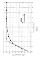
- Figure 3 exemplifies the heat transfer performance of the tube-in-tube heat exchanger for various hot water flows through tap 43.
- Curve 70 indicates the water temperature rise with respect to time for a 1 GPM flow through tap 43, while curve 70 ⁇ indicates the temperature per time for a 2 GPM flow.
- the fluid flow loop can supply the exact domestic hot water on demand with the remaining heat, if required, being supplied to the fan coil 14, which is in series but downstream of the tube-in-tube heat exchanger.
- flow switch 66 senses flow and sends a signal to initiate heating module 14 operation through ignition device 40, and fluid loop operation through liquid pump 16.
- heating module 12 is energized hot fluid flows through tube-in-tube heat exchanger to satisfy the domestic hot water demand.
- three-way valve 56 is positioned to a second position which allows the fluid also to flow through fan coil 14 to satisfy the need for space heat.
- the two-way valve 56 changes to a first position and the hot fluid bypasses the fan coil 14. Moreover, if the demand at tap 43 is decreased, such as by opening the tap only slightly, then mixing valve 60 allows cold water to flow through pipe 65 to ensure the hot water at the tap is at the desired temperature. Furthermore, if demand for hot water at tap 43 is high, coil 14 may also again be bypassed in order to prevent lower temperature, less comfortable air in the space to be heated.
Landscapes
- Engineering & Computer Science (AREA)
- Physics & Mathematics (AREA)
- Thermal Sciences (AREA)
- Chemical & Material Sciences (AREA)
- Combustion & Propulsion (AREA)
- Mechanical Engineering (AREA)
- General Engineering & Computer Science (AREA)
- Water Supply & Treatment (AREA)
- Steam Or Hot-Water Central Heating Systems (AREA)
- Instantaneous Water Boilers, Portable Hot-Water Supply Apparatuses, And Control Of Portable Hot-Water Supply Apparatuses (AREA)
Applications Claiming Priority (2)
| Application Number | Priority Date | Filing Date | Title |
|---|---|---|---|
| US17309 | 1987-02-20 | ||
| US07/017,309 US4738394A (en) | 1987-02-20 | 1987-02-20 | Integral liquid-backed gas-fired space heating and hot water system |
Publications (3)
| Publication Number | Publication Date |
|---|---|
| EP0279767A2 true EP0279767A2 (de) | 1988-08-24 |
| EP0279767A3 EP0279767A3 (en) | 1990-01-31 |
| EP0279767B1 EP0279767B1 (de) | 1992-12-30 |
Family
ID=21781885
Family Applications (1)
| Application Number | Title | Priority Date | Filing Date |
|---|---|---|---|
| EP88630021A Expired - Lifetime EP0279767B1 (de) | 1987-02-20 | 1988-02-08 | Mit einem eingebauten Wassermantel versehene gasgefeuerte Raumheizungs- und Warmwasseranlage |
Country Status (6)
| Country | Link |
|---|---|
| US (1) | US4738394A (de) |
| EP (1) | EP0279767B1 (de) |
| JP (1) | JPS63210558A (de) |
| CA (1) | CA1289023C (de) |
| DE (1) | DE3877014T2 (de) |
| ES (1) | ES2037270T3 (de) |
Cited By (4)
| Publication number | Priority date | Publication date | Assignee | Title |
|---|---|---|---|---|
| GB2234337B (en) * | 1989-06-22 | 1993-09-29 | Terance Gerard Madigan | A domestic water heating assembly |
| WO1998011391A1 (de) * | 1996-09-11 | 1998-03-19 | Limax Öl-Gas-Fernwärmetechnik Gmbh | Methode zur temperaturvorregelung ohne hilfsenergie für brauchwassererwärmungssysteme mit und ohne zirkulation und vorrichtungen dafür |
| US8107802B2 (en) | 2009-06-05 | 2012-01-31 | Jeremy Lee Hollis | Tankless electric water heater with efficient thermal transfer |
| US10704803B2 (en) | 2011-04-28 | 2020-07-07 | Seven International Group, Inc. | Infrared water heater |
Families Citing this family (19)
| Publication number | Priority date | Publication date | Assignee | Title |
|---|---|---|---|---|
| US5485879A (en) * | 1993-06-29 | 1996-01-23 | Bradford White Corporation | Combined water heater and heat exchanger |
| US5372185A (en) * | 1993-06-29 | 1994-12-13 | Bradford-White Corporation | Combined water heater and heat exchanger |
| US5660165A (en) * | 1994-06-07 | 1997-08-26 | Bradford White Corporation | Back-up heater |
| US6142216A (en) * | 1994-07-27 | 2000-11-07 | Bradford White Corporation | Indirect water heater |
| WO1999058904A1 (en) | 1998-05-13 | 1999-11-18 | Premark Feg L.L.C. | Gas fired booster |
| US6299071B1 (en) * | 1999-06-19 | 2001-10-09 | Stadler Viega, Llc | Hydronic heating with continuous circulation |
| US6681805B2 (en) * | 2001-11-28 | 2004-01-27 | Ranco Incorporated Of Delaware | Automotive coolant control valve |
| US6647932B1 (en) * | 2002-06-21 | 2003-11-18 | United Dominion Industries, Inc. | Compact boiler with tankless heater for providing heat and domestic hot water |
| US7007748B2 (en) * | 2003-09-30 | 2006-03-07 | Bradford White Corporation | Indirect water heater and method of manufacturing same |
| CA2451934C (en) * | 2003-12-02 | 2015-01-13 | International Thermal Investments Ltd. | Combination diesel/electric heating appliance systems |
| US7063132B2 (en) * | 2003-12-29 | 2006-06-20 | Bradford White Corporation | Multi-wall heat exchanger for a water heater |
| US20070205292A1 (en) * | 2006-03-01 | 2007-09-06 | Kyung Dong Boiler Co. Ltd. | Heated fluid distribution apparatus for combined domestic hot water supply and space heating system |
| US20070237501A1 (en) * | 2006-04-04 | 2007-10-11 | Kloster John M | Water heater for recreational vehicles having forced air/direct vent combustion |
| US8353463B2 (en) | 2007-04-24 | 2013-01-15 | Rinnai America Corporation | Methods and apparatus for heating air with hot water |
| WO2015196198A1 (en) | 2014-06-20 | 2015-12-23 | Pentair Water Pool And Spa, Inc. | Hybrid heater |
| US10012396B2 (en) * | 2014-11-18 | 2018-07-03 | Intellihot, Inc. | Combined space conditioning or heating and water heating system |
| US10612795B2 (en) | 2016-09-14 | 2020-04-07 | Lochinvar, Llc | Methods and system for demand-based control of a combination boiler |
| USD859618S1 (en) | 2017-09-15 | 2019-09-10 | Pentair Water Pool And Spa, Inc. | Heating apparatus clip |
| CN114674030A (zh) * | 2022-03-30 | 2022-06-28 | 江苏龙净科杰环保技术有限公司 | 一种新型供热水系统 |
Family Cites Families (11)
| Publication number | Priority date | Publication date | Assignee | Title |
|---|---|---|---|---|
| BE625646A (de) * | ||||
| DE1454520A1 (de) * | 1962-11-28 | 1969-02-06 | Wolff Ingemar Filip Paulus | Geschlossenes kombiniertes Heizungs- und Verbrauchswarmwassersystem |
| GB1093761A (en) * | 1965-06-22 | 1967-12-06 | Radiation Ltd | Improvements in or relating to central heating systems |
| DE1753212A1 (de) * | 1968-01-27 | 1971-07-29 | Peter Jokuszies | Warmwasserbereitung |
| JPS4948746B1 (de) * | 1970-08-04 | 1974-12-23 | ||
| DE2906555A1 (de) * | 1979-02-17 | 1980-10-30 | Vaillant Joh Gmbh & Co | Sammelheizung |
| FR2465958A1 (fr) * | 1979-09-24 | 1981-03-27 | Fonderie Soc Gen De | Installation de chauffage mixte |
| GB2060946B (en) * | 1979-10-09 | 1983-05-18 | Stelrad Group Ltd | Domestic heating system |
| US4403572A (en) * | 1980-05-16 | 1983-09-13 | Advanced Mechanical Technology, Inc. | Combustion product condensing water heater |
| US4484564A (en) * | 1982-07-28 | 1984-11-27 | Erickson Herbert V | Tap water preheater |
| FR2559574B1 (fr) * | 1984-02-15 | 1986-08-08 | Dantec Raymond | Dispositif de rechauffage de tuyauterie d'eau sanitaire notamment de locaux d'habitation |
-
1987
- 1987-02-20 US US07/017,309 patent/US4738394A/en not_active Expired - Lifetime
-
1988
- 1988-01-25 CA CA000557272A patent/CA1289023C/en not_active Expired - Lifetime
- 1988-02-08 EP EP88630021A patent/EP0279767B1/de not_active Expired - Lifetime
- 1988-02-08 DE DE8888630021T patent/DE3877014T2/de not_active Expired - Fee Related
- 1988-02-08 ES ES198888630021T patent/ES2037270T3/es not_active Expired - Lifetime
- 1988-02-17 JP JP63034945A patent/JPS63210558A/ja active Pending
Cited By (4)
| Publication number | Priority date | Publication date | Assignee | Title |
|---|---|---|---|---|
| GB2234337B (en) * | 1989-06-22 | 1993-09-29 | Terance Gerard Madigan | A domestic water heating assembly |
| WO1998011391A1 (de) * | 1996-09-11 | 1998-03-19 | Limax Öl-Gas-Fernwärmetechnik Gmbh | Methode zur temperaturvorregelung ohne hilfsenergie für brauchwassererwärmungssysteme mit und ohne zirkulation und vorrichtungen dafür |
| US8107802B2 (en) | 2009-06-05 | 2012-01-31 | Jeremy Lee Hollis | Tankless electric water heater with efficient thermal transfer |
| US10704803B2 (en) | 2011-04-28 | 2020-07-07 | Seven International Group, Inc. | Infrared water heater |
Also Published As
| Publication number | Publication date |
|---|---|
| US4738394A (en) | 1988-04-19 |
| EP0279767A3 (en) | 1990-01-31 |
| ES2037270T3 (es) | 1993-06-16 |
| DE3877014T2 (de) | 1993-04-15 |
| CA1289023C (en) | 1991-09-17 |
| DE3877014D1 (de) | 1993-02-11 |
| EP0279767B1 (de) | 1992-12-30 |
| JPS63210558A (ja) | 1988-09-01 |
Similar Documents
| Publication | Publication Date | Title |
|---|---|---|
| US4738394A (en) | Integral liquid-backed gas-fired space heating and hot water system | |
| EP0279765B1 (de) | Mit Gas beheizte Heizanlage mit Flüssigkeitsmantel | |
| US5076494A (en) | Integrated hot water supply and space heating system | |
| US4993402A (en) | Fuel efficient rapid response water heating module | |
| US4371111A (en) | Home heating system employing water heater as heating source | |
| US4974579A (en) | Induced draft, fuel-fired furnace apparatus having an improved, high efficiency heat exchanger | |
| US6109339A (en) | Heating system | |
| CA2123356C (en) | Ultra-high efficiency on-demand water heater | |
| US4412526A (en) | Water tempering system | |
| USRE33082E (en) | Combustion product condensing water heater | |
| US3315646A (en) | Boiler | |
| RU2095695C1 (ru) | Газовая печь полного сгорания | |
| CA1262411A (en) | Flue gas heat pump | |
| US3274990A (en) | Mass-production low-cost furnace for supplying high-temperature highvelocity air fordomestic heating | |
| US4122999A (en) | Forced air heating system | |
| GB2049128A (en) | Waste heat utilization system | |
| US4310746A (en) | Electric fluid heating apparatus | |
| US4880157A (en) | Capacity control for integrated furnace | |
| US5636786A (en) | High efficiency gas furnace | |
| US5282457A (en) | High efficiency gas furnace | |
| US6672255B1 (en) | Flue gas energy transfer system | |
| US4090492A (en) | Forced air furnace with liquid heat exchanger | |
| CN111351222B (zh) | 一种燃气壁挂炉 | |
| EP0069471B1 (de) | Heizgerät | |
| CA2028771C (en) | Integrated hot water supply and space heating system |
Legal Events
| Date | Code | Title | Description |
|---|---|---|---|
| PUAI | Public reference made under article 153(3) epc to a published international application that has entered the european phase |
Free format text: ORIGINAL CODE: 0009012 |
|
| AK | Designated contracting states |
Kind code of ref document: A2 Designated state(s): DE ES FR GB IT |
|
| PUAL | Search report despatched |
Free format text: ORIGINAL CODE: 0009013 |
|
| AK | Designated contracting states |
Kind code of ref document: A3 Designated state(s): DE ES FR GB IT |
|
| 17P | Request for examination filed |
Effective date: 19900608 |
|
| 17Q | First examination report despatched |
Effective date: 19910430 |
|
| GRAA | (expected) grant |
Free format text: ORIGINAL CODE: 0009210 |
|
| AK | Designated contracting states |
Kind code of ref document: B1 Designated state(s): DE ES FR GB IT |
|
| ET | Fr: translation filed | ||
| REF | Corresponds to: |
Ref document number: 3877014 Country of ref document: DE Date of ref document: 19930211 |
|
| ITF | It: translation for a ep patent filed | ||
| REG | Reference to a national code |
Ref country code: ES Ref legal event code: FG2A Ref document number: 2037270 Country of ref document: ES Kind code of ref document: T3 |
|
| PLBE | No opposition filed within time limit |
Free format text: ORIGINAL CODE: 0009261 |
|
| STAA | Information on the status of an ep patent application or granted ep patent |
Free format text: STATUS: NO OPPOSITION FILED WITHIN TIME LIMIT |
|
| 26N | No opposition filed | ||
| PGFP | Annual fee paid to national office [announced via postgrant information from national office to epo] |
Ref country code: FR Payment date: 20010111 Year of fee payment: 14 |
|
| PGFP | Annual fee paid to national office [announced via postgrant information from national office to epo] |
Ref country code: GB Payment date: 20010118 Year of fee payment: 14 |
|
| PGFP | Annual fee paid to national office [announced via postgrant information from national office to epo] |
Ref country code: DE Payment date: 20010119 Year of fee payment: 14 |
|
| PGFP | Annual fee paid to national office [announced via postgrant information from national office to epo] |
Ref country code: ES Payment date: 20010207 Year of fee payment: 14 |
|
| REG | Reference to a national code |
Ref country code: GB Ref legal event code: IF02 |
|
| PG25 | Lapsed in a contracting state [announced via postgrant information from national office to epo] |
Ref country code: GB Free format text: LAPSE BECAUSE OF NON-PAYMENT OF DUE FEES Effective date: 20020208 |
|
| PG25 | Lapsed in a contracting state [announced via postgrant information from national office to epo] |
Ref country code: ES Free format text: LAPSE BECAUSE OF NON-PAYMENT OF DUE FEES Effective date: 20020209 |
|
| PG25 | Lapsed in a contracting state [announced via postgrant information from national office to epo] |
Ref country code: DE Free format text: LAPSE BECAUSE OF NON-PAYMENT OF DUE FEES Effective date: 20020903 |
|
| GBPC | Gb: european patent ceased through non-payment of renewal fee |
Effective date: 20020208 |
|
| PG25 | Lapsed in a contracting state [announced via postgrant information from national office to epo] |
Ref country code: FR Free format text: LAPSE BECAUSE OF NON-PAYMENT OF DUE FEES Effective date: 20021031 |
|
| REG | Reference to a national code |
Ref country code: FR Ref legal event code: ST |
|
| REG | Reference to a national code |
Ref country code: ES Ref legal event code: FD2A Effective date: 20031122 |
|
| PG25 | Lapsed in a contracting state [announced via postgrant information from national office to epo] |
Ref country code: IT Free format text: LAPSE BECAUSE OF NON-PAYMENT OF DUE FEES;WARNING: LAPSES OF ITALIAN PATENTS WITH EFFECTIVE DATE BEFORE 2007 MAY HAVE OCCURRED AT ANY TIME BEFORE 2007. THE CORRECT EFFECTIVE DATE MAY BE DIFFERENT FROM THE ONE RECORDED. Effective date: 20050208 |