EP0279879A1 - Transmission d'impulsions par friction - Google Patents
Transmission d'impulsions par friction Download PDFInfo
- Publication number
- EP0279879A1 EP0279879A1 EP87102594A EP87102594A EP0279879A1 EP 0279879 A1 EP0279879 A1 EP 0279879A1 EP 87102594 A EP87102594 A EP 87102594A EP 87102594 A EP87102594 A EP 87102594A EP 0279879 A1 EP0279879 A1 EP 0279879A1
- Authority
- EP
- European Patent Office
- Prior art keywords
- flexible elements
- guide shaft
- crank pin
- flexible
- output shaft
- Prior art date
- Legal status (The legal status is an assumption and is not a legal conclusion. Google has not performed a legal analysis and makes no representation as to the accuracy of the status listed.)
- Granted
Links
- 230000001105 regulatory effect Effects 0.000 claims abstract description 5
- 230000007246 mechanism Effects 0.000 claims description 7
- 230000005540 biological transmission Effects 0.000 abstract description 4
- 238000006073 displacement reaction Methods 0.000 abstract description 4
- 238000012423 maintenance Methods 0.000 description 1
- 238000011089 mechanical engineering Methods 0.000 description 1
Images

Classifications
-
- F—MECHANICAL ENGINEERING; LIGHTING; HEATING; WEAPONS; BLASTING
- F16—ENGINEERING ELEMENTS AND UNITS; GENERAL MEASURES FOR PRODUCING AND MAINTAINING EFFECTIVE FUNCTIONING OF MACHINES OR INSTALLATIONS; THERMAL INSULATION IN GENERAL
- F16H—GEARING
- F16H29/00—Gearings for conveying rotary motion with intermittently-driving members, e.g. with freewheel action
-
- F—MECHANICAL ENGINEERING; LIGHTING; HEATING; WEAPONS; BLASTING
- F16—ENGINEERING ELEMENTS AND UNITS; GENERAL MEASURES FOR PRODUCING AND MAINTAINING EFFECTIVE FUNCTIONING OF MACHINES OR INSTALLATIONS; THERMAL INSULATION IN GENERAL
- F16H—GEARING
- F16H29/00—Gearings for conveying rotary motion with intermittently-driving members, e.g. with freewheel action
- F16H29/02—Gearings for conveying rotary motion with intermittently-driving members, e.g. with freewheel action between one of the shafts and an oscillating or reciprocating intermediate member, not rotating with either of the shafts
- F16H29/10—Gearings for conveying rotary motion with intermittently-driving members, e.g. with freewheel action between one of the shafts and an oscillating or reciprocating intermediate member, not rotating with either of the shafts in which the transmission ratio is changed by directly acting on the intermittently driving members
-
- Y—GENERAL TAGGING OF NEW TECHNOLOGICAL DEVELOPMENTS; GENERAL TAGGING OF CROSS-SECTIONAL TECHNOLOGIES SPANNING OVER SEVERAL SECTIONS OF THE IPC; TECHNICAL SUBJECTS COVERED BY FORMER USPC CROSS-REFERENCE ART COLLECTIONS [XRACs] AND DIGESTS
- Y10—TECHNICAL SUBJECTS COVERED BY FORMER USPC
- Y10T—TECHNICAL SUBJECTS COVERED BY FORMER US CLASSIFICATION
- Y10T74/00—Machine element or mechanism
- Y10T74/15—Intermittent grip type mechanical movement
- Y10T74/1503—Rotary to intermittent unidirectional motion
- Y10T74/1508—Rotary crank or eccentric drive
- Y10T74/151—Adjustable
-
- Y—GENERAL TAGGING OF NEW TECHNOLOGICAL DEVELOPMENTS; GENERAL TAGGING OF CROSS-SECTIONAL TECHNOLOGIES SPANNING OVER SEVERAL SECTIONS OF THE IPC; TECHNICAL SUBJECTS COVERED BY FORMER USPC CROSS-REFERENCE ART COLLECTIONS [XRACs] AND DIGESTS
- Y10—TECHNICAL SUBJECTS COVERED BY FORMER USPC
- Y10T—TECHNICAL SUBJECTS COVERED BY FORMER US CLASSIFICATION
- Y10T74/00—Machine element or mechanism
- Y10T74/15—Intermittent grip type mechanical movement
- Y10T74/1558—Grip units and features
- Y10T74/1587—Grip features
- Y10T74/1589—Driving band
- Y10T74/159—Clamping
Definitions
- the invention relates to a pulse friction gear with a guide shaft and an output shaft, which is comprised of at least one flexible element.
- Such pulse friction gears are used in mechanical engineering and in the electrical industry to drive mechanisms.
- a pulse friction gear which has a guide shaft with a ratchet mechanism and an output shaft, which is formed by two truncated cones, which are arranged side by side on two parallel axes that the large base of one truncated cone is assigned to the small base of the other truncated cone and that are surrounded by a flexible movable element.
- a disadvantage of the known pulse friction gear is that the range of the speed regulation is small due to the shift in the pulse friction gear with a large diameter difference of the truncated cones, and the truncated cones quickly wear out due to their displacement when locked with the pawl mechanism in order to obtain a pulse rotation.
- the object of the invention is to provide a pulse friction gear with a wide range for the rotation control and with a reduced displacement between the flexible element and the output shaft with increased operating time and with a constant transmission ratio.
- the guide shaft is a crankshaft with a guide shaft section and a coaxial first crank pin section, to each of which a crank arm is attached, which is parallel to one another parallel to the axis of the guide shaft section and the first crank pin section second crank pin section, that two flexible elements are provided, each of which is connected at one end to a crank pin section of the guide shaft and at the other end to a tensioning means, and that in the zone between the end points of the contact of the flexible elements with the output shaft and a further tensioning means for the flexible elements is fastened to the connection points of the flexible elements with the guide shaft.
- the one tensioning means of the flexible elements is expediently a spring, while the further tensioning means is also a spring which is connected to a mechanism that changes its force.
- the one clamping means of the flexible elements is advantageously a positionally fixed element, which has both ends at the ends of the flexible elements is connected in a hinge-like manner, a tension spring being fastened in a hinge-like manner to the center of the fixed element, while the further tensioning means has a further position-fixed element which is hinged at its two ends to the flexible elements and which is fixed in the middle with a stationary one regulating clamping device is connected.
- the guide shaft used according to the invention is a crankshaft, the crank pin sections of which are each connected to a flexible element and have a spacing of 180 °.
- the advantages of the pulse friction transmission according to the invention consist in a rotation control in a wide range, in a reduced displacement between the flexible elements and the output shaft, in a substantial increase in operating time and reliability and in the maintenance of a constant transmission ratio.
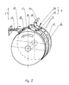
- the pulse friction gear shown in FIGS. 1 and 2 has an output shaft 1, around which two flexible elements 2 and 3 extend, each with its one end on a crank pin section 15 and 16 of a guide shaft 4 and with their other end are each fastened to a clamping device I.
- the axis of the first crank pin section 15 coincides with the axis of a guide shaft section of the guide shaft 4.
- the axis of the second crank pin section 16 is parallel to this common axis and away from it by the distance of the crank webs holding it.
- the two crank pin sections 15 and 16 are thus at a distance of 180 ° from one another.
- the tensioning means I of the flexible elements 2 and 3 each have a spring 5 or 6.
- the clamping means II is in each case a spring 8, which is connected to a mechanism 9 that changes its force.
- the tensioning means I comprises a fixed element 10, which is connected with its two ends in a hinge-like manner to the corresponding ends of the flexible elements 2 and 3.
- a tension spring 11 is fastened in a hinge-like manner via a holder 12.
- the further clamping means II for the flexible elements 2 and 3 is a fixed element 13, which is connected at both ends to the flexible elements 2 and 3 in a hinge-like manner.
- the fixed element 13 is connected in the middle like a hinge to a regulating fixed clamping device 14.
- the pulse friction gear works as follows:
- a sag occurs in the zone between the guide shaft 4 and the points 7 of the contact of the flexible elements 2 and 3 on the output shaft 1 of the flexible elements 2 and 3.
- the guide shaft 4 In order for the guide shaft 4 to set one of the flexible elements 2 or 3 into rotation in the direction of rotation of the output shaft 1, it must remove the sag of the flexible elements 2 and 3. If this sag is larger than the gear of the guide shaft 4, the output shaft 1 stops rotating.
Landscapes
- Engineering & Computer Science (AREA)
- General Engineering & Computer Science (AREA)
- Mechanical Engineering (AREA)
- Transmission Devices (AREA)
- Springs (AREA)
Priority Applications (1)
| Application Number | Priority Date | Filing Date | Title |
|---|---|---|---|
| DE8787102594T DE3765541D1 (de) | 1987-02-24 | 1987-02-24 | Impulsreibungsgetriebe. |
Applications Claiming Priority (1)
| Application Number | Priority Date | Filing Date | Title |
|---|---|---|---|
| US06/947,017 US4753120A (en) | 1986-12-29 | 1986-12-29 | Friction impulse transmission mechanism |
Publications (2)
| Publication Number | Publication Date |
|---|---|
| EP0279879A1 true EP0279879A1 (fr) | 1988-08-31 |
| EP0279879B1 EP0279879B1 (fr) | 1990-10-10 |
Family
ID=25485375
Family Applications (1)
| Application Number | Title | Priority Date | Filing Date |
|---|---|---|---|
| EP87102594A Expired - Lifetime EP0279879B1 (fr) | 1986-12-29 | 1987-02-24 | Transmission d'impulsions par friction |
Country Status (2)
| Country | Link |
|---|---|
| US (1) | US4753120A (fr) |
| EP (1) | EP0279879B1 (fr) |
Families Citing this family (1)
| Publication number | Priority date | Publication date | Assignee | Title |
|---|---|---|---|---|
| AU4344896A (en) * | 1995-12-13 | 1997-07-03 | Nl Consult Bv | Transmission |
Citations (4)
| Publication number | Priority date | Publication date | Assignee | Title |
|---|---|---|---|---|
| BE435036A (fr) * | ||||
| US3004440A (en) * | 1957-11-16 | 1961-10-17 | Ustav Pro Vyzkum Motorovych Vo | Continuously variable speed transmission |
| CH403428A (de) * | 1962-07-09 | 1965-11-30 | Sig Schweiz Industrieges | Getriebe mit stufenlos veränderbarem Übersetzungsverhältnis |
| GB1144963A (en) * | 1966-02-16 | 1969-03-12 | Belge Atel Reunies | A device for controlling the rotation of a slowly rotating drum-like member |
Family Cites Families (9)
| Publication number | Priority date | Publication date | Assignee | Title |
|---|---|---|---|---|
| US844730A (en) * | 1906-12-06 | 1907-02-19 | Daniel E Krause | Clutching device. |
| US1396335A (en) * | 1916-12-28 | 1921-11-08 | Marguerite V O Leary | Constant-speed vibrating motor and method |
| US1379212A (en) * | 1918-03-27 | 1921-05-24 | Marguerite V O Leary | Vibration-motor |
| US1700562A (en) * | 1925-10-20 | 1929-01-29 | Excello Transmission Company | Adjustable eccentric drive for transmissions |
| GB862907A (en) * | 1959-09-25 | 1961-03-15 | Arthur Mihalka Maroth | Improvements in or relating to torque converting apparatus |
| FR1361222A (fr) * | 1963-06-28 | 1964-05-15 | Sig Schweiz Industrieges | Transmission dont le rapport peut varier de façon continue |
| US3340743A (en) * | 1964-12-28 | 1967-09-12 | Sterling O Stageberg | Variable speed power transmission with flexible band and drive link |
| US3404616A (en) * | 1966-07-21 | 1968-10-08 | Bell & Howell Co | Drive mechanism with intermittently powered band |
| US4242050A (en) * | 1980-02-14 | 1980-12-30 | Oakes Richard M | Windmill power generator |
-
1986
- 1986-12-29 US US06/947,017 patent/US4753120A/en not_active Expired - Fee Related
-
1987
- 1987-02-24 EP EP87102594A patent/EP0279879B1/fr not_active Expired - Lifetime
Patent Citations (4)
| Publication number | Priority date | Publication date | Assignee | Title |
|---|---|---|---|---|
| BE435036A (fr) * | ||||
| US3004440A (en) * | 1957-11-16 | 1961-10-17 | Ustav Pro Vyzkum Motorovych Vo | Continuously variable speed transmission |
| CH403428A (de) * | 1962-07-09 | 1965-11-30 | Sig Schweiz Industrieges | Getriebe mit stufenlos veränderbarem Übersetzungsverhältnis |
| GB1144963A (en) * | 1966-02-16 | 1969-03-12 | Belge Atel Reunies | A device for controlling the rotation of a slowly rotating drum-like member |
Also Published As
| Publication number | Publication date |
|---|---|
| EP0279879B1 (fr) | 1990-10-10 |
| US4753120A (en) | 1988-06-28 |
Similar Documents
| Publication | Publication Date | Title |
|---|---|---|
| EP0036198B1 (fr) | Transmission à courroie embrayable | |
| DE19514812A1 (de) | Industrieroboter | |
| DE3503112C2 (fr) | ||
| DE2735958C3 (de) | Lenkgetriebe fur Kraftfahrzeuge | |
| EP0093189B1 (fr) | Dispositif d'alimentation pour fils de trame ou pareils à des machines textiles | |
| DE3828277C2 (de) | An einer Tragschiene anbringbare Schalteinheit mit zwei elektromagnetischen Kontakteinrichtungen | |
| DE3534446A1 (de) | Brennkraftmaschine mit zwei nebeneinander angeordneten nockenwellen | |
| DE3133729C2 (de) | Schwingantriebsvorrichtung | |
| DE69105744T2 (de) | Verfahren und vorrichtung um eine fläche bei hin- und hergehender bewegung in eine ebene zu führen. | |
| DE3129648C2 (de) | Sicherungsvorrichtung gegen ungewolltes Abrollen eines Rolltores | |
| DE3402187C1 (de) | Antrieb mit einem endlosen,zweiseitig verzahnten und in eine Zahnstange eingreifenden Treibelement | |
| CH664039A5 (de) | Einrichtung zur anpassung der wirkung eines elektromagneten an eine vom elektromagneten zu betaetigende komponente. | |
| DE3702502A1 (de) | Manipulatormodul | |
| EP0145848B1 (fr) | Immobilisation du sélecteur dans un dispositif de commande de vitesses | |
| DE3027060C2 (de) | Wellenkupplung | |
| DE2336863C3 (de) | Farbbandumschaltvorrichtung zum Umschalten der Längsbewegungsrichtung des Farbbandes z.B. eines Druckers | |
| EP0279879B1 (fr) | Transmission d'impulsions par friction | |
| DE69109270T2 (de) | Spannvorrichtung mit dazwischen liegender membran. | |
| DE3223419C2 (fr) | ||
| DE2941361C2 (de) | Seiltrieb | |
| DE3412147A1 (de) | Vorrichtung zur umwandlung einer drehbewegung in translatorische bewegungen | |
| DE10045919A1 (de) | Vorrichtung zum Steuern eines Spulenrahmens einer Textilmaschine | |
| DE2119461C3 (de) | Vorrichtung zur Umwandlung einer Eingangsbewegung in einen Zeigerausschlag | |
| DE3308263C2 (de) | Rollenförderbahn | |
| DE3315126C2 (de) | Scheibenwischeranlage, insbesondere Einarm- Scheibenwischeranlage für Kraftwagen |
Legal Events
| Date | Code | Title | Description |
|---|---|---|---|
| PUAI | Public reference made under article 153(3) epc to a published international application that has entered the european phase |
Free format text: ORIGINAL CODE: 0009012 |
|
| AK | Designated contracting states |
Kind code of ref document: A1 Designated state(s): BE DE FR GB IT SE |
|
| 17P | Request for examination filed |
Effective date: 19881213 |
|
| 17Q | First examination report despatched |
Effective date: 19890621 |
|
| GRAA | (expected) grant |
Free format text: ORIGINAL CODE: 0009210 |
|
| AK | Designated contracting states |
Kind code of ref document: B1 Designated state(s): BE DE FR GB IT SE |
|
| REF | Corresponds to: |
Ref document number: 3765541 Country of ref document: DE Date of ref document: 19901115 |
|
| ET | Fr: translation filed | ||
| ITF | It: translation for a ep patent filed | ||
| GBT | Gb: translation of ep patent filed (gb section 77(6)(a)/1977) | ||
| PGFP | Annual fee paid to national office [announced via postgrant information from national office to epo] |
Ref country code: GB Payment date: 19910201 Year of fee payment: 5 |
|
| PGFP | Annual fee paid to national office [announced via postgrant information from national office to epo] |
Ref country code: BE Payment date: 19910213 Year of fee payment: 5 |
|
| PGFP | Annual fee paid to national office [announced via postgrant information from national office to epo] |
Ref country code: SE Payment date: 19910218 Year of fee payment: 5 |
|
| PGFP | Annual fee paid to national office [announced via postgrant information from national office to epo] |
Ref country code: FR Payment date: 19910225 Year of fee payment: 5 |
|
| ITTA | It: last paid annual fee | ||
| PGFP | Annual fee paid to national office [announced via postgrant information from national office to epo] |
Ref country code: DE Payment date: 19910426 Year of fee payment: 5 |
|
| PLBE | No opposition filed within time limit |
Free format text: ORIGINAL CODE: 0009261 |
|
| STAA | Information on the status of an ep patent application or granted ep patent |
Free format text: STATUS: NO OPPOSITION FILED WITHIN TIME LIMIT |
|
| 26N | No opposition filed | ||
| PG25 | Lapsed in a contracting state [announced via postgrant information from national office to epo] |
Ref country code: GB Effective date: 19920224 |
|
| PG25 | Lapsed in a contracting state [announced via postgrant information from national office to epo] |
Ref country code: SE Effective date: 19920225 |
|
| PG25 | Lapsed in a contracting state [announced via postgrant information from national office to epo] |
Ref country code: BE Effective date: 19920228 |
|
| BERE | Be: lapsed |
Owner name: NPSK PO KONTROLNO SAVARATSCHNI RABOTI Effective date: 19920228 |
|
| GBPC | Gb: european patent ceased through non-payment of renewal fee | ||
| PG25 | Lapsed in a contracting state [announced via postgrant information from national office to epo] |
Ref country code: FR Effective date: 19921030 |
|
| PG25 | Lapsed in a contracting state [announced via postgrant information from national office to epo] |
Ref country code: DE Effective date: 19921103 |
|
| REG | Reference to a national code |
Ref country code: FR Ref legal event code: ST |
|
| EUG | Se: european patent has lapsed |
Ref document number: 87102594.6 Effective date: 19920904 |
|
| PG25 | Lapsed in a contracting state [announced via postgrant information from national office to epo] |
Ref country code: IT Free format text: LAPSE BECAUSE OF NON-PAYMENT OF DUE FEES;WARNING: LAPSES OF ITALIAN PATENTS WITH EFFECTIVE DATE BEFORE 2007 MAY HAVE OCCURRED AT ANY TIME BEFORE 2007. THE CORRECT EFFECTIVE DATE MAY BE DIFFERENT FROM THE ONE RECORDED. Effective date: 20050224 |