EP0279926B1 - Positionsbestimmungsverfahren innerhalb des Messraumes eines Koordinatenmessgerätes und dergleichen und System dafür - Google Patents
Positionsbestimmungsverfahren innerhalb des Messraumes eines Koordinatenmessgerätes und dergleichen und System dafür Download PDFInfo
- Publication number
- EP0279926B1 EP0279926B1 EP19870117850 EP87117850A EP0279926B1 EP 0279926 B1 EP0279926 B1 EP 0279926B1 EP 19870117850 EP19870117850 EP 19870117850 EP 87117850 A EP87117850 A EP 87117850A EP 0279926 B1 EP0279926 B1 EP 0279926B1
- Authority
- EP
- European Patent Office
- Prior art keywords
- data
- probe
- cmm
- axes
- function
- Prior art date
- Legal status (The legal status is an assumption and is not a legal conclusion. Google has not performed a legal analysis and makes no representation as to the accuracy of the status listed.)
- Expired
Links
- 238000000034 method Methods 0.000 title claims description 53
- 239000000523 sample Substances 0.000 claims description 97
- 238000005259 measurement Methods 0.000 claims description 40
- 230000033001 locomotion Effects 0.000 claims description 36
- 238000012937 correction Methods 0.000 claims description 28
- 230000008569 process Effects 0.000 claims description 9
- 238000003860 storage Methods 0.000 claims description 9
- 230000008878 coupling Effects 0.000 claims description 2
- 238000010168 coupling process Methods 0.000 claims description 2
- 238000005859 coupling reaction Methods 0.000 claims description 2
- 238000007689 inspection Methods 0.000 description 19
- 230000006870 function Effects 0.000 description 10
- 238000004519 manufacturing process Methods 0.000 description 9
- 238000013459 approach Methods 0.000 description 7
- 230000008901 benefit Effects 0.000 description 7
- 239000013598 vector Substances 0.000 description 7
- 239000010438 granite Substances 0.000 description 6
- 238000012545 processing Methods 0.000 description 6
- 229910000831 Steel Inorganic materials 0.000 description 4
- 239000010959 steel Substances 0.000 description 4
- 238000012546 transfer Methods 0.000 description 4
- 238000013461 design Methods 0.000 description 3
- 238000010586 diagram Methods 0.000 description 3
- 230000000694 effects Effects 0.000 description 3
- 239000011521 glass Substances 0.000 description 3
- 239000007787 solid Substances 0.000 description 3
- 238000004458 analytical method Methods 0.000 description 2
- 238000004364 calculation method Methods 0.000 description 2
- 238000006243 chemical reaction Methods 0.000 description 2
- 238000003754 machining Methods 0.000 description 2
- 238000003908 quality control method Methods 0.000 description 2
- 238000012360 testing method Methods 0.000 description 2
- 238000009825 accumulation Methods 0.000 description 1
- 238000004891 communication Methods 0.000 description 1
- 238000004590 computer program Methods 0.000 description 1
- 238000011161 development Methods 0.000 description 1
- 238000009826 distribution Methods 0.000 description 1
- 238000011156 evaluation Methods 0.000 description 1
- 238000007667 floating Methods 0.000 description 1
- 230000003993 interaction Effects 0.000 description 1
- 239000000463 material Substances 0.000 description 1
- 239000002184 metal Substances 0.000 description 1
- 238000012986 modification Methods 0.000 description 1
- 230000004048 modification Effects 0.000 description 1
- 238000012795 verification Methods 0.000 description 1
Images





Classifications
-
- G—PHYSICS
- G01—MEASURING; TESTING
- G01B—MEASURING LENGTH, THICKNESS OR SIMILAR LINEAR DIMENSIONS; MEASURING ANGLES; MEASURING AREAS; MEASURING IRREGULARITIES OF SURFACES OR CONTOURS
- G01B21/00—Measuring arrangements or details thereof, where the measuring technique is not covered by the other groups of this subclass, unspecified or not relevant
- G01B21/02—Measuring arrangements or details thereof, where the measuring technique is not covered by the other groups of this subclass, unspecified or not relevant for measuring length, width, or thickness
- G01B21/04—Measuring arrangements or details thereof, where the measuring technique is not covered by the other groups of this subclass, unspecified or not relevant for measuring length, width, or thickness by measuring coordinates of points
- G01B21/045—Correction of measurements
-
- G—PHYSICS
- G01—MEASURING; TESTING
- G01B—MEASURING LENGTH, THICKNESS OR SIMILAR LINEAR DIMENSIONS; MEASURING ANGLES; MEASURING AREAS; MEASURING IRREGULARITIES OF SURFACES OR CONTOURS
- G01B7/00—Measuring arrangements characterised by the use of electric or magnetic techniques
- G01B7/004—Measuring arrangements characterised by the use of electric or magnetic techniques for measuring coordinates of points
- G01B7/008—Measuring arrangements characterised by the use of electric or magnetic techniques for measuring coordinates of points using coordinate measuring machines
Definitions
- This invention relates to method and system for determining position within the measuring volume of a coordinate measuring machine (CMM) and, in particular, to method and system for determining position within the measuring volume of a CMM whereby the CMM is calibrated so that it is capable of determining position for its entire measuring volume.
- CMM coordinate measuring machine
- the CMM was developed in the early 1960's.
- a CMM can also be used as a layout machine before machining and for checking feature locations after machining. In many cases the CMM plays a vital role in the mechanization of the inspection process.
- the CMM Since its development, the CMM has been increasingly used throughout the automotive and aerospace industries. Although it was once considered an exotic tool for ensuring quality control, the CMM is now becoming a mandatory piece of equipment for both the large manufacturing plant and the small job shop. This is primarily due to the need for an accurate measuring instrument and detailed documentation of the components being produced.
- the CMM is being used in one of three ways in manufacturing.
- the simplest approach is to place the CMM at the end of the production line or in an inspection area.
- the CMM is used to inspect the first part of a production run to verify the machine setup. Once the setup is verified, it then measures parts on a random basis. For many applications, this permits the best approach to inspection.
- Another approach is to incorporate the CMM between two work centers and then measure 100% of the parts produced at the first center before any secondary operations are performed at the second work center.
- This approach is possible because CMMs are capable of measuring three-dimensional geometry and making many different measurements within a short period of time.
- the CMM indirectly controls the production process. In this setting, however, the CMM must be "hardened" to perform in the shop environment for part inspection.
- a third approach integrates the CMM into the production line. This permits the CMM to directly control the production process.
- an integrated system would measure the workpiece, compare the measurements with required dimensions and, if necessary, automatically adjust the machine controls so that the part is manufactured within the required specifications.
- a basic CMM consists of four elements: (1) the machine structure, which basically is an X-Y-Z positioning device; (2) the probing system used to detect part surfaces and provide input to a control system; (3) the control system including a machine control and computer hardware; and (4) the software for three-dimensional geometry analysis.
- the measuring envelope or volume is defined by the X, Y and Z travel of the machine.
- Each axis is ideally square in its own relationship to the reference plane created by the other two axes.
- Each axis is fitted with a linear measurement transducer for positional feedback. This allows position displays within the envelope to be independent of any fixed reference point.
- the most common reference systems in use are steel and glass scales. Both systems utilize noncontact, electro-optical reader heads for determining the exact position of the machine.
- Steel reference systems are widely used in shop environments because the difference in the coefficient of expansion between the steel scale and workpiece is minimal.
- Glass scale reference systems are generally used in controlled environments because of the difference in the coefficient of expansion between glass and the metal workpiece.
- the worktable of the machine generally contains tapped holes to facilitate the clamping and locating of parts. It may be made from granite or steel because of its stability in various environments.
- Probe arm or shaft which is supported by cantilever, bridge gantry, column members or other CMM types. Probe arm movement is guided by means of frictionless air bearings or mechanical bearings.
- Coordinate measuring is typically a two or three-dimensional process that determines the position of holes, surfaces, centerlines, and slopes. Up to six sides of a cube-shaped part may be inspected without repositioning the part.
- the part is placed on the table of the CMM at a random location. Generally, this location is approximately central to the machine axes to access all of the part surfaces to be inspected with the probe. Depending on the size of the part and the type of probe used, the part may need to be clamped to the machine table. If multiple inspections of similar parts are required, a reference location point may be established with a reference precision cube or sphere.
- the probe is then moved, manually or under machine control, until contact is made with desired part features. Reader heads, traveling on each axis along built-in axis measuring scales, transfer the instantaneous machine position through the digital display and to the computer interface. The dimensional and geometric elements may then be calculated, compared, and evaluated, or stored, or printed out as required.
- CMMs do not need to be dedicated to any single or particular measuring task. They can measure practically any dimensional characteristic of virtually any part configuration, including cams, gears and contoured surfaces.
- Such software allows the operator to define the part's orientation on the CMM, and all coordinate data are subsequently automatically corrected for any misalignment between the part reference system and the machine coordinates.
- a CMM with sophisticated software can inspect parts in a single setup without the need to orient the part for access to all features even when a fourth axis (rotary table) is employed.
- a variety of machine configurations are available from the manufacturers of CMMs. Each configuration has advantages that make it suitable for particular applications. A total of 11 different machine configurations exist; however, some of these configurations are modifications of one of the five primary configurations: cantilever, bridge, column, gantry, and horizontal arm.
- a CMM depends largely on the nature of the probing device. Three types of probes are commonly used: (1) hard; (2) electronic, and (3) noncontact. A probe is selected according to the dimensional and geometrical requirements of the inspection process.
- indexable probe heads permit orienting the measuring probe in horizontal and vertical planes to keep the probe normal to the plane desired. This feature gives the CMM the capability to reach and inspect geometrical elements that are not aligned to the machine axes.
- indexable heads is generally required when inspecting and scanning complex surfaces. Indexable probe heads, however, tend to shrink CMM measuring volume.
- a microprocessor control system is usually supplied with indexable heads to operate as a power drive and intelligent interface between machine control and indexing heads.
- Rotary tables are especially useful when inspecting complex, multifaced parts or workpieces with a rotation axis such as cams, gears, and rotors. A variety of sizes are available to accommodate different size workpieces. Rotary tables expand CMM measuring volume.
- Rotary tables can be controlled manually or automatically.
- special software programs interact with the machine controls to control table movement and provide misalignment compensation.
- CMMs can also be classified according to their mode of operation: manual, manual computer-assisted, motorized computer-asssited, and direct computer controlled.
- Manual machines have a free-floating, solid or electronic or non-contract probe that the operator moves along the machine's coordinate axes to establish each measurement.
- Digital readouts, associated with each axis provide the measurement values that the operator notes and records manually. In some instances, a simple digital printout device may be used to record the readings.
- Manual computer-assisted CMMs use a data processing system to manipulate the measurements which are still made by manually moving the probe through a series of measurement locations. Solid or electronic or non-contact probes may be used on this type of machine.
- the data processing may be accomplished by a special microprocessor-based digital readout, a programmable calculator, or a full-fledged computer.
- CMMs perform functions ranging from simple inch to millimeter conversion to automatic three-dimensional compensation for misalignment and a host of geometric and analytical measuring tasks. Storing of predetermined program sequences and operator prompting are also available to create part programs. The part program is generated and stored in the computer, which determines the inspection sequence and compares measured results with nominal values and tolerances for automatic GO, NOT GO decision making.
- the computer system can carry out all the calculations and analyses required to arrive at dimensional and tolerance evaluations and can lead the operator through a prescribed series of positioning and measuring moves.
- Data recording is usually included with computer-assisted CMMs.
- a motorized computer-assisted CMM has all the features of a computer-assisted CMM, but uses power-operated motions under the control of the operator, who uses a joystick. Most motorized CMMs also provide means for disengaging the power drive to permit manual manipulation of the machine motions. Some machines use direct-current servomotors and pneumatically operated friction clutches to reduce the effect of collisions, and most permit drive disengagement for manual movement.
- Direct computer controlled (DCC) CMMs are equivalent to CNC machine tools.
- a computer controls all the motions of a motorized CMM.
- the computer also performs all the data processing functions of the most sophisticated computer-assisted CMM. Both control and measuring cycles are under program control.
- Most DCC machines offer various programming options, including program storage and, in some instances, off-line programming capability.
- CMM software The functional capabilities of CMM software depend on the number and type of application programs available. Virtually all CMMs offer some means of compensation for misalignment between the part reference system and the machine coordinates by probing selected points. Some machines are limited to alignment in one plane, while most machines provide full three-dimensional alignment. Once the designated points have been taken, the program calculates the misalignment and applies the appropriate correction to all subsequent measurement readings.
- Geometric functions handled by the CMM software define geometric elements - such as points, lines, planes, cylinders, spheres and cones - from a series of point measurements and solve measurement problems dealing with the interaction of such geometric elements.
- Such software can determine, for example, the intersection of two circles established on the basis of a selected number of measurements or it can establish the angle of intersection of two surfaces.
- Many software packages also provide a means for evaluating geometric tolerance conditions by determining various types of form and positional relationships (such as flatness, straightness, circularity, parallelism, or squareness) for single features and related groups of features.
- Best-fit programs can identify the location of a part finished to size within a rough part from which it is to be made, to optimize the machining-allowance distribution: maximum material condition (MMC) programs evaluate features dimensioned according to MMC principles.
- MMC maximum material condition
- a single transducer mounted parallel to each axis is able to determine the position of the probe tip relative to the datum point, which may conveniently be the point at which the axes intersect, or any other suitable location.
- CMM inspection procedures which involve the use of artifacts such as the barbell and the Bryan Gauge.
- artifacts such as the barbell and the Bryan Gauge.
- the data generated by the CMM during these procedures is used on a pass-fail basis.
- the previously described granite block or laser interferometer procedures are used in making the needed adjustments.
- Another method used to calibrate a CMM includes the steps of installing a CMM artifact on a CMM table, coupling the CMM probe to the artifact and storing a plurality of CMM-generated cartesian coordinate data points for a plurality of positions defined by the artifact.
- a data processor is programmed to generate a set of distance equations in terms of the CMM generated cartesian coordinates, a known diameter of the artifact and a plurality of unknown CMM axis alignment error and scale error factors. This set of equations is then solved for the unknown error factors, from which can be determined the necessary CMM adjustments.
- the CMM can then be properly aligned by making the indicated adjustments.
- the artifact may be a ball bar.
- the artifact may be a Bryan Gauge.
- An example of this method is found in U.S. Patent No. 4,437,151 issued March 13, 1984 and entitled Coordinate Measuring Machine Inspection and Adjustment Method.
- One method used for automatically calibrating an inspection device is to make calibration measurements of known geometic features such as hole depths. Correction functions are then calculated and stored. The correction functions are then applied to real-time measurements for the test part. This is similar to a CMM measuring a master part, storing data, and then computing deviations of the test part relative to the master. An example of this method is found in U.S. Patent No. 4,462,082 issued July 24, 1984 and entitled Automatic Calibration System for Ultrasonic Inspection.
- a method according to the first part of claim 1 and a device according to the first part of claim 8 are known from DE-B-2 739 527.
- One advantage of the present invention is to provide an improved method and system for determining absolute position in the measuring volume of a CMM in an accurate fashion and at a relatively low cost.
- Another advantage of the present invention is to provide method and system for determining the absolute position in the measuring volume of a CMM while allowing increased manufacturing tolerances for many individual components of the CMM and eliminating special means for mechanically adjusting the CMM to correct for geometry errors.
- the method of the present invention includes the steps of storing sets of axis correction data for the full range of travel of an axis of motion and utilizing a positional feedback signal of the CMM to determine the subset of the axis correction data for a given position of a probe shaft of the CMM relative to the axis of motion.
- the method further includes the step of combining the positional feedback signal with the subset of axis correction data to obtain a corrected position signal in a standard coordinate frame.
- the device of the present invention includes storage means for storing sets of axis correction data for the full range of travel of the axis of motion and means responsive to a positional feedback signal for determining a subset of the axis correction data for a given position of a probe of the CMM relative to the axis of motion.
- the system also includes means for combining the positional feedback signal with the subset of axis correction data to obtain a corrected position signal in a standard coordinate frame.
- the probe shaft of the CMM has three degrees of freedom representing axes of motion and the CMM includes feedback devices for providing a positional feedback signal for each of the axes of motion in the coordinate frame of the CMM.
- the method and system compensates for 21 different geometry errors of the CMM, but does not exclude additional geometry errors based on four, five or six-axes machines.
- the CMM generally includes an X-Y-Z positioning device, generally indicated at 12; a probe 14; and a control system, generally indicated at 16.
- the control system 16 includes a machine control, generally indicated at 18; computer hardware, generally indicated at 20; and software for programming the computer hardware 20.
- the probe 14 is inserted into a Z-axis probe arm or shaft 22 of the device 12.
- the device 12 includes a base or work table 26 which contains tapped holes to facilitate the clamping and locating of parts.
- the device 12 also includes a backrail 28 which slidably supports an X-axis carriage 30 by preloaded air bearings, which also guide the carriage 30.
- An overhead Y-axis carriage 32 moves relative to the X-axis carriage 30 and is also supported and guided by preloaded air bearings on the X-axis.
- the X-Y-Z coordinate system depicted therein illustrates typical errors caused by angular rotation of the carriages 30 and 32 and the shaft 22 about the axes of the three axis system.
- probe offset errors are determined from the angular errors and probe offsets, S x , S y and S z of FIGURE 7B.
- the probe 14 is used to measure the center position of a sphere 100. Probe offsets are then determined by vector subtraction of vectors A and B of FIGURE 7A.
- the system 10 includes calibration equipment 32, such as a laser interferometer with linear, angle and straightness optics.
- the laser comprises an HP 5528A laser.
- the calibration equipment 32 also includes electronic levels with a level meter and an A to D HPIB interface.
- the calibration equipment 32 further includes a ball bar as well as a vertical straight edge and probe.
- the electronic levels comprise Wyler electronic levels and the probe comprises a Renishaw TP-2, PH-6 probe, including a 200 millimeter extension.
- the calibration equipment 32 includes probe adaptors for the laser optics, the level and the PH-6 probe.
- the calibration equipment 32 in general, is used by factory personnel to measure the CMM geometry and scale errors and automatically transfer that information to a computer 34 through the HPIB interface.
- the computer 34 comprises an HP-207 computer including a printer and an approximate communications link to permit the computer 34 to communicate with the other components of the system.
- the computer 34 stores the calibration data and computes/stores axis correction data.
- the computer 34 transfers data to a measurement processor (MP) 36 of the control system 16 and to a disc 38. Axis position data and data record commands from the MP 36 are transferred to the computer 34 during the calibration process.
- MP measurement processor
- the system of FIGURE 3 also includes a data record switch 37, which preferably comprises a hand-held button switch which interfaces to the MP 36 to signal the MP 36 to record information which the MP 36 is receiving from the rest of the CMM 10.
- the resulting axis correction data on the disc 38 is transferred to memory within the MP 36 through the computer 34 for use during operation of the CMM 10.
- the information on the disc 38 can also be printed out into a final report for maintaining in a quality control file 40.
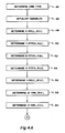
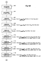
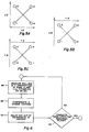
- FIGURES 4A through 4C these are illustrated in flowchart form, the various steps taken by the system of FIGURE 3 in order to calibrate the CMM 10. However, preferably, before the actual calibration procedure is performed, verification of machine function, ranges, axis friction and repeatability is made.
- the individual calibrating the CMM 10 indicates the type of CMM which is being calibrated.
- the CMM 10 illustrated in FIGURE 1 is of a cantilever design.
- data is input into the control system 16 by the operator, such as by typing that information into a keyboard 44 of the computer 20.
- the computer system 20 assists the operator to enter the particular model number, machine serial number and date into the system 20.
- the computer system 20 also instructs the operator to place the end of the probe shaft to machine position 0,0,0.
- the extent of machine axis travel is stored relative to the particular model number.
- the amount of X-roll given by the mathematical symbol, A(x), is determined by using the electronic levels in a conventional fashion along every 50 millimeters of X axes movement with the Y and Z axes of the device 12 locked so that movement only along the X axis is allowed.
- the device 12 is preferably automatically moved under control of the machine control 18 along 50 millimeter intervals on the X axis.
- the MP 36 provides to the computer 34 the exact location in the machine coordinate system at which the measurement was taken. In this way a table of X-roll data as a function of the X position is generated.
- the error, Y-pitch given by the mathematical symbol, A(y), is determined by first attaching an angular reflector for the laser interferometer to the device 12 in place of the CMM probe 14. The X and Z axes of the device 12 are then locked so that only movement along the Y axis is allowed. The laser interferometer is aligned so that the beam travels parallel to the Y axis and strikes the reflector. The reflector moves along the Y axis of the device 12. CMM-generated Y axis readings and the interferometer readings are obtained at every 50 millimeter intervals under control of the machine control 18. In this way, a similar table of data is generated for Y pitch for the entire range of travel of the Y axis.
- the Z-pitch error data, A(z) is determined in much the same fashion as the X roll error data was obtained in block 48.
- the electronic levels are used to obtain the error data along every 50 millimeters of Z axis travel for the entire range of Z axis motion.
- X-pitch error data, P(x) is determined for every 50 millimeters along the X axis by use of the laser angular interferometer to thereby generate the table of error data.
- the Y-roll error data, B(y) is determined with the electronic levels for every 50 millimeters of Y axis movement.
- the Z-yaw error data, B(z) is determined for every 50 millimeters of Z axis movement with the electronic levels.
- X-yaw error data, C(x) is determined for every 50 millimeters of X axis movement with the laser angular interferometer.
- Y-yaw error data, C(y) is determined for every 50 millimeters along the Y axis by utilizing the laser angular interferometer.
- the Z-roll error data, C(z) is determined for every 50 millimeter of Z axis movement utilizing the vertical straight edge, touch probe and probe extensions.
- the data obtained in blocks 48 through 64 are typically measured in arc seconds and are preferably converted into radians before being stored in tabular form so that the data can be used in calculations as will be apparent hereinbelow.
- X-scale error data X(x) is determined for each 25 millimeters of movement along the X axis by use of the laser linear interferometer at some convenient Y, Z position (preferably table level).
- a table of Y-scale error data is generated in a similar fashion as the X-scale error data was generated in step 66 by utilizing readings from the laser linear interferometer taken at 25 millimeter intervals along the entire Y axis.
- the Z-scale error data is computed by utilizing readings from the laser linear interferometer and the CMM-generated Z axis readings to thereby form the tabular Z-scale error data for every 25 millimeters of Z axis movement.
- X-straightness in Y error data Y(x) is determined through the use of the laser straightness interferometer which provides readings along every 50 millimeters of X axis movement at some convenient Z position (preferably table level).
- a least squares, best fit line is fitted to the data points and the distance of the data points from the line is determined, thereby normalizing Y(x) about the best fit line.
- X-straightness in Z error data X-straightness in Z error data
- Y-straightness in X error data Y-straightness in Z error data respectively
- the error data in blocks 74, 76 and 78 are normalized about a best fit line as was done in block 72.
- X(z) is determined along 50 millimeter measurement intervals along the Z axis by utilizing the straight edge and probe. Utilizing the laser straightness interferometer results in limited Z travel. Consequently, the Z-straightness in X error data is a function of the X axis reading from the measurement processor 36, X mp measuring a straight edge with touch probe; and, the product of the Z axis probe offset and the Z-yaw error data for the corresponding Z axis reading, S z ⁇ B(z) and S y ⁇ C(z). Similarly, after the equation adjacent the block 80 has been solved, a least squares, best fit line is fit to the resulting data points and the distance of the data points from the best fit line is computed and thereafter stored in tabular form.
- the X-Y squareness error data, P yx is determined from the solution to the quadratic equation indicated in FIGURE 4C.
- the values for A,B and C of the quadratic equation are given by the first set of equations for A, B and C and are derived in the following fashion.
- step 86 the ball bar is placed in two orientations in the X-Y plane at approximately 90 degrees from each other.
- the centers of the spheres at the ends of the ball bar are computed in order to determine the length of the ball bar in each of the orientations.
- the four sphere centers are compensated by using the previously computed compensation data.
- the length of the ball bar in each of the orientations is equated to each other.
- the X-Y squareness factor becomes a quadratic equation as previously indicated.
- the solution to the quadratic equation determines the X-Y squareness factor, P yx , in radians, as indicated in block 90.
- the X-Z squareness factor P zx of step 94 is then computed.
- the middle set of A, B, and C equations is utilized to solve the quadratic equation to determine the X-Z squareness.
- the ball bar is placed in two different orientations in the X-Z plane and blocks 86, 88, 90 and 92 are repeated.
- the Y-Z squareness factor, P zy is computed in the same fashion by placing the ball bar in two different orientations in the Z-Y plane as indicated in FIGURE 5C.
- the lowermost set of A, B and C equations is utilized in order to solve the quadratic equation to determine the Y-Z squareness factor.
- calibration sphere coordinates are determined by first mounting the touch probe 14 at a known distal end of the probe shaft 22.
- a calibration sphere 100 is screwed into the worktable 26 at a preselected location within the measuring volume 102 of the device 12.
- the positioning device 12 is then moved so that the probe 14 touches the sphere 100 at a number of different points.
- Sphere coordinates are determined by vector addition of vectors B and C wherein vector A equals vector B plus vector C as indicated in FIGURE 7A.
- the data is then stored on the backup disc 38.
- the data is also down-loaded to memory 110 within the measurement processor 36 which is utilized by the measurement processor 36 during operation of the CMM 10 to compensate the CMM 10 for the entire measuring volume 102 thereof.
- FIGURE 8 there is illustrated a method and system for utilizing the previously stored, factory calibrated machine characteristics of error data in order to determine the absolute position of a point in the measuring volume 102 of the device 12.
- the factory calibrated machine characteristics stored within the measurement processor 36 characterizes the motion of the X, Y and Z axes in terms of its deviation from a theoretically true axis system.
- Block 110 represents the memory of the MP 36 in which the factory-calibrated machine characteristics or axis correction data are stored in tabular form.
- the measurement processor 36 determines the machine characteristics for current sensor readings by capturing the actual position information from each machine axis sensor and uses this to locate information in the tables describing the machine characteristics in that particular position.
- the measurement processor 36 mathematically combines machine feedback or position sensor signal and the characteristic axis correction data to produce a corrected set of coordinate values which describes the position of the probe 14 in a true Cartesian coordinate system.
- the corrected X readout signal is a function of: the uncorrected value of the X readout, X mp ; the X scale error data for the particular value of X, X(x); Z-straightness in X error data, X(z); Y-straightness in X error data, X(y); the product of corresponding value of Z and the sum of the X-pitch error data, the Y-roll error data and the Z-Y squareness factor, Z[B(x) + B(y) + P zx ] ; the product of the uncorrected Y value and the sum of the Y-yaw error data and the X-Y squareness factor, Y[C(x) + P yx ] ; the product of the Z component of the probe offset and the sum of the X-pitch error data, the Y-roll error data
- the advantages accruing to the use of the present invention are numerous. For example, a more accurate CMM can be obtained at lower cost. Also, the system eliminates many manhours of final machine assembly in fine tuning the machine mechanically for accuracy as well as allowing increased manufacturing tolerances for many individual components of the CMM.
Landscapes
- Physics & Mathematics (AREA)
- General Physics & Mathematics (AREA)
- Length Measuring Devices With Unspecified Measuring Means (AREA)
- A Measuring Device Byusing Mechanical Method (AREA)
Claims (10)
- Verfahren zum Bestimmen der Absolutposition eines Punktes im Meßvolumen (102) einer CMM (10) (Koordinatenmeßmaschine) mit einem Fühlerschaft (22) und einem an einem distalen Ende dieses Fühlerschaftes gehaltenen Fühler (14), wobei der Fühler drei Bewegungsachsen (X, Y, Z) aufweist, und wobei die CMM Einrichtungen zum Liefern eines Positionssignals durch Feststellen der Position des Fühlers für jede der Bewegungsachsen im Koordinatensystem der CMM umfaßt sowie Steuerungsmittel (36) zum Aufnehmen der Positionssignale und zum Liefern eines Koordinatenmeßsignals, welches die Position des Fühlers angibt, wobei das Verfahren in einem Kalibriervorgang vor dem eigentlichen Einsatz der CMM die Schritte umfaßt, Geometriefehler der CMM zu messen und Fehlerdaten zum Kompensieren von CMM-Geometriefehlern für den Verfahrweg jeder der Achsen zu speichern, sowie die Schritte, gespeicherte Fehlerdaten für eine gegebene Position des Fühlerschaftes relativ zu jeder der Bewegungsachsen als Funktion der Positionssignale zu bestimmen, um korrigierte Positionsdaten zu berechnen, dadurch gekennzeichnet, daß der Meßschritt das Messen von Fühlerfehlstellungsdaten (98) mittels eines auf einem Arbeitstisch der CMM montierten Meßkörpers umfaßt; daß der Speicherschritt das Berechnen von Achskorrekturdaten aus den Achsfehlerdaten und zugeordneten Positionssignalen umfaßt sowie das Speichern (108) von Sätzen von Achskorrekturdaten in Speichereinrichtungen eines in der Steuerung vorgesehenen Meßprozessors, sowie das Speichern der Fühlerfehlstellungsdaten in der Speichereinrichtung des Meßprozessors; daß der Bestimmungsschritt das Bestimmen (112) eines Subsatzes der Achskorrekturdaten für eine gegebene Position des Fühlerschaftes relativ zu jeder der Bewegungsachsen als Funktion der Positionssignale sowie das Bestimmen von Fühlerfehlstellungsdaten umfaßt; und daß ein Schritt vorgesehen ist, die Positionssignale mit dem Subsatz der Achskorrekturdaten zu kombinieren sowie die Fühlerfehlstellungsdaten mit den Positionssignalen und dem Subsatz der Achskorrekturdaten zu kombinieren, um ein korrigiertes Positionssignal im Standard-Koordinatensystem zu erhalten.
- Verfahren nach Anspruch 1, dadurch gekennzeichnet, daß der Bestimmungsschritt das Bestimmen kompensierter Rotationsdaten (48 - 64) umfaßt, welche den Betrag einer Winkeldrehung um jede der Achsen für jede dieser Achsen repräsentieren; ferner das Bestimmen von Rechtwinkligkeitsdaten (84, 94, 96), welche die Orthogonalität dreier unterschiedlicher Achsenpaare repräsentieren; ferner das Bestimmen normalisierter Geradlinigkeitsdaten (72 - 82) für jede dieser Achsen in bezug auf jede der anderen Achsen; und Skalenfehlerdaten (66, 68, 70), welche Fehler in jeder der Einrichtungen repräsentieren und wobei das Verfahren ferner folgende Schritte umfaßt:
Messen der Position eines Meßkörpers mittels der CMM durch Verfahren des Fühlers der CMM derart, daß jede der Einrichtungen ein Meßkörper-Positionssignal liefert und der Meßprozessor ein entsprechendes Meßsignal als Funktion der Meßkörper-Positionssignale liefert;
Berechnen von Fühlerfehlstellungsdaten (98) als Funktion der gemessenen Position des Meßkörpers, wobei die Fühlerfehlstellungsdaten die Fehlstellung des Fühlers gegenüber dem Fühlerschaft entlang jeder der Achsen repräsentiert;
Speichern der Fühlerfehlstellungsdaten in den Speichereinrichtungen des Meßprozessors;
Entnehmen der Fühlerfehlstellungsdaten aus der Speichereinrichtung;
Bestimmen kompensierter Fühlerfehlstellungsdaten als Funktion der Fühlerfehlstellungsdaten und ihrer jeweiligen kompensierten Rotationsdaten; und Modifizieren (114) der von den Einrichtungen gelieferten Positionssignale als Funktion der kompensierten Fühlerfehlstellungsdaten und dem Subsatz von Achskorrekturdaten einschließlich der kompensierten Rotationsdaten, der Rechtwinkligkeitsdaten, der normalisierten Geradlinigkeitsdaten und der Skalenfehlerdaten, wobei der Modifizierschritt unmittelbar nach dem Bestimmen (112) des Subsatzes von Achskorrekturdaten durchgeführt wird, um ein korrigiertes Positionssignal in einem Standard-Koordinatensystem zu erhalten. - Verfahren nach Anspruch 1 oder 2, wobei das korrigierte Positionssignal eine Komponente hat, die eine korrigierte Position entlang jeder der Achsen repräsentiert und wobei jede dieser Komponenten eine Funktion (Figur 9) des Produktes aus den jeweiligen kompensierten Rotationsdaten und dem Positionssignal einer der anderen Achsen ist.
- Verfahren nach Anspruch 3, dadurch gekennzeichnet, daß wenigsten eine dieser Komponenten eine Funktion (Figur 9) des Produktes ihrer jeweiligen Rechtwinkligkeitsdaten und des Positionssignals einer oder der anderen Achsen ist.
- Verfahren nach Anspruch 3 oder 4, wobei wenigstens eine dieser Komponenten eine Funktion der normalisierten Geradlinigkeitsdaten ihrer jeweiligen Achse ist.
- Verfahren nach den Ansprüchen 3 bis 5, wobei wenigstens eine der Komponenten eine Funktion der Skalenfehlerdaten für ihre jeweilige Achse ist.
- Verfahren nach einem der Ansprüche 1 bis 5, wobei der Meßkörper eine Kalibrierkugel (100) umfaßt und wobei der Meßschritt den Schritt umfaßt, den Fühler an mehrere Positionen der Kugel anzulegen.
- Vorrichtung zum Bestimmen der absoluten Position eines Punktes in einem Meßvolumen (102) einer CMM (10) mit einem Fühlerschaft (22) und einer an einem distalen Ende des Fühlerschaftes gehaltenen Fühler (14), wobei der Fühler drei Bewegungsachsen (X, Y, Z) hat, wobei ferner die CMM Einrichtungen zum Liefern eines Positionssignals durch Bestimmen der Position des Fühlers für jede der Bewegungsachsen im Koordinatensystem der CMM hat sowie eine Steuerungseinrichtung (36) zum Aufnehmen jedes der Positionssignale und zum Liefern eines Koordinatenmeßsignals, welches die Position des Fühlers angibt, wobei die Einrichtung eine Speichereinrichtung (110) zum Speichern von Fehlerdaten für die Kompensierung von CMM-Geometriefehlern für den Verfahrweg entlang jeder der Achsen hat, ferner Mittel (36 und 112) zum Bestimmen gespeicherter Fehlerdaten für eine gegebene Position des Fühlerschaftes relativ zu jeder der Bewegungsachsen als Funktion der Positionssignale, dadurch gekennzeichnet, daß
die Speichereinrichtung (110) so ausgelegt ist, daß sie Sätze von Achskorrekturdaten speichern kann, die man aus den gemessenen Achsfehlerdaten und den jeweiligen Positionssignalen erhält, sowie von Fühlerfehlstellungsdaten, die man in einem Kalibiervorgang vor dem eigentlichen Einsatz der CMM ermittelt;
daß die Bestimmungsmittel (36, 112) so ausgelegt sind, daß sie einen Subsatz der Achskorrekturdaten für eine gegebene Position des Fühlerschaftes relativ zu jeder der Bewegungsachsen (X, Y, Z) als Funktion der Positionssignale bestimmen kann und daß sie die jeweiligen Fühlerfehlstellungsdaten bestimmen kann;
und daß die Steuerungseinrichtung (114, 36) so ausgelegt ist, daß sie die Positionssignale mit dem Subsatz von Achsfehlerdaten und den Fühlerfehlstellungsdaten kombinieren kann, um ein korrigiertes Positionssignal im Standard-Koordinatensystem zu erhalten, die Korrekturdaten zu speichern und korrigierte Positionssignale aus den gegebenen Positionsdaten und den zugeordneten, gespeicherten Korrekturdaten zu berechnen. - Einrichtung nach Anspruch 8, dadurch gekennzeichnet, daß die Bestimmungsmittel kompensierte Rotationsdaten (48 - 64) bestimmen, welche den Betrag einer Winkelverdrehung um jede der Achsen für jeder dieser Achsen repräsentieren; ferner Rechtwinkligkeitsdaten (84, 94, 96), welche die Orthogonalität der drei unterschiedlichen Achsenpaare repräsentieren; ferner normalisierte Geradlinigkeitsdaten (72 - 82) für jede dieser Achsen mit Bezug auf jede der anderen Achsen; und Skalenfehlerdaten (66, 68; 70), welche Fehler in jeder der Einrichtungen repräsentieren; daß jede der Einrichtungen ein Meßkörper-Positionssignal beim Verfahren des Fühlers der CMM zu dem Meßkörper liefert;
daß die Steuerungseinrichtung der CMM einen Meßprozessor umfaßt, welcher ein entsprechendes Meßsignal als Funktion der Meßkörper-Positionssignale liefert; und
daß ein Rechner zum Berechnen von Fühlerfehlstellungsdaten als Funktion der gemessenen Position des Meßkörpers vorgesehen ist, wobei die Fühlerfehlstellungsdaten die Fehlstellung des Fühlers gegenüber dem Fühlerschaft entlang jeder der Achsen repräsentieren; wobei die Speichereinrichtung die Fühlerfehlstellungsdaten speichert; und wobei der Meßprozessor kompensierte Fühlerfehlstellungsdaten als Funktion der Fühlerfehlstellungsdaten und ihrer jeweiligen kompensierten Rotationsdaten bestimmt und der Meßprozessor die von den Einrichtungen kommenden Positionssignale als Funktion der kompensierten Fühlerfehlstellungsdaten und des Subsatzes von Achskorrekturdaten einschließlich der kompensierten Rotationsdaten, der Rechtwinkligkeitsdaten, der normalisierten Geradlinigkeitsdaten und der Skalenfehlerdaten modifiziert, um ein korrigiertes Positionssignal in einem Standard-Koordinatensystem zu erhalten. - Einrichtung nach Anspruch 8 oder 9, wobei der Meßkörper eine Kalibrierkugel (100) umfaßt.
Applications Claiming Priority (2)
| Application Number | Priority Date | Filing Date | Title |
|---|---|---|---|
| US443587A | 1987-01-20 | 1987-01-20 | |
| US4435 | 1987-01-20 |
Publications (2)
| Publication Number | Publication Date |
|---|---|
| EP0279926A1 EP0279926A1 (de) | 1988-08-31 |
| EP0279926B1 true EP0279926B1 (de) | 1992-09-09 |
Family
ID=21710793
Family Applications (1)
| Application Number | Title | Priority Date | Filing Date |
|---|---|---|---|
| EP19870117850 Expired EP0279926B1 (de) | 1987-01-20 | 1987-12-02 | Positionsbestimmungsverfahren innerhalb des Messraumes eines Koordinatenmessgerätes und dergleichen und System dafür |
Country Status (4)
| Country | Link |
|---|---|
| EP (1) | EP0279926B1 (de) |
| JP (1) | JPS63302310A (de) |
| CA (1) | CA1310092C (de) |
| DE (1) | DE3781674T2 (de) |
Families Citing this family (13)
| Publication number | Priority date | Publication date | Assignee | Title |
|---|---|---|---|---|
| DE3833779A1 (de) * | 1988-10-05 | 1990-04-12 | Mauser Werke Oberndorf | Mehrkoordinaten-messmaschine |
| US5209131A (en) * | 1989-11-03 | 1993-05-11 | Rank Taylor Hobson | Metrology |
| DE4434014A1 (de) | 1994-09-23 | 1996-03-28 | Zeiss Carl Fa | Verfahren zur Kalibrierung eines Koordinatenmeßgerätes mit zwei rotatorischen Achsen |
| GB2350429B (en) | 1999-05-28 | 2003-11-12 | Taylor Hobson Ltd | A metrological instrument |
| JP4705792B2 (ja) * | 2005-03-17 | 2011-06-22 | 株式会社ミツトヨ | 軸間角度補正方法 |
| JP5183884B2 (ja) * | 2006-05-08 | 2013-04-17 | 株式会社ミツトヨ | 補正方法、及び測定装置 |
| EP2042829B2 (de) * | 2007-09-26 | 2017-08-09 | Hexagon Metrology AB | Modulare Kalibrierung |
| EP2068114A1 (de) * | 2007-12-04 | 2009-06-10 | Metris IPR N.V. | Objektmessungsgerät mit optimiertem Kalibrierungssystem |
| DE202008005750U1 (de) * | 2008-04-25 | 2008-07-10 | Dmg Microset Gmbh | Vorrichtung zur Vermessung und/oder Einstellung eines Werkzeugs |
| DE102018208189B4 (de) * | 2018-05-24 | 2021-05-20 | Carl Zeiss Industrielle Messtechnik Gmbh | Verfahren und Vorrichtung zum Ermitteln der Torsionsfehler einer Maschinenachse |
| CN112629456B (zh) * | 2020-11-17 | 2022-11-08 | 中国航发哈尔滨东安发动机有限公司 | 涡轴发动机零部件复杂曲面自动测量系统及测量方法 |
| CN114252053B (zh) * | 2021-12-30 | 2024-04-05 | 中国矿业大学 | 一种变长度测斜仪探头 |
| CN116890164A (zh) * | 2023-03-16 | 2023-10-17 | 浙江天弘激光科技有限公司 | 转子、定子的自动焊接、检测、清洗、防锈一体生产工艺 |
Family Cites Families (6)
| Publication number | Priority date | Publication date | Assignee | Title |
|---|---|---|---|---|
| US3555254A (en) * | 1967-04-17 | 1971-01-12 | Gerber Scientific Instr Co | Error correcting system and method for use with plotters, machine tools and the like |
| DE2739527C2 (de) * | 1977-09-02 | 1979-04-19 | Karl Juergen Dipl.-Ing. 6100 Darmstadt Lenz | Verfahren und Einrichtung zur Bestimmung der Fehler von mit mehrachsigen Meßeinrichtungen versehenen Werkzeugmaschinen und Meßmaschinen |
| GB2042719B (en) * | 1978-12-27 | 1983-03-09 | Ferranti Ltd | Positional measuring apparatus |
| US4462082A (en) | 1981-09-17 | 1984-07-24 | Rockwell International Corporation | Automatic calibration system for ultrasonic inspection |
| US4437151A (en) | 1982-04-16 | 1984-03-13 | Deere & Company | Coordinate measuring machine inspection and adjustment method |
| GB8420096D0 (en) * | 1984-08-07 | 1984-09-12 | Putra Siregar N I | Measurement of errors |
-
1987
- 1987-12-02 DE DE19873781674 patent/DE3781674T2/de not_active Revoked
- 1987-12-02 EP EP19870117850 patent/EP0279926B1/de not_active Expired
- 1987-12-21 CA CA000554958A patent/CA1310092C/en not_active Expired - Fee Related
-
1988
- 1988-01-20 JP JP857488A patent/JPS63302310A/ja active Pending
Also Published As
| Publication number | Publication date |
|---|---|
| EP0279926A1 (de) | 1988-08-31 |
| CA1310092C (en) | 1992-11-10 |
| JPS63302310A (ja) | 1988-12-09 |
| DE3781674T2 (de) | 1993-04-15 |
| DE3781674D1 (de) | 1992-10-15 |
Similar Documents
| Publication | Publication Date | Title |
|---|---|---|
| US4945501A (en) | Method for determining position within the measuring volume of a coordinate measuring machine and the like and system therefor | |
| EP0275428B2 (de) | Kalibrierungsverfahren für ein Koordinatenmessgerät und ähnliche Geräte | |
| US4982504A (en) | Method for determining positional errors and for compensating for such errors, and apparatus for carrying out the method | |
| US4663852A (en) | Active error compensation in a coordinated measuring machine | |
| KR101158772B1 (ko) | 수치제어 공작기계 및 수치제어 장치 | |
| JP4275632B2 (ja) | パラレルメカニズム機構のキャリブレーション方法、キャリブレーションの検証方法、キャリブレーションの検証プログラム、データ採取方法及び空間位置補正における補正データ採取方法 | |
| EP1579168B2 (de) | Werkstückinspektionsverfahren und vorrichtung | |
| US6701268B2 (en) | Method for calibrating scanning probe and computer-readable medium therefor | |
| US5313410A (en) | Artifact and method for verifying accuracy of a positioning apparatus | |
| US20030167103A1 (en) | Robot machining tool position and orientation calibration | |
| US4782598A (en) | Active error compensation in a coordinate measuring machine | |
| CA1310092C (en) | Method for determining position within the measuring volume of a coordinate measuring machine and the like and system therefor | |
| WO2000014474A1 (en) | Coordinate measuring machine having a machine tool frame | |
| US6701267B2 (en) | Method for calibrating probe and computer-readable medium | |
| EP4193119B1 (de) | Messverfahren | |
| Breitzke et al. | Workshop-suited geometric errors identification of three-axis machine tools using on-machine measurement for long term precision assurance | |
| EP2050534B1 (de) | Verfahren zum Prüfen einer Rotationsachse mit einer selbstzentrierenden Messvorrichtung | |
| US10222193B2 (en) | Method and apparatus for inspecting workpieces | |
| US5220510A (en) | Coordinate system correcting apparatus for machine tool | |
| Pahk et al. | Application of microcomputer for assessing the probe lobing error and geometric errors of CMMs using commercial ring gauges | |
| Liu et al. | The application of the double-readheads planar encoder system for error calibration of computer numerical control machine tools | |
| JPS63251810A (ja) | 水平多関節ロボツトの較正装置 | |
| Tittagala | The role of coordinate measuring machines in CAM | |
| De et al. | for Three Dimensional Coordinate Measuring |
Legal Events
| Date | Code | Title | Description |
|---|---|---|---|
| PUAI | Public reference made under article 153(3) epc to a published international application that has entered the european phase |
Free format text: ORIGINAL CODE: 0009012 |
|
| AK | Designated contracting states |
Kind code of ref document: A1 Designated state(s): AT BE CH DE ES FR GB GR IT LI LU NL SE |
|
| RBV | Designated contracting states (corrected) |
Designated state(s): DE FR GB IT |
|
| 17P | Request for examination filed |
Effective date: 19890228 |
|
| 17Q | First examination report despatched |
Effective date: 19890901 |
|
| GRAA | (expected) grant |
Free format text: ORIGINAL CODE: 0009210 |
|
| AK | Designated contracting states |
Kind code of ref document: B1 Designated state(s): DE FR GB IT |
|
| REF | Corresponds to: |
Ref document number: 3781674 Country of ref document: DE Date of ref document: 19921015 |
|
| ITF | It: translation for a ep patent filed | ||
| ET | Fr: translation filed | ||
| PLBI | Opposition filed |
Free format text: ORIGINAL CODE: 0009260 |
|
| 26 | Opposition filed |
Opponent name: FIRMA CARL ZEISS Effective date: 19930604 |
|
| PGFP | Annual fee paid to national office [announced via postgrant information from national office to epo] |
Ref country code: GB Payment date: 19941111 Year of fee payment: 8 |
|
| PGFP | Annual fee paid to national office [announced via postgrant information from national office to epo] |
Ref country code: FR Payment date: 19941209 Year of fee payment: 8 |
|
| PGFP | Annual fee paid to national office [announced via postgrant information from national office to epo] |
Ref country code: DE Payment date: 19941223 Year of fee payment: 8 |
|
| RDAG | Patent revoked |
Free format text: ORIGINAL CODE: 0009271 |
|
| STAA | Information on the status of an ep patent application or granted ep patent |
Free format text: STATUS: PATENT REVOKED |
|
| 27W | Patent revoked |
Effective date: 19950321 |
|
| GBPR | Gb: patent revoked under art. 102 of the ep convention designating the uk as contracting state |
Free format text: 950321 |
|
| APAH | Appeal reference modified |
Free format text: ORIGINAL CODE: EPIDOSCREFNO |