EP0279992A2 - Buse à démontage rapide avec embout de pulvérisation à emmanchement du type à baillonnette - Google Patents
Buse à démontage rapide avec embout de pulvérisation à emmanchement du type à baillonnette Download PDFInfo
- Publication number
- EP0279992A2 EP0279992A2 EP87311348A EP87311348A EP0279992A2 EP 0279992 A2 EP0279992 A2 EP 0279992A2 EP 87311348 A EP87311348 A EP 87311348A EP 87311348 A EP87311348 A EP 87311348A EP 0279992 A2 EP0279992 A2 EP 0279992A2
- Authority
- EP
- European Patent Office
- Prior art keywords
- nozzle
- tip
- socket
- lugs
- nozzle assembly
- Prior art date
- Legal status (The legal status is an assumption and is not a legal conclusion. Google has not performed a legal analysis and makes no representation as to the accuracy of the status listed.)
- Granted
Links
Images

Classifications
-
- B—PERFORMING OPERATIONS; TRANSPORTING
- B05—SPRAYING OR ATOMISING IN GENERAL; APPLYING FLUENT MATERIALS TO SURFACES, IN GENERAL
- B05B—SPRAYING APPARATUS; ATOMISING APPARATUS; NOZZLES
- B05B1/00—Nozzles, spray heads or other outlets, with or without auxiliary devices such as valves, heating means
-
- F—MECHANICAL ENGINEERING; LIGHTING; HEATING; WEAPONS; BLASTING
- F16—ENGINEERING ELEMENTS AND UNITS; GENERAL MEASURES FOR PRODUCING AND MAINTAINING EFFECTIVE FUNCTIONING OF MACHINES OR INSTALLATIONS; THERMAL INSULATION IN GENERAL
- F16L—PIPES; JOINTS OR FITTINGS FOR PIPES; SUPPORTS FOR PIPES, CABLES OR PROTECTIVE TUBING; MEANS FOR THERMAL INSULATION IN GENERAL
- F16L37/00—Couplings of the quick-acting type
- F16L37/24—Couplings of the quick-acting type in which the connection is made by inserting one member axially into the other and rotating it to a limited extent, e.g. with bayonet-action
- F16L37/244—Couplings of the quick-acting type in which the connection is made by inserting one member axially into the other and rotating it to a limited extent, e.g. with bayonet-action the coupling being co-axial with the pipe
- F16L37/248—Bayonet-type couplings
-
- B—PERFORMING OPERATIONS; TRANSPORTING
- B05—SPRAYING OR ATOMISING IN GENERAL; APPLYING FLUENT MATERIALS TO SURFACES, IN GENERAL
- B05B—SPRAYING APPARATUS; ATOMISING APPARATUS; NOZZLES
- B05B1/00—Nozzles, spray heads or other outlets, with or without auxiliary devices such as valves, heating means
- B05B1/34—Nozzles, spray heads or other outlets, with or without auxiliary devices such as valves, heating means designed to influence the nature of flow of the liquid or other fluent material, e.g. to produce swirl
- B05B1/3405—Nozzles, spray heads or other outlets, with or without auxiliary devices such as valves, heating means designed to influence the nature of flow of the liquid or other fluent material, e.g. to produce swirl to produce swirl
- B05B1/341—Nozzles, spray heads or other outlets, with or without auxiliary devices such as valves, heating means designed to influence the nature of flow of the liquid or other fluent material, e.g. to produce swirl to produce swirl before discharging the liquid or other fluent material, e.g. in a swirl chamber upstream the spray outlet
- B05B1/3415—Nozzles, spray heads or other outlets, with or without auxiliary devices such as valves, heating means designed to influence the nature of flow of the liquid or other fluent material, e.g. to produce swirl to produce swirl before discharging the liquid or other fluent material, e.g. in a swirl chamber upstream the spray outlet with swirl imparting inserts upstream of the swirl chamber
-
- B—PERFORMING OPERATIONS; TRANSPORTING
- B05—SPRAYING OR ATOMISING IN GENERAL; APPLYING FLUENT MATERIALS TO SURFACES, IN GENERAL
- B05B—SPRAYING APPARATUS; ATOMISING APPARATUS; NOZZLES
- B05B15/00—Details of spraying plant or spraying apparatus not otherwise provided for; Accessories
- B05B15/60—Arrangements for mounting, supporting or holding spraying apparatus
- B05B15/65—Mounting arrangements for fluid connection of the spraying apparatus or its outlets to flow conduits
Definitions
- the present invention relates generally to spray nozzle assemblies, and more particularly, concerns spray nozzle assemblies of a type which have quick disconnect means for permitting disassembly of the nozzle for replacement of the nozzle tip or for cleaning.
- nozzle tip It is often necessary to remove and/or change the tip of a spray nozzle for various reasons, such as inspection of the parts and cleaning if required because of stoppage, or clogging, or any other type of blockage.
- the nozzle tip may be replaced, or a different type substituted for a different type of spraying operation.
- the usual threaded type connection utilized with spraying apparatus between a nozzle body and a spraying tip is subject to obvious limitations.
- the threaded connection requires adjustment of the direction each time the nozzle is removed.
- Some spraying apparatus is not stationary and this requires that tools be provided at all of the various locations where the apparatus may be used, or otherwise transported with the apparatus to the site. Just the operation of removing and reapplying a threaded connection is unduly time-consuming, especially where the spraying apparatus may have multiple nozzles.
- Some quick disconnect nozzles relied upon frictional engagement of the spray tip with the nozzle body and this necessitated very precise machining, or molding tolerances in the manufacture of such parts. This type of engagement was also undesirable for non-axial spraying directions inasmuch as the spray tip had to be adjusted for the proper direction each time such nozzles were assembled, or disassembled.
- U.S. Pat. No. 4,438,884 discloses a quick disconnect spray nozzle comprised of a spray tip and a nozzle body and a combination seal and pressure exerting member between the body and the nozzle tip.
- the combination pressure exerting seal member is resilient and is mounted in the nozzle body concentric with the nozzle bore and when the nozzle tip is mounted in the body, a sealing ring on the tip abuts an end of the seal member around the bore, thus providing a seal between the parts and also compressing the seal member, whereby pressure is applied between the nozzle body and the tip to maintain the locked condition of the tip in the body.
- the combination member thus eliminates any need for a separate spring and a separate sealing member and the single member functions both as a seal and as a spring, or pressure-exerting member, to provide substantial advantages over earlier nozzles using the separate spring and separate seal.
- the present sealing member acts also to seal the assembly against the entry of contaminants such as sand or other abrasive materials between the tip and the body housing which would cause excessive wear and possibly destroy the sealing properties of the seal member.
- Quick disconnect nozzles of the type shown in u.S. Pat. No. 4,438,884, assigned to the same assignee as the present application, are commonly used for agricultural purposes. Large numbers of such nozzles are mounted on a common spray boom. Such nozzle assemblies may also have a spray tip retaining cap which is positioned onto a nozzle body. A sealing member interposed between the cap and body serves to provide a fluid-tight seal between the two members and to bias the cap in its assembled condition. In assembling the cap, it is commonly necessary to force the cap against the biasing force of the sealing member and then twist the cap into an assembled or locked position. Because of the location of the nozzles on the boom, and the multiplicity of such nozzles, it can be cumbersome, difficult, and tiresome to disconnect and reassemble large numbers of such nozzles.
- Another object is to provide a spray nozzle assembly as characterized above which permits a spray tip to be removed and replaced with a simple twisting action, and without the necessity for exerting manual axial force to overcome the force of biasing springs, seals of the like.
- a further object is to provide a quick disconnect nozzle of the above kind which is adapted for easy replacement of the spray tip in predetermined angular relation to the nozzle body.
- a related object is to provide such a spray nozzle assembly with means for positively locating the spray tip in predetermined angular position relative to the nozzle body upon replacement, and for preventing twisting of the spray tip or holding cap beyond such location.
- Still another object is to provide a quick disconnect spray nozzle assembly of the above kind in which the nozzle may be flushed following removal of the spray tip and cap without unwanted dislodging or discharge of the sealing and biasing member.
- Yet another object is to provide a spray nozzle assembly of the foregoing type which includes a whirl imparting vane that is easily removable and replaceable during cleaning of the nozzle assembly.
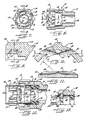
- the nozzle assembly includes a nozzle body 10, a combination seal and pressure exerting member 20, a spray nozzle tip 30, and an optional swirl imparting vane 40.
- the nozzle body 10 is threaded at 11 for connection to a suitable source of spray fluid and a hexagonal portion 12 enables a suitable wrench to be applied to tighten this connection, as required.
- the exterior of the body 10 also is provided with a plurality of longitudinally extending ribs 13 which facilitate tightening and loosening the nozzle body 10 from its fluid source connection by hand.
- the interior of the nozzle body is provided with a fluid passageway defined by a stepped, internal bore having a reduced fluid flow portion 14, a radial shoulder or seat 15 and an enlarged annular chamber 16 for receiving the combination seal and pressure exerting member 30.
- the nozzle body is provided with an annular, axially extending lip 17 at the juncture of the flow passageway portion 14 and the seal seat 15.
- the combination seal and pressure exerting member 20 is generally tubular in shape and is made of a suitable chemical resistant elastomeric material. As illustrated, the seal has a somewhat reduced outer diameter midway between its ends and the somewhat larger outer diameter of the end portions are dimensional to provide a snug fit within the annular chamber 16 of the nozzle body 10.
- the inner diameter the sealing member 20 is slightly larger than the diameter of the fluid passage portion 14 and the upstream end of the seal member 20 engages the seat 15 radially outwardly of the outer face of the axially extending lip 17.
- the combination of the snug fit of the seal member 20 in the chamber 16, the engagement with the seat outwardly of the lip 17 and the enlarged inner diameter of the seal with respect to the fluid passage portion 14 cooperate in such a way as to diminish the tendency of fluid flow through the passageway such as during flushing or cleaning to eject the seal member 20 from the chamber 16 even if the spray tip 30 has been removed from the nozzle body 10.
- the spray tip 30 includes an external protective shell 31 which extends axially from a connecting base 32 and surrounds an inner conduit portion 33 defining a stepped internal bore having an enlarged chamber 34, an intermediate flow passage 35 and a smaller spray orifice 36.
- the spray orifice 36 is provided with a diverging outlet end 38 which produces a generally conical spray pattern as schematically indicated by dash lines in Fig. 1.
- the spray nozzle assembly includes a swirl imparting vane 40 in the chamber 34 which facilitates final mixing of the spray fluid in the passage 35 and also generates a uniform discharge through the orifice 36.
- the swirl vane 40 includes an upstream flow divider web 41 and a pair of integrally formed semi-helical deflectors 42 located downstream thereof. It will be understood that the deflectors 42 impart a swirl-like motion to the spray fluid causing it to rotate in a clockwise direction, as seen looking in the downstream direction.
- the chamber 34 is preferably formed with a pair of diametrically opposed arcuate lips 44 at the upstream end thereof.
- Each lip 44 may extend from about 90° to 120° around the circumference of the chamber and due to the helical configuration of the deflectors 42, the swirl vane may be simply screwed into the chamber 34 as the deflectors 42 engage and move past the ends of the lips 44 as the vane is literally screwed into the chamber 34.
- the nozzle body 10 and nozzle tip 30 are provided with cooperating camming surfaces for securely locking the tip in the body in proper angular orientation and without requiring the exertion of substantial axial pressure on the tip to insert and rotatably connect the tip to the body.
- the nozzle tip 30 may be simply inserted into the nozzle body 10 and rotated by hand to effectuate a properly oriented and fluid tight connection.
- it is desirably provided with a plurality of longitudinally extending ribs 37 on the outer protective shell 31, which may be conveniently gripped between the installers finger and thumb.
- each locking lug 51 includes a radially extending, generally triangular flat portion 52 and a pair of generally helically curved sloping ramps 53 and 54 extending outward from the legs 55, 56 of the triangular portion 52 and extend in chord-like fashion to the outer surface of the socket 50.
- each of the sloping ramps 53, 54 is formed on a surface generated by moving a line l tangent to a circle c having a radius r from the nozzle body axis as the tangent line is swept, for example clockwise as seen in Fig. 10, from a first position coinciding with one leg 55 of the triangle 52 to a chordal position d as the line is maintained tangent to the circle.
- the base 32 of the nozzle 30 is provided with a pair of radially extending, diametrically opposed shoulders 60, each of which defines a cam recess 61 having a triangular base 62 joined to sloping cam surfaces 63 and 64, which are generated in the same fashion as the cam surfaces 53 and 54 and thus are complementary thereto and provide essentially surface-to-surface contact when they are respectively engaged. (See Figs. 12 and 13.)
- the base 32 of the nozzle 30 is formed with opposed flats 67 and 68 dimensioned for insertion between the chord-like locking lugs 51 in the nozzle base.
- the nozzle tip can only be inserted in the socket 50 of the nozzle body 10 in one or the other of two angular positions 180° apart. After the tip is so inserted, from the position shown in Fig. 3, it is rotated in the direction of the arrows A.
- the shoulders 60 of the nozzle tip 30 are each provided with sloping lead ramps 69 which engage the sloping cam surfaces 53 of the locking lugs 51 as the nozzle tip 30 is manually rotated. This causes the base 32 of the nozzle tip 30 to move axially into the socket 50 and the cooperating cam surfaces 53, 54 and 63, 64 to mate with one another.
- nozzle tip 30 is cammed axially into the socket 50 by engagement of the cooperating cam surfaces on the socket lugs 51 and the base shoulders 60, the upstream end of the nozzle tip 30 is pressed against the resilient seal member 20.
- nozzle tip 30 is formed with an axially extending, annular sealing bead 71 which engages and seals tightly against the downstream end of the sealing member.
- the base 32 of the nozzle tip 30 is provided with a pair of radially extending stops 73 which limit the rotation of the tip 30 in the socket 50 by coming into engagement with a pair of abutments 74 located in the base of the socket 50.
- the seated portion of the nozzle tip 30 in the socket 50 can be precisely and positively determined. This is particularly desirable in those instances where the nozzle orifice 36 is not axially directed and it is desired to insure that the spray is properly directed when the nozzle tip is installed.
- the nozzle tip 30 can be made without the stops 73 (or the stops can be removed) to permit rotation of the tip 30 in either the clockwise or counterclockwise direction after insertion into the socket 50 of the nozzle body.
- the shoulders 60 on the nozzle base 32 are provided with a second pair of lead ramps 79 which first engage the locking lugs 51 in the socket 50 when the nozzle tip is inserted and rotated in a counterclockwise direction.
- the shapes of the complementary cam surfaces on the tip shoulders 60 and socket lugs 51 provide a self-centering action when the cam surfaces are fully engaged. This insures proper orientation of the nozzle tip 30 even if the shoulder steps 73 are eliminated or removed.
- the nozzle body 10 and nozzle tip 30 are both made of a chemical resistant plastic material such as polyvinylidene fluoride (PVDF) which may be injection-molded in high capacity production equipment.
- PVDF polyvinylidene fluoride
- the nozzle body is designed with a plurality of openings 81 which permit the use of reciprocally mounted side action core members in the injection molding die cavity. It will be understood that after the nozzle body 10 is molded, the sliding core members are retracted so that the nozzle body can be ejected from the mold cavity.
Landscapes
- Engineering & Computer Science (AREA)
- General Engineering & Computer Science (AREA)
- Mechanical Engineering (AREA)
- Nozzles (AREA)
- Mutual Connection Of Rods And Tubes (AREA)
- Details Or Accessories Of Spraying Plant Or Apparatus (AREA)
- Reciprocating Pumps (AREA)
- Catching Or Destruction (AREA)
- Containers And Packaging Bodies Having A Special Means To Remove Contents (AREA)
- Infusion, Injection, And Reservoir Apparatuses (AREA)
- Cleaning By Liquid Or Steam (AREA)
- Percussion Or Vibration Massage (AREA)
Priority Applications (1)
| Application Number | Priority Date | Filing Date | Title |
|---|---|---|---|
| AT87311348T ATE77263T1 (de) | 1987-02-24 | 1987-12-23 | Schnell demontierbare duese mit bajonettartigem aufsteckbarem spruehkopf. |
Applications Claiming Priority (2)
| Application Number | Priority Date | Filing Date | Title |
|---|---|---|---|
| US07/017,871 US4738401A (en) | 1987-02-24 | 1987-02-24 | Quick disconnect nozzle assembly with twist-on spray tip |
| US17871 | 1996-05-14 |
Publications (3)
| Publication Number | Publication Date |
|---|---|
| EP0279992A2 true EP0279992A2 (fr) | 1988-08-31 |
| EP0279992A3 EP0279992A3 (en) | 1989-09-13 |
| EP0279992B1 EP0279992B1 (fr) | 1992-06-17 |
Family
ID=21785002
Family Applications (1)
| Application Number | Title | Priority Date | Filing Date |
|---|---|---|---|
| EP87311348A Expired - Lifetime EP0279992B1 (fr) | 1987-02-24 | 1987-12-23 | Buse à démontage rapide avec embout de pulvérisation à emmanchement du type à baillonnette |
Country Status (12)
| Country | Link |
|---|---|
| US (1) | US4738401A (fr) |
| EP (1) | EP0279992B1 (fr) |
| JP (1) | JP2582836B2 (fr) |
| KR (1) | KR950013980B1 (fr) |
| AT (1) | ATE77263T1 (fr) |
| AU (1) | AU593200B2 (fr) |
| BR (1) | BR8800672A (fr) |
| CA (1) | CA1291500C (fr) |
| DE (1) | DE3779901T2 (fr) |
| DK (1) | DK167521B1 (fr) |
| MX (1) | MX166305B (fr) |
| NZ (1) | NZ222960A (fr) |
Cited By (17)
| Publication number | Priority date | Publication date | Assignee | Title |
|---|---|---|---|---|
| WO1994001223A1 (fr) * | 1992-07-14 | 1994-01-20 | Sprays International Limited | Pulverisateur |
| FR2712182A1 (fr) * | 1993-11-08 | 1995-05-19 | Hanna Khalil | Chambre artificielle pour prélèvement d'un greffon de cornée. |
| FR2712184A1 (fr) * | 1993-11-08 | 1995-05-19 | Hanna Khalil | Chambre artificielle pour prélèvement d'un greffon de cornée. |
| GB2298595A (en) * | 1995-03-03 | 1996-09-11 | Spraying Systems Co | Nozzle with quick disconnect spray tip |
| EP0862950A1 (fr) * | 1997-03-07 | 1998-09-09 | Spraying Systems Co. | Buse pour un dispositif de nettoyage à haute pression |
| GB2328386A (en) * | 1995-03-03 | 1999-02-24 | Spraying Systems Co | Nozzle with quick disconnect spray tip |
| EP1262101A1 (fr) * | 2001-05-25 | 2002-12-04 | Arag S.r.l. Con Socio Unico | Tête universelle pour le fixation d' une buse à une conduite de distribution de fluide |
| EP1386735A3 (fr) * | 2002-07-29 | 2004-05-26 | Kabushiki Kaisha Tokyo Kikai Seisakusho | Dispositif de mouillage par pulvérisation |
| USD606819S1 (en) | 2004-08-06 | 2009-12-29 | P.C. Cox Limited | Dispensing gun |
| USD636091S1 (en) | 2009-06-19 | 2011-04-12 | P.C. Cox Limited | Electrical dispenser for two component cartridges |
| US9751100B2 (en) | 2011-02-09 | 2017-09-05 | 3M Innovative Properties Company | Nozzle tips and spray head assemblies for liquid spray guns |
| US9802211B2 (en) | 2011-10-12 | 2017-10-31 | 3M Innovative Properties Company | Spray head assemblies for liquid spray guns |
| US9802213B2 (en) | 2012-03-06 | 2017-10-31 | 3M Innovative Properties Company | Spray gun having internal boost passageway |
| US10071388B2 (en) | 2009-01-26 | 2018-09-11 | 3M Innovative Properties Company | Liquid spray gun, spray gun platform, and spray head assembly |
| US10493473B2 (en) | 2013-07-15 | 2019-12-03 | 3M Innovative Properties Company | Air caps with face geometry inserts for liquid spray guns |
| EP3666397A1 (fr) * | 2018-12-11 | 2020-06-17 | Kläger Plastik GmbH | Dispositif tête de pulvérisation, vaporisateur et ensemble |
| US11167298B2 (en) | 2012-03-23 | 2021-11-09 | 3M Innovative Properties Company | Spray gun barrel with inseparable nozzle |
Families Citing this family (62)
| Publication number | Priority date | Publication date | Assignee | Title |
|---|---|---|---|---|
| US4928859A (en) * | 1988-10-28 | 1990-05-29 | Krahn Roy J | Quick disconnect for aerosol spray can |
| US5028007A (en) * | 1989-08-31 | 1991-07-02 | Lavalley Industries, Inc. | Shower pipe assembly |
| CA2039681C (fr) * | 1990-04-05 | 2001-02-20 | Richard J. Hamilton | Assemblage d'ajutage a desaccouplement rapide |
| US5333794A (en) * | 1991-06-14 | 1994-08-02 | Spraying Systems Co. | Spray nozzle with recessed deflector surface and mounting assembly thereof |
| CA2082467A1 (fr) * | 1992-01-30 | 1993-07-31 | Wilfred Wilger | Chapeau de buse de pulverisation a blocage radial |
| US5595346A (en) * | 1992-04-20 | 1997-01-21 | Spraying Systems Co. | Air assisted atomizing spray nozzle |
| US5333790A (en) * | 1992-04-20 | 1994-08-02 | Christopher Gilman O | Quick disconnect nozzle apparatus |
| US5415348A (en) * | 1993-08-31 | 1995-05-16 | Nelson Irrigation Corporation | Quick change and easily identifiable nozzle construction for use in modular sprinkler assembly |
| US5421522A (en) * | 1993-09-24 | 1995-06-06 | Bex Engineering Ltd. | Nozzle assembly |
| US5689379A (en) * | 1993-12-20 | 1997-11-18 | Asahi Kogaku Kogyo Kabushiki Kaisha | Inner gear, cylindrical product with inner gear, mold for inner gear, mold for cylindrical product with inner gear, method of manufacturing inner gear, and method of manufacturing cylindrical product with inner gear |
| US5799987A (en) * | 1995-06-05 | 1998-09-01 | Sampson; Richard K. | Fluid fitting coupling system |
| US5749528A (en) * | 1995-12-27 | 1998-05-12 | Titan Tool, Inc. | Reversible spray tip |
| WO1997024969A1 (fr) * | 1996-01-03 | 1997-07-17 | Alfredo Espinosa Macin | Pomme de douche a basse pression conservant l'eau |
| MX9708214A (es) * | 1996-02-27 | 1997-12-31 | Spraying Systems Co | Boquilla con punta rociadora de desconexion rapida. |
| US5775591A (en) * | 1996-08-16 | 1998-07-07 | Fauci; Dino A. | Portable pressure cleaning device |
| FR2779943B1 (fr) * | 1998-06-19 | 2000-11-10 | Moria Sa | Chambre artificielle pour prelevement d'un greffon de cornee |
| US6079638A (en) * | 1998-07-20 | 2000-06-27 | Chang; Sei-Chang | Nozzle assembly improvement |
| USD439636S1 (en) | 2000-01-26 | 2001-03-27 | Spraying Systems Co. | Quick disconnect nozzle assembly |
| US6471194B2 (en) * | 2000-12-14 | 2002-10-29 | Bart Keeney | Mist fan |
| US20040250837A1 (en) * | 2003-06-13 | 2004-12-16 | Michael Watson | Ware wash machine with fluidic oscillator nozzles |
| US20050082828A1 (en) | 2003-09-12 | 2005-04-21 | Wicks Jeffrey C. | Releasable connection assembly for joining tubing sections |
| DE102005000922A1 (de) * | 2005-01-07 | 2006-07-20 | Seleon Gmbh | Luftbrille, Nasenstück, Y-Stück sowie Verfahren |
| US7448653B2 (en) | 2005-06-10 | 2008-11-11 | Value Plastics, Inc. | Female connector for releasable coupling with a male connector defining a fluid conduit |
| US7708207B2 (en) * | 2006-01-18 | 2010-05-04 | Andritz Inc. | Wash liquid spray nozzles for pulp mat and method to assemble nozzle |
| US7806139B2 (en) | 2006-01-20 | 2010-10-05 | Value Plastics, Inc. | Fluid conduit coupling assembly having male and female couplers with integral valves |
| USD654573S1 (en) | 2007-11-19 | 2012-02-21 | Value Plastics, Inc. | Female quick connect fitting |
| USD629894S1 (en) | 2008-07-03 | 2010-12-28 | Value Plastics, Inc. | Male body of connector for fluid tubing |
| USD634840S1 (en) | 2008-07-03 | 2011-03-22 | Value Plastics, Inc. | Female body of connector for fluid tubing |
| US8235426B2 (en) | 2008-07-03 | 2012-08-07 | Nordson Corporation | Latch assembly for joining two conduits |
| USD630320S1 (en) | 2008-07-03 | 2011-01-04 | Value Plastics, Inc. | Connector for fluid tubing |
| CN101461987B (zh) * | 2008-12-09 | 2011-09-28 | 上海金盾消防安全设备有限公司 | 一种消防用高速水雾喷头 |
| EP2409067B1 (fr) | 2009-03-16 | 2019-12-11 | Colder Products Company | Dispositifs pour accouplement aseptique |
| USD655393S1 (en) | 2009-06-23 | 2012-03-06 | Value Plastics, Inc. | Multi-port valve |
| BR112012006004A2 (pt) * | 2009-09-16 | 2022-01-11 | Sta Rite Ind Llc | Sistema de baioneta para bicos de pulverização |
| US10711930B2 (en) | 2009-12-09 | 2020-07-14 | Nordson Corporation | Releasable connection assembly |
| USD783815S1 (en) | 2009-12-09 | 2017-04-11 | General Electric Company | Male dual lumen bayonet connector |
| US9388929B2 (en) | 2009-12-09 | 2016-07-12 | Nordson Corporation | Male bayonet connector |
| USD650478S1 (en) | 2009-12-23 | 2011-12-13 | Value Plastics, Inc. | Female dual lumen connector |
| USD649240S1 (en) | 2009-12-09 | 2011-11-22 | Value Plastics, Inc. | Male dual lumen bayonet connector |
| SG181932A1 (en) | 2009-12-23 | 2012-07-30 | Nordson Corp | Button latch with integrally molded cantilever springs |
| JP5714028B2 (ja) | 2009-12-23 | 2015-05-07 | ノードソン コーポレーションNordson Corporation | 外形引込み部を有する流体コネクターラッチ |
| US20110169259A1 (en) * | 2010-01-14 | 2011-07-14 | Gm Global Technology Operations, Inc. | Tube fitting connection |
| DE102010051227A1 (de) * | 2010-11-12 | 2012-05-16 | Dental Care Innovation Gmbh | Düse zur Abstrahlung von flüssigen Reinigungsmitteln mit darin dispergierten abrasiven Partikeln |
| USD652510S1 (en) | 2011-02-11 | 2012-01-17 | Value Plastics, Inc. | Connector for fluid tubing |
| USD663022S1 (en) | 2011-02-11 | 2012-07-03 | Nordson Corporation | Male body of connector for fluid tubing |
| USD652511S1 (en) | 2011-02-11 | 2012-01-17 | Value Plastics, Inc. | Female body of connector for fluid tubing |
| RU2580885C2 (ru) | 2011-07-28 | 2016-04-10 | 3М Инновейтив Пропертиз Компани | Узел головки распылителя со встроенной крышкой пневмоцилиндра/форсунки для жидкостного распылителя |
| USD699841S1 (en) | 2011-07-29 | 2014-02-18 | Nordson Corporation | Female body of connector for fluid tubing |
| USD698440S1 (en) | 2011-07-29 | 2014-01-28 | Nordson Corporation | Connector for fluid tubing |
| USD699840S1 (en) | 2011-07-29 | 2014-02-18 | Nordson Corporation | Male body of connector for fluid tubing |
| US8888143B2 (en) * | 2011-09-23 | 2014-11-18 | Diba Industries, Inc. | Torque limiting fastening assemblies and fluid coupling assemblies including the same |
| USD709612S1 (en) | 2011-12-23 | 2014-07-22 | Nordson Corporation | Female dual lumen connector |
| WO2013168161A1 (fr) * | 2012-05-10 | 2013-11-14 | NaanDanJain Irrigation Ltd. | Atomiseur |
| EP3488895B1 (fr) | 2013-07-23 | 2022-04-20 | Colder Products Company | Connecteurs aseptiques |
| TWI567321B (zh) * | 2015-05-13 | 2017-01-21 | xi-jin Cai | Foolproof closed connector |
| USD838366S1 (en) | 2016-10-31 | 2019-01-15 | Nordson Corporation | Blood pressure connector |
| USD825741S1 (en) | 2016-12-15 | 2018-08-14 | Water Pik, Inc. | Oral irrigator handle |
| US10603681B2 (en) * | 2017-03-06 | 2020-03-31 | Engineered Spray Components LLC | Stacked pre-orifices for sprayer nozzles |
| WO2018170417A1 (fr) | 2017-03-16 | 2018-09-20 | Water Pik, Inc. | Manche d'irrigateur buccal pour utilisation avec un agent buccal |
| WO2019195927A1 (fr) | 2018-04-12 | 2019-10-17 | Les Entreprises Francois Masse Inc. | Adaptateur permettant de raccorder sélectivement un accessoire à un pistolet de pulvérisation |
| KR20250161655A (ko) | 2019-08-27 | 2025-11-17 | 콜더 프로덕츠 컴패니 | 일회용 젠더리스 무균 유체 커플링 |
| CN113578623B (zh) * | 2020-08-07 | 2022-08-02 | 乔旭东 | 一种高压清洗机水枪的快接喷嘴 |
Family Cites Families (6)
| Publication number | Priority date | Publication date | Assignee | Title |
|---|---|---|---|---|
| US3645562A (en) * | 1970-03-10 | 1972-02-29 | Matthew R Fandetti | Coupling device |
| US3799453A (en) * | 1972-08-18 | 1974-03-26 | Rain Bird Sprinkler Mfg | Quick disconnect nozzle |
| US4185781A (en) * | 1978-01-16 | 1980-01-29 | Spraying Systems Co. | Quick-disconnect nozzle connection |
| US4438884A (en) * | 1981-11-02 | 1984-03-27 | Spraying Systems Company | Quick disconnect nozzle |
| US4527745A (en) * | 1982-05-28 | 1985-07-09 | Spraying Systems Co. | Quick disconnect fluid transfer system |
| CA1219724A (fr) * | 1984-07-25 | 1987-03-31 | Norman D. Bowen | Buse d'arrosage |
-
1987
- 1987-02-24 US US07/017,871 patent/US4738401A/en not_active Expired - Fee Related
- 1987-12-17 NZ NZ222960A patent/NZ222960A/xx unknown
- 1987-12-23 AT AT87311348T patent/ATE77263T1/de not_active IP Right Cessation
- 1987-12-23 DE DE8787311348T patent/DE3779901T2/de not_active Expired - Lifetime
- 1987-12-23 EP EP87311348A patent/EP0279992B1/fr not_active Expired - Lifetime
- 1987-12-31 CA CA000555691A patent/CA1291500C/fr not_active Expired - Lifetime
-
1988
- 1988-01-22 MX MX010178A patent/MX166305B/es unknown
- 1988-01-23 KR KR1019880000503A patent/KR950013980B1/ko not_active Expired - Fee Related
- 1988-02-05 AU AU11353/88A patent/AU593200B2/en not_active Ceased
- 1988-02-19 BR BR8800672A patent/BR8800672A/pt not_active IP Right Cessation
- 1988-02-23 DK DK092988A patent/DK167521B1/da not_active IP Right Cessation
- 1988-02-24 JP JP63041779A patent/JP2582836B2/ja not_active Expired - Lifetime
Cited By (22)
| Publication number | Priority date | Publication date | Assignee | Title |
|---|---|---|---|---|
| WO1994001223A1 (fr) * | 1992-07-14 | 1994-01-20 | Sprays International Limited | Pulverisateur |
| FR2712182A1 (fr) * | 1993-11-08 | 1995-05-19 | Hanna Khalil | Chambre artificielle pour prélèvement d'un greffon de cornée. |
| FR2712184A1 (fr) * | 1993-11-08 | 1995-05-19 | Hanna Khalil | Chambre artificielle pour prélèvement d'un greffon de cornée. |
| GB2298595A (en) * | 1995-03-03 | 1996-09-11 | Spraying Systems Co | Nozzle with quick disconnect spray tip |
| US5727739A (en) * | 1995-03-03 | 1998-03-17 | Spraying Systems Co. | Nozzle with quick disconnect spray tip |
| GB2328386A (en) * | 1995-03-03 | 1999-02-24 | Spraying Systems Co | Nozzle with quick disconnect spray tip |
| GB2328386B (en) * | 1995-03-03 | 1999-07-21 | Spraying Systems Co | Nozzle with quick disconnect spray tip |
| GB2298595B (en) * | 1995-03-03 | 1999-07-21 | Spraying Systems Co | Nozzle with quick disconnect spray tip |
| EP0862950A1 (fr) * | 1997-03-07 | 1998-09-09 | Spraying Systems Co. | Buse pour un dispositif de nettoyage à haute pression |
| US6669120B2 (en) | 2001-05-25 | 2003-12-30 | Arag - S.R.L. Con Socio Unico | Universal head for fixing a nozzle to a fluid distribution duct |
| EP1262101A1 (fr) * | 2001-05-25 | 2002-12-04 | Arag S.r.l. Con Socio Unico | Tête universelle pour le fixation d' une buse à une conduite de distribution de fluide |
| EP1386735A3 (fr) * | 2002-07-29 | 2004-05-26 | Kabushiki Kaisha Tokyo Kikai Seisakusho | Dispositif de mouillage par pulvérisation |
| US6969016B2 (en) | 2002-07-29 | 2005-11-29 | Kabushikikaisha Tokyo Kikai Seisakusho | Dampening water spraying device |
| USD606819S1 (en) | 2004-08-06 | 2009-12-29 | P.C. Cox Limited | Dispensing gun |
| US10071388B2 (en) | 2009-01-26 | 2018-09-11 | 3M Innovative Properties Company | Liquid spray gun, spray gun platform, and spray head assembly |
| USD636091S1 (en) | 2009-06-19 | 2011-04-12 | P.C. Cox Limited | Electrical dispenser for two component cartridges |
| US9751100B2 (en) | 2011-02-09 | 2017-09-05 | 3M Innovative Properties Company | Nozzle tips and spray head assemblies for liquid spray guns |
| US9802211B2 (en) | 2011-10-12 | 2017-10-31 | 3M Innovative Properties Company | Spray head assemblies for liquid spray guns |
| US9802213B2 (en) | 2012-03-06 | 2017-10-31 | 3M Innovative Properties Company | Spray gun having internal boost passageway |
| US11167298B2 (en) | 2012-03-23 | 2021-11-09 | 3M Innovative Properties Company | Spray gun barrel with inseparable nozzle |
| US10493473B2 (en) | 2013-07-15 | 2019-12-03 | 3M Innovative Properties Company | Air caps with face geometry inserts for liquid spray guns |
| EP3666397A1 (fr) * | 2018-12-11 | 2020-06-17 | Kläger Plastik GmbH | Dispositif tête de pulvérisation, vaporisateur et ensemble |
Also Published As
| Publication number | Publication date |
|---|---|
| DE3779901T2 (de) | 1992-12-24 |
| KR880009698A (ko) | 1988-10-04 |
| US4738401A (en) | 1988-04-19 |
| EP0279992B1 (fr) | 1992-06-17 |
| JP2582836B2 (ja) | 1997-02-19 |
| KR950013980B1 (ko) | 1995-11-20 |
| AU593200B2 (en) | 1990-02-01 |
| ATE77263T1 (de) | 1992-07-15 |
| MX166305B (es) | 1992-12-29 |
| JPS63232864A (ja) | 1988-09-28 |
| DK92988A (da) | 1988-08-25 |
| CA1291500C (fr) | 1991-10-29 |
| BR8800672A (pt) | 1988-10-04 |
| NZ222960A (en) | 1989-11-28 |
| DK167521B1 (da) | 1993-11-15 |
| EP0279992A3 (en) | 1989-09-13 |
| DE3779901D1 (de) | 1992-07-23 |
| DK92988D0 (da) | 1988-02-23 |
| AU1135388A (en) | 1988-08-25 |
Similar Documents
| Publication | Publication Date | Title |
|---|---|---|
| EP0279992B1 (fr) | Buse à démontage rapide avec embout de pulvérisation à emmanchement du type à baillonnette | |
| US5190224A (en) | Quick disconnect nozzle assembly | |
| US5727739A (en) | Nozzle with quick disconnect spray tip | |
| US6244527B1 (en) | Quick disconnect nozzle assembly | |
| US4438884A (en) | Quick disconnect nozzle | |
| USRE39767E1 (en) | Swirl unit, orifice plate, and spray nozzle including same | |
| EP0714706B1 (fr) | Buse à pulvérisation pneumatique | |
| JPH06154660A (ja) | スプレーノズル装置 | |
| US20120193455A1 (en) | Spray nozzle assembly | |
| EP1474243B1 (fr) | Buse de pulverisation | |
| EP2771123B1 (fr) | Agrafe pour ensemble de buse de pulvérisation | |
| US20030042338A1 (en) | Fluid spray system | |
| US7611079B2 (en) | Spray nozzle | |
| GB2328386A (en) | Nozzle with quick disconnect spray tip | |
| US5829680A (en) | Toolless airless spray head | |
| AU2022204677A1 (en) | Wear Parts | |
| EP0822863A1 (fr) | Tuyere a embout de pulverisation demontable rapidement | |
| AU2007203277B2 (en) | Orifice disc for a spray nozzle | |
| CA2170856A1 (fr) | Ajutage avec embout de pulverisation a demontage rapide | |
| US20140145016A1 (en) | Manually connected nozzle assembly | |
| AU2016247151A1 (en) | Wear Parts | |
| NZ545193A (en) | Spray nozzle orifice disc with insertion feature for locating in spray nozzle body |
Legal Events
| Date | Code | Title | Description |
|---|---|---|---|
| PUAI | Public reference made under article 153(3) epc to a published international application that has entered the european phase |
Free format text: ORIGINAL CODE: 0009012 |
|
| AK | Designated contracting states |
Kind code of ref document: A2 Designated state(s): AT BE CH DE FR GB IT LI NL SE |
|
| PUAL | Search report despatched |
Free format text: ORIGINAL CODE: 0009013 |
|
| AK | Designated contracting states |
Kind code of ref document: A3 Designated state(s): AT BE CH DE FR GB IT LI NL SE |
|
| 17P | Request for examination filed |
Effective date: 19900308 |
|
| 17Q | First examination report despatched |
Effective date: 19910301 |
|
| GRAA | (expected) grant |
Free format text: ORIGINAL CODE: 0009210 |
|
| AK | Designated contracting states |
Kind code of ref document: B1 Designated state(s): AT BE CH DE FR GB IT LI NL SE |
|
| REF | Corresponds to: |
Ref document number: 77263 Country of ref document: AT Date of ref document: 19920715 Kind code of ref document: T |
|
| ITF | It: translation for a ep patent filed | ||
| REF | Corresponds to: |
Ref document number: 3779901 Country of ref document: DE Date of ref document: 19920723 |
|
| ET | Fr: translation filed | ||
| PLBE | No opposition filed within time limit |
Free format text: ORIGINAL CODE: 0009261 |
|
| STAA | Information on the status of an ep patent application or granted ep patent |
Free format text: STATUS: NO OPPOSITION FILED WITHIN TIME LIMIT |
|
| 26N | No opposition filed | ||
| EAL | Se: european patent in force in sweden |
Ref document number: 87311348.4 |
|
| PGFP | Annual fee paid to national office [announced via postgrant information from national office to epo] |
Ref country code: FR Payment date: 19971209 Year of fee payment: 11 |
|
| PGFP | Annual fee paid to national office [announced via postgrant information from national office to epo] |
Ref country code: AT Payment date: 19971212 Year of fee payment: 11 |
|
| PGFP | Annual fee paid to national office [announced via postgrant information from national office to epo] |
Ref country code: GB Payment date: 19971215 Year of fee payment: 11 |
|
| PGFP | Annual fee paid to national office [announced via postgrant information from national office to epo] |
Ref country code: SE Payment date: 19971218 Year of fee payment: 11 |
|
| PGFP | Annual fee paid to national office [announced via postgrant information from national office to epo] |
Ref country code: NL Payment date: 19971223 Year of fee payment: 11 |
|
| PGFP | Annual fee paid to national office [announced via postgrant information from national office to epo] |
Ref country code: CH Payment date: 19980109 Year of fee payment: 11 |
|
| PGFP | Annual fee paid to national office [announced via postgrant information from national office to epo] |
Ref country code: BE Payment date: 19980217 Year of fee payment: 11 |
|
| PG25 | Lapsed in a contracting state [announced via postgrant information from national office to epo] |
Ref country code: GB Free format text: LAPSE BECAUSE OF NON-PAYMENT OF DUE FEES Effective date: 19981223 Ref country code: AT Free format text: LAPSE BECAUSE OF NON-PAYMENT OF DUE FEES Effective date: 19981223 |
|
| PG25 | Lapsed in a contracting state [announced via postgrant information from national office to epo] |
Ref country code: SE Free format text: LAPSE BECAUSE OF NON-PAYMENT OF DUE FEES Effective date: 19981224 |
|
| PG25 | Lapsed in a contracting state [announced via postgrant information from national office to epo] |
Ref country code: LI Free format text: LAPSE BECAUSE OF NON-PAYMENT OF DUE FEES Effective date: 19981231 Ref country code: CH Free format text: LAPSE BECAUSE OF NON-PAYMENT OF DUE FEES Effective date: 19981231 Ref country code: BE Free format text: LAPSE BECAUSE OF NON-PAYMENT OF DUE FEES Effective date: 19981231 |
|
| PGFP | Annual fee paid to national office [announced via postgrant information from national office to epo] |
Ref country code: DE Payment date: 19990107 Year of fee payment: 12 |
|
| BERE | Be: lapsed |
Owner name: SPRAYING SYSTEMS CO. Effective date: 19981231 |
|
| PG25 | Lapsed in a contracting state [announced via postgrant information from national office to epo] |
Ref country code: NL Free format text: LAPSE BECAUSE OF NON-PAYMENT OF DUE FEES Effective date: 19990701 |
|
| GBPC | Gb: european patent ceased through non-payment of renewal fee |
Effective date: 19981223 |
|
| REG | Reference to a national code |
Ref country code: CH Ref legal event code: PL |
|
| PG25 | Lapsed in a contracting state [announced via postgrant information from national office to epo] |
Ref country code: FR Free format text: LAPSE BECAUSE OF NON-PAYMENT OF DUE FEES Effective date: 19990831 |
|
| NLV4 | Nl: lapsed or anulled due to non-payment of the annual fee |
Effective date: 19990701 |
|
| REG | Reference to a national code |
Ref country code: FR Ref legal event code: ST |
|
| PG25 | Lapsed in a contracting state [announced via postgrant information from national office to epo] |
Ref country code: DE Free format text: LAPSE BECAUSE OF NON-PAYMENT OF DUE FEES Effective date: 20001003 |
|
| PG25 | Lapsed in a contracting state [announced via postgrant information from national office to epo] |
Ref country code: IT Free format text: LAPSE BECAUSE OF NON-PAYMENT OF DUE FEES;WARNING: LAPSES OF ITALIAN PATENTS WITH EFFECTIVE DATE BEFORE 2007 MAY HAVE OCCURRED AT ANY TIME BEFORE 2007. THE CORRECT EFFECTIVE DATE MAY BE DIFFERENT FROM THE ONE RECORDED. Effective date: 20051223 |