EP0280001A1 - Système d'entraînement pour laminoir à froid à pas de pèlerin avec compensation de masse et de moment de rotation - Google Patents
Système d'entraînement pour laminoir à froid à pas de pèlerin avec compensation de masse et de moment de rotation Download PDFInfo
- Publication number
- EP0280001A1 EP0280001A1 EP87730137A EP87730137A EP0280001A1 EP 0280001 A1 EP0280001 A1 EP 0280001A1 EP 87730137 A EP87730137 A EP 87730137A EP 87730137 A EP87730137 A EP 87730137A EP 0280001 A1 EP0280001 A1 EP 0280001A1
- Authority
- EP
- European Patent Office
- Prior art keywords
- mass
- sag
- roll stand
- crank
- gravity
- Prior art date
- Legal status (The legal status is an assumption and is not a legal conclusion. Google has not performed a legal analysis and makes no representation as to the accuracy of the status listed.)
- Granted
Links
- 230000008878 coupling Effects 0.000 claims abstract description 17
- 238000010168 coupling process Methods 0.000 claims abstract description 17
- 238000005859 coupling reaction Methods 0.000 claims abstract description 17
- 238000005096 rolling process Methods 0.000 claims abstract description 16
- 230000005484 gravity Effects 0.000 claims abstract description 14
Images


Classifications
-
- B—PERFORMING OPERATIONS; TRANSPORTING
- B21—MECHANICAL METAL-WORKING WITHOUT ESSENTIALLY REMOVING MATERIAL; PUNCHING METAL
- B21B—ROLLING OF METAL
- B21B21/00—Pilgrim-step tube-rolling, i.e. pilger mills
- B21B21/005—Pilgrim-step tube-rolling, i.e. pilger mills with reciprocating stand, e.g. driving the stand
Definitions
- the invention relates to the drive for a cold pilger rolling mill with mass and moment compensation, in which the driven crank rotating about a vertical axis is connected via a coupling to the roll stand guided horizontally in a slide and the coupling with its total mass, the moment compensation and the crank with it Total mass takes over the mass balance.
- a cold pilger rolling mill of the generic type is known in which the crank mechanism is laterally offset from the rolling mill.
- the crank is connected via a crankshaft crank to the balancing mass for torque compensation arranged above the crank mechanism. This is out of phase with the crank; the reciprocating movement is made possible by parallel guides.
- the rolling mill is coupled via a long connecting rod, which is mounted on one side on the crankshaft crank.
- This known rolling mill is simplified in a non-prepublished invention proposal in that the rolling stand is arranged directly above the crank mechanism and the coupling is mounted directly on the crank pin, the coupling with its total mass taking over the moment compensation and the crank with its total mass taking over the mass compensation.
- the mass balancing reduces the mass forces (inertial and centrifugal forces) that act on the foundation via the housing, and the torque balancing reduces the drive torques for accelerating the reciprocating scaffolding mass.
- a mass moment remains about a horizontal axis, which acts at right angles to the direction of movement of the roll stand.
- the mass moment arises because the inertial force acting in the center of gravity of the roll stand and the centrifugal force acting on the mass MA in the virtual point of application (center of gravity) are of the same size, but are not on the same line of action.
- the size of the mass moment is determined from the product of the inertial force acting in the center of gravity of the roll stand and its vertical distance from the point of application of the centrifugal force of the mass MA.
- the present invention is based on the knowledge that an optimal mass balance is only possible if the mass torque identified above as disadvantageous is eliminated, the task of improving the known drive so that the mass torque is balanced.
- a preferred embodiment of the invention is characterized in that the additional mass is arranged under the slide extended in the direction of movement of the roll stand.
- the roll stand can be provided directly above the coupling, while the additional mass is attached to the correspondingly extended slide laterally next to the gear according to the above conditions.
- the additional mass is provided directly below the roll stand, and the roll stand is arranged on the slide which is extended in the direction of movement.
- the coupling acts on the end of the slide facing away from the roll stand and transfers the drive from there to the roll stand and additional mass.
- a connecting rod can also be provided between the slide and the coupling.
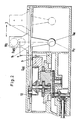
- the rolling stand of the cold pilger rolling mill is designated by WG, which can be displaced in the direction of arrow 1 between the end positions shown in solid lines and in dash-dotted lines.
- the roll stand WG is fastened on the slide 3, which can be moved horizontally in guides 2, the movement of which is generated via the crank mechanism. From the drive, not shown, the rotary movement is transmitted via the drive shaft 4 and the bevel gear pair 5, 6 to the pinion 7, by which the spur gear 8 is driven via the crank 9.
- the crank 9 takes over the mass balance with its entire mass MA.
- the coupling 12 Via a pin 10, with which a pinion 11a is firmly connected and that rolls on an internally toothed gear 11 surrounding the crank 9, the coupling 12 is connected to the crank 9, which receives a rotation opposite to the crank by appropriate superimposition of the rotary movements.
- the coupling 12 is in turn connected to the slide 3 at 13.
- the center of gravity of the roll stand WG is indicated by SWG, which is vertically spaced from the point of application SAG of the centrifugal force of the crank mass MA by the amount a. If the system is designed correctly, the inertial force acting on the center of gravity of the roll stand is equal to the centrifugal force of the crank mass MA acting on the point of application SAG, but because the forces are not on a line of action, a mass moment results. In order to compensate for this mass moment, the additional mass MZ was provided according to the invention, which is attached to an arm 14 on the slide 3.
- This additional mass MZ is spaced from the point of application of the centrifugal force of the masses MA in the vertical plane, as indicated by b, the product of the inertial force for accelerating the mass MZ and the vertical distance b between the points SAG and SM being equalized Mass moment is.
- the roll stand WG is arranged on the slide 3 above the additional mass MZ.
- the coupling 12 engages in the extended part of the slide 3 and thereby takes the roll stand WG and the additional mass MZ with it.
- Figure 3 differs from the illustration in Figure 2 in that the slide 3 is shortened and the connection between the slide 3 and the coupling 12 is made by a connecting rod 15 which is articulated at both ends to the respective components.
Landscapes
- Engineering & Computer Science (AREA)
- Mechanical Engineering (AREA)
- Metal Rolling (AREA)
- Transmission Devices (AREA)
- Transition And Organic Metals Composition Catalysts For Addition Polymerization (AREA)
- Manipulator (AREA)
- Cereal-Derived Products (AREA)
Applications Claiming Priority (3)
| Application Number | Priority Date | Filing Date | Title |
|---|---|---|---|
| DE3706129 | 1987-02-23 | ||
| DE3706129A DE3706129C1 (de) | 1987-02-23 | 1987-02-23 | Antrieb fuer ein Kaltpilgerwalzwerk mit Massen- und Momentenausgleich |
| CA000540656A CA1327134C (fr) | 1986-04-15 | 1987-06-26 | Systeme d'entrainement pour laminoir pas de pelerin a froid |
Publications (2)
| Publication Number | Publication Date |
|---|---|
| EP0280001A1 true EP0280001A1 (fr) | 1988-08-31 |
| EP0280001B1 EP0280001B1 (fr) | 1991-06-26 |
Family
ID=25671398
Family Applications (1)
| Application Number | Title | Priority Date | Filing Date |
|---|---|---|---|
| EP87730137A Expired - Lifetime EP0280001B1 (fr) | 1987-02-23 | 1987-10-29 | Système d'entraînement pour laminoir à froid à pas de pèlerin avec compensation de masse et de moment de rotation |
Country Status (4)
| Country | Link |
|---|---|
| US (1) | US4858458A (fr) |
| EP (1) | EP0280001B1 (fr) |
| JP (1) | JPS63207406A (fr) |
| DE (1) | DE3706129C1 (fr) |
Families Citing this family (4)
| Publication number | Priority date | Publication date | Assignee | Title |
|---|---|---|---|---|
| US5076088A (en) * | 1986-04-15 | 1991-12-31 | Mannesmann Ag | Drive for a pilger cold rolling mill |
| DE4116307C1 (fr) * | 1991-05-15 | 1992-10-29 | Mannesmann Ag, 4000 Duesseldorf, De | |
| DE10241612B3 (de) * | 2002-09-07 | 2004-01-08 | Sms Meer Gmbh | Antriebssystem für ein Kaltpilgerwalzwerk |
| TWI847746B (zh) * | 2023-06-05 | 2024-07-01 | 楊春永 | 交通工具平衡器 |
Citations (4)
| Publication number | Priority date | Publication date | Assignee | Title |
|---|---|---|---|---|
| US2924106A (en) * | 1951-12-29 | 1960-02-09 | Mannesmann Meer Ag | Compensating motion transmitting arrangement for roll housing means |
| US4052898A (en) * | 1976-09-13 | 1977-10-11 | Wean United, Inc. | Crank drive system for cold pilger mills drive or the like |
| SU735342A1 (ru) * | 1977-01-28 | 1980-05-27 | Днепропетровский Ордена Трудового Красного Знамени Металлургический Институт | Привод клети стана холодной прокатки труб |
| DE3613036C1 (en) * | 1986-04-15 | 1987-08-13 | Mannesmann Ag | Drive for cold pilger roll mill |
Family Cites Families (7)
| Publication number | Priority date | Publication date | Assignee | Title |
|---|---|---|---|---|
| DE1427951A1 (de) * | 1963-08-27 | 1969-07-10 | Mannesmann Meer Ag | Antrieb von Walzwerken,insbesondere von Kaltpilgerwalzwerken |
| FR1555869A (fr) * | 1967-12-20 | 1969-01-31 | ||
| DE2312223A1 (de) * | 1973-03-12 | 1974-11-21 | Elektrostalskij Sawod Tjaschel | Rohrkaltwalzwerk |
| DE2329526A1 (de) * | 1973-06-07 | 1975-03-13 | Mannesmann Meer Ag | Kaltpilgerwalzwerk zum rohrwalzen |
| SU592472A1 (ru) * | 1976-10-11 | 1978-02-15 | Предприятие П/Я В-2869 | Привод перемещени клети стана холодной прокатки труб |
| DE3010526A1 (de) * | 1980-03-17 | 1981-09-24 | Mannesmann AG, 4000 Düsseldorf | Pilgerschrittwalzwerk |
| DE3221803C2 (de) * | 1982-06-07 | 1984-06-28 | Mannesmann AG, 4000 Düsseldorf | Antrieb für ein Kaltpilgerwalzwerk |
-
1987
- 1987-02-23 DE DE3706129A patent/DE3706129C1/de not_active Expired
- 1987-10-29 EP EP87730137A patent/EP0280001B1/fr not_active Expired - Lifetime
-
1988
- 1988-02-05 JP JP63025540A patent/JPS63207406A/ja active Pending
- 1988-02-23 US US07/159,191 patent/US4858458A/en not_active Expired - Fee Related
Patent Citations (4)
| Publication number | Priority date | Publication date | Assignee | Title |
|---|---|---|---|---|
| US2924106A (en) * | 1951-12-29 | 1960-02-09 | Mannesmann Meer Ag | Compensating motion transmitting arrangement for roll housing means |
| US4052898A (en) * | 1976-09-13 | 1977-10-11 | Wean United, Inc. | Crank drive system for cold pilger mills drive or the like |
| SU735342A1 (ru) * | 1977-01-28 | 1980-05-27 | Днепропетровский Ордена Трудового Красного Знамени Металлургический Институт | Привод клети стана холодной прокатки труб |
| DE3613036C1 (en) * | 1986-04-15 | 1987-08-13 | Mannesmann Ag | Drive for cold pilger roll mill |
Also Published As
| Publication number | Publication date |
|---|---|
| JPS63207406A (ja) | 1988-08-26 |
| US4858458A (en) | 1989-08-22 |
| EP0280001B1 (fr) | 1991-06-26 |
| DE3706129C1 (de) | 1988-03-10 |
Similar Documents
| Publication | Publication Date | Title |
|---|---|---|
| DE4336422C2 (de) | Kurbeltrieb für ein Kaltpilgerwalzwerk | |
| DD201988A5 (de) | Getriebeanordnung fuer einen mit dem ausleger eines manipulators verbundenen gelenkkopf | |
| DE2740729B2 (de) | Ausgleichssystem für den Antrieb eines Walzgerüstes eines Kaltpilgerwalzwerkes | |
| EP2216107A1 (fr) | Système d'entraînement pour un laminoir, notamment pour un laminoir à pas de pèlerin à froid | |
| EP0280001B1 (fr) | Système d'entraînement pour laminoir à froid à pas de pèlerin avec compensation de masse et de moment de rotation | |
| DE3513705A1 (de) | Industrieroboter mit schwenkarm | |
| DE4124691C1 (fr) | ||
| DE3308413C1 (de) | Spielfrei einstellbarer Schwenkantrieb fuer mindestens eine Hauptachse von Manipulatoren | |
| DE68906055T2 (de) | Gewichtsausgleichsvorrichtung fuer den arm eines roboters oder dergleichen. | |
| DE4442302B4 (de) | Vorrichtung zum axialen hin- und herbewegen von Reibwalzen im Farbwerk von Druckmaschinen | |
| DE3613036C1 (en) | Drive for cold pilger roll mill | |
| DE19511335A1 (de) | Vorrichtung zur Antriebskraftübertragung für einen Schlingenfängerabschnitt in einer Nähmaschine | |
| DE1238788B (de) | Progressive Lenkung fuer Kraftfahrzeuge | |
| DE2850223A1 (de) | Plattenfilterpresse | |
| DE8806352U1 (de) | Kupplung zur Übertragung einer Drehbewegung | |
| DD279829A5 (de) | Antrieb fuer ein kaltpilgerwalzwerk mit massen- und momentenausgleich | |
| EP0649492B1 (fr) | Dispositif de commande entraine par un moteur, pour un battant de porte | |
| EP0642008A2 (fr) | Dispositif d'entraînement de l'axe de mesure d'une machine d'équilibrage | |
| EP0049470A2 (fr) | Transmission à rapport variable, notamment pour tambours à couteaux | |
| DE3221803A1 (de) | Drehmomenten- und massenausgleich fuer ein walzwerk | |
| EP0279334A2 (fr) | Dispositif de levage pour une lingotière de coulée continue | |
| CH655898A5 (de) | Pressenantrieb. | |
| EP0075649B1 (fr) | Transmission à engrenages angulaire | |
| CH674685A5 (fr) | ||
| DE17422C (de) | Neuerungen an Walzwerken |
Legal Events
| Date | Code | Title | Description |
|---|---|---|---|
| PUAI | Public reference made under article 153(3) epc to a published international application that has entered the european phase |
Free format text: ORIGINAL CODE: 0009012 |
|
| AK | Designated contracting states |
Kind code of ref document: A1 Designated state(s): DE FR IT |
|
| 17P | Request for examination filed |
Effective date: 19880910 |
|
| 17Q | First examination report despatched |
Effective date: 19900823 |
|
| GRAA | (expected) grant |
Free format text: ORIGINAL CODE: 0009210 |
|
| ITF | It: translation for a ep patent filed | ||
| AK | Designated contracting states |
Kind code of ref document: B1 Designated state(s): DE FR IT |
|
| ET | Fr: translation filed | ||
| REF | Corresponds to: |
Ref document number: 3771064 Country of ref document: DE Date of ref document: 19910801 |
|
| PLBE | No opposition filed within time limit |
Free format text: ORIGINAL CODE: 0009261 |
|
| STAA | Information on the status of an ep patent application or granted ep patent |
Free format text: STATUS: NO OPPOSITION FILED WITHIN TIME LIMIT |
|
| 26N | No opposition filed | ||
| PGFP | Annual fee paid to national office [announced via postgrant information from national office to epo] |
Ref country code: FR Payment date: 19950925 Year of fee payment: 9 |
|
| PGFP | Annual fee paid to national office [announced via postgrant information from national office to epo] |
Ref country code: DE Payment date: 19951114 Year of fee payment: 9 |
|
| PG25 | Lapsed in a contracting state [announced via postgrant information from national office to epo] |
Ref country code: FR Effective date: 19970630 |
|
| PG25 | Lapsed in a contracting state [announced via postgrant information from national office to epo] |
Ref country code: DE Effective date: 19970701 |
|
| REG | Reference to a national code |
Ref country code: FR Ref legal event code: ST |
|
| PG25 | Lapsed in a contracting state [announced via postgrant information from national office to epo] |
Ref country code: IT Free format text: LAPSE BECAUSE OF NON-PAYMENT OF DUE FEES;WARNING: LAPSES OF ITALIAN PATENTS WITH EFFECTIVE DATE BEFORE 2007 MAY HAVE OCCURRED AT ANY TIME BEFORE 2007. THE CORRECT EFFECTIVE DATE MAY BE DIFFERENT FROM THE ONE RECORDED. Effective date: 20051029 |