EP0280008A1 - Dispositif pour suspendre des conteneurs à déchets ou analogues à un appareil de levage, de préférence à une flèche d'une grue de chargement - Google Patents
Dispositif pour suspendre des conteneurs à déchets ou analogues à un appareil de levage, de préférence à une flèche d'une grue de chargement Download PDFInfo
- Publication number
- EP0280008A1 EP0280008A1 EP88100256A EP88100256A EP0280008A1 EP 0280008 A1 EP0280008 A1 EP 0280008A1 EP 88100256 A EP88100256 A EP 88100256A EP 88100256 A EP88100256 A EP 88100256A EP 0280008 A1 EP0280008 A1 EP 0280008A1
- Authority
- EP
- European Patent Office
- Prior art keywords
- arm
- pulling
- hook
- eye
- load
- Prior art date
- Legal status (The legal status is an assumption and is not a legal conclusion. Google has not performed a legal analysis and makes no representation as to the accuracy of the status listed.)
- Granted
Links
- 239000002699 waste material Substances 0.000 title claims abstract description 14
- 239000000725 suspension Substances 0.000 claims abstract description 3
- 230000006835 compression Effects 0.000 claims description 3
- 238000007906 compression Methods 0.000 claims description 3
- 230000005484 gravity Effects 0.000 claims description 3
- 238000006073 displacement reaction Methods 0.000 claims description 2
- 230000005540 biological transmission Effects 0.000 claims 1
- 239000010720 hydraulic oil Substances 0.000 abstract 1
- 238000004064 recycling Methods 0.000 description 12
- 230000008878 coupling Effects 0.000 description 2
- 238000010168 coupling process Methods 0.000 description 2
- 238000005859 coupling reaction Methods 0.000 description 2
- 238000003780 insertion Methods 0.000 description 2
- 230000037431 insertion Effects 0.000 description 2
- 229910000831 Steel Inorganic materials 0.000 description 1
- 230000007613 environmental effect Effects 0.000 description 1
- 239000011521 glass Substances 0.000 description 1
- 239000002184 metal Substances 0.000 description 1
- 238000000034 method Methods 0.000 description 1
- 239000010893 paper waste Substances 0.000 description 1
- 230000000284 resting effect Effects 0.000 description 1
- 239000010959 steel Substances 0.000 description 1
Images


Classifications
-
- B—PERFORMING OPERATIONS; TRANSPORTING
- B66—HOISTING; LIFTING; HAULING
- B66C—CRANES; LOAD-ENGAGING ELEMENTS OR DEVICES FOR CRANES, CAPSTANS, WINCHES, OR TACKLES
- B66C3/00—Load-engaging elements or devices attached to lifting or lowering gear of cranes or adapted for connection therewith and intended primarily for transmitting lifting forces to loose materials; Grabs
-
- B—PERFORMING OPERATIONS; TRANSPORTING
- B65—CONVEYING; PACKING; STORING; HANDLING THIN OR FILAMENTARY MATERIAL
- B65F—GATHERING OR REMOVAL OF DOMESTIC OR LIKE REFUSE
- B65F1/00—Refuse receptacles; Accessories therefor
- B65F1/12—Refuse receptacles; Accessories therefor with devices facilitating emptying
- B65F1/125—Features allowing the receptacle to be lifted and emptied by its bottom
Definitions
- the invention relates to a device for attaching waste containers or the like, which are provided with a load eye connected to the container trough or bell and a towing eye which is provided on a traction means for opening bottom flaps and / or side parts of the container Hoist, preferably on a boom of a loading crane, with load and pull hooks for each of the eyes.
- batteries from waste containers usually with a closed container bell are provided with bottom flaps which have insertion openings which are adapted to the type of waste to be collected.
- the waste containers are usually provided in the upper area of their bell-shaped housing with round insertion openings for bottles and glass containers, with slot-shaped openings for inserting waste paper and with round or square openings for inserting metal cans.
- bottom flaps or hinged side parts provided with bottom parts, which can open and close like scissors.
- the flaps are provided with pull ropes or rods so that they can be opened by lifting or lowering the pull eyes.
- the containers are also provided with lifting eyes, which are used for lifting, pivoting and / or moving.
- the pulling or lifting eyes are arranged next to each other so that the lifting and pulling hooks of the hoist used for lifting and opening have to be hooked into the eyelets at about the same time.
- a particular problem of the device comprising the load and pull hooks is that the pull hook must be able to be raised and lowered independently in relation to the load hook in order to bring about the opening and closing of the waste container.
- the object of the invention is to provide a device of the type mentioned, which can be handled easily and quickly.
- this object is achieved in a device of the generic type in that a support frame is attached to the output shaft of a rotary motor provided with a suspension device and driven with pressure oil, in which an arm carrying the load hook for the lifting eye is pivotally mounted and which is mounted with an essential vertical guide is provided, in which the support piece of the pulling hook is slidably guided that a hydraulic piston-cylinder unit is arranged in the support frame, the piston rod of which is connected to the pulling eye via a gear or a pulley-like rope and via an actuating piece and one on the arm provided stop or extension gives this a pivoting movement.
- the double hook device enables the load and pull hooks to be coupled to the carrying and pulling eyes of the waste container only by actuating the hydraulic control, since the hooks can close like pliers to couple to the eyes.
- a simple alignment of the hooks on the eyelets is possible in that the support frame carrying the hooks can be rotated into the correct coupling position by the rotary motor.
- the opening of the waste container can be effected in a simple manner by actuating the hydraulic piston-cylinder unit, because the pull hook can be moved relative to the load hook by this.
- the gearbox or pulley-like reeving of the rope designed so that a sufficiently large movement of the pulling hook is achieved with a relatively small piston stroke.
- the arm connected to the load hook is expediently acted upon by a spring, preferably a compression spring, in the direction of its pivoted-in stroke position, in which it rests against a frame-fixed stop, the actuating part connected to the piston rod engaging the arm in the region of the end of the retracting movement of the piston swings out against the force of the spring.
- a spring preferably a compression spring
- a gear for moving the pulling hook relative to the load hook, it expediently has in its final stage a pinion which meshes with a toothed rack connected to the pulling hook.
- the piston rod is connected at its end in a yoke-like manner to an axle on which end pulleys are mounted, that the ends of cables are fastened to the frame, the other ends of which are fastened to the support piece of the pulling hook, and that the cables run from their fixed point on the frame via the cable pulleys movable by the piston rod via deflection rollers mounted in the upper region of the frame to their fixed points on the support piece. Due to this pulley-like reeving, the path of the support piece of the pull hook in its guidance is twice as large as the path of the piston rod, so that a low overall height of the device is possible.
- the lengths of the ropes are expediently dimensioned such that they become slack when the support piece has moved against its lower stop under the action of gravity, so that the arm with the load hook is then pivoted out by further retraction movement of the piston.
- the further retraction and extension movement of the piston can be used solely for pivoting the arm, without any movement being given to the pull hook via the rope.
- the rotary motor is expediently provided with continuous feed and return lines for the pressure medium piston-cylinder unit, so that there is no need to provide rotating hoses which could be damaged by overtightening.
- the load hook is provided with an extension provided with a pin, which is guided telescopically in an overlapping tube, the displacement path being limited by the fact that the pins engage in elongated holes in the tube.
- the pins When lowering, the pins are supported on the lower ends of the elongated holes. If the load hook hits the top wall of the container when the device is lowered, it will not be damaged because the load hook can move upwards in the elongated holes.
- the load hook is latched into the carrying eye after the pivotable lever has been released by the cross member connected to the piston rod by spring force.
- the subsequent release is carried out by taking along an attachment provided on the piston rod.
- the hooks do not perform a vertical hook movement while being latched in and out.
- the piston rod is at its bottom dead center and the of these moving ropes are slack.
- the latches are released and released by a pincer-like movement of the load and pull hooks.
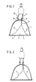
- the recycling container shown schematically in FIGS. 1 to 5 ter 1 is provided with two pivotable bottom flaps 3, 4 about a horizontal axis 2.
- the bottom closure flaps 3, 4 are kept closed under the weight of the bell-shaped housing of the container resting on them.
- the ends of ropes 5, 6 are attached to the outer regions of the bottom flaps 3, 4, the other ends of which are connected to a pull rod 7 which is guided in longitudinally displaceable fashion in guides of the container.
- the pull rod 7 passes through the upper container wall and carries the pulling eye 8 at its upper end.
- the carrying eye 9 is arranged, which is connected to the bell-shaped container trough.
- the load hook 10 can be hooked into the lifting eye 9 and the pull hook 11 into the lifting eye 8.
- the emptied container is then placed back on the floor in reverse order.
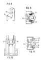
- the device shown in FIGS. 6 to 11 has an upper support frame 20. This consists of a yoke-like cross member 21 which is welded at the end to U-profiles 22, 23 which form the guides for the support piece 24 for the pull hook 25.
- the carrier 21 is welded to two web plates 27, 28 which run obliquely downward and which are connected to one another at their lower end by a welded-in plate 29.
- the web plates 27, 28 are further welded with two tabs 30, 31 which project downwards and which are provided with bearing bores 32, 33 for a shaft or axis on which the arm 34 of the load hook 35 is pivotably mounted.
- bearing plates 37, 38 protruding in pairs in the form of a fork are welded in the area of the ends of the carrier 21, between which the upper deflection rollers 39, 40 are mounted on corresponding axes.
- the cylinder 41 On the sheet 29 connecting the web sheets 27, 28, the cylinder 41 is fastened, the piston rod of which penetrates the sheet 29 downwards.
- the piston rod 46 is welded to a yoke-like cross member 47 on which the cable pulleys 44, 45 are mounted at the end.
- the support arm 34 for the load hook 35 is fastened in the manner shown in FIGS. 6 and 7 on the pivot shaft 60 which is pivotably mounted in the bearing bores 32, 33 of the bearing plates 30, 31.
- the support arm 34 is shown in FIG. 6 with an extension 63 which has a pin 64 which serves to hold a pressure spring, not shown, which is clamped between the extension 63 and the frame-fixed abutment 65.
- yoke-like cross member carrying the movable rope pulleys 44, 45 swings out the arm 34 when the piston rod 46 is retracted via the extension 63, so that it can perform a tong-like movement.
- the swiveled-in stroke position is shown in full lines, while the swiveled-out position is shown in dashed lines. If the transverse yoke 34 moves downwards under tension of the cable 51, the cross member 47 releases the extension 63, so that the arm 34 can perform a pliers-like closing movement relative to the pull hook 25 under the action of the compression spring. If the cross member 47 moves further down, the traction cable 51 is tensioned and accordingly the tensioning hook 25 is raised, in which the support piece 24 moves upwards in the guides 22, 23.
- the cross member 21 of the frame 20 is also provided in its central region with a receiving eye in which the output shaft 70 of the rotary motor 71 is fastened. This is at its upper end between fork-like legs with a bore 72 provided, which serves to attach the rotary motor to the boom of a loading crane.
- the tensioning hook 25 which is welded to the support piece 24, is also shown in its lower and its upper position. If the tensioning hook 25 is in its upper position, the piston rod 46 has extended the rope pulleys 44, 45 into the lowest position in the manner shown.
Landscapes
- Engineering & Computer Science (AREA)
- Mechanical Engineering (AREA)
- Load-Engaging Elements For Cranes (AREA)
- Jib Cranes (AREA)
- Forklifts And Lifting Vehicles (AREA)
Priority Applications (1)
| Application Number | Priority Date | Filing Date | Title |
|---|---|---|---|
| AT88100256T ATE59366T1 (de) | 1987-02-06 | 1988-01-11 | Vorrichtung zum anhaengen von abfallbehaeltern o. dgl. an ein hebezeug, vorzugsweise an einen ausleger eines ladekrans. |
Applications Claiming Priority (2)
| Application Number | Priority Date | Filing Date | Title |
|---|---|---|---|
| DE3703656 | 1987-02-06 | ||
| DE3703656 | 1987-02-06 |
Publications (2)
| Publication Number | Publication Date |
|---|---|
| EP0280008A1 true EP0280008A1 (fr) | 1988-08-31 |
| EP0280008B1 EP0280008B1 (fr) | 1990-12-27 |
Family
ID=6320403
Family Applications (1)
| Application Number | Title | Priority Date | Filing Date |
|---|---|---|---|
| EP88100256A Expired - Lifetime EP0280008B1 (fr) | 1987-02-06 | 1988-01-11 | Dispositif pour suspendre des conteneurs à déchets ou analogues à un appareil de levage, de préférence à une flèche d'une grue de chargement |
Country Status (4)
| Country | Link |
|---|---|
| EP (1) | EP0280008B1 (fr) |
| JP (1) | JP2773868B2 (fr) |
| AT (1) | ATE59366T1 (fr) |
| DE (1) | DE3861388D1 (fr) |
Cited By (15)
| Publication number | Priority date | Publication date | Assignee | Title |
|---|---|---|---|---|
| EP0399280A3 (en) * | 1989-05-12 | 1990-12-19 | Kinshofer Greiftechnik Gmbh | Container with manipulation device |
| FR2704538A1 (fr) * | 1993-04-26 | 1994-11-04 | Polz Sarl | Dispositif de préhension de conteneurs. |
| DE4441551C1 (de) * | 1994-11-02 | 1996-02-01 | Kinshofer Greiftechnik | Vorrichtung zum hängenden Anheben und Entleeren von Behältern, Containern od. dgl. |
| WO1996026138A1 (fr) * | 1995-02-21 | 1996-08-29 | Froederberg Per Arne | Conteneur a fond mobile |
| AT402914B (de) * | 1989-08-01 | 1997-09-25 | Transporte Waizinger Ges M B H | Vorrichtung zum verladen und entleeren von altstoffsammelbehältern |
| ES2127679A1 (es) * | 1996-04-18 | 1999-04-16 | Ramis Rubio Antonio | Sistema de enganche, sujeccion, apertura y cierre para contenedores de residuos solidos. |
| ES2147102A1 (es) * | 1997-10-29 | 2000-08-16 | Allibert Equipement | Contenedor de recogida selectiva. |
| RU2408516C1 (ru) * | 2009-10-08 | 2011-01-10 | Открытое акционерное общество Акционерная холдинговая компания "Всероссийский научно-исследовательский и проектно-конструкторский институт металлургического машиностроения имени академика Целикова" (ОАО АХК "ВНИИМЕТМАШ") | Комплекс для подземного сбора и хранения твердых бытовых отходов |
| CN103241650A (zh) * | 2013-05-22 | 2013-08-14 | 江苏句容联合铜材有限公司 | 一种变压器用电磁线生产厂房内的行车防尘方法 |
| EP2585388A4 (fr) * | 2010-06-23 | 2015-07-01 | Bulk Box Logistics Pty Ltd | Contenant à déchargement par le bas |
| CN107318752A (zh) * | 2017-08-11 | 2017-11-07 | 池州市忠友生态农业开发有限公司 | 一种水产养殖废水循环处理系统 |
| CN112777482A (zh) * | 2021-02-19 | 2021-05-11 | 国网山东省电力公司枣庄供电公司 | 一种多功能、多用途起重置物架 |
| CN114308356A (zh) * | 2021-11-30 | 2022-04-12 | 湖南恒瑞管桩科技有限公司 | 智能化人工制沙提升系统 |
| CN114852531A (zh) * | 2022-06-01 | 2022-08-05 | 宁波长荣酿造设备有限公司 | 料斗 |
| CN115489893A (zh) * | 2022-09-16 | 2022-12-20 | 南华大学 | 放射性粉末物料储料罐及其拆盖装盖方法 |
Families Citing this family (2)
| Publication number | Priority date | Publication date | Assignee | Title |
|---|---|---|---|---|
| JPH07172759A (ja) * | 1993-12-20 | 1995-07-11 | Nishio Rentooole Kk | クランプ装置 |
| CN105060114A (zh) * | 2015-09-10 | 2015-11-18 | 无锡市运达机械有限公司 | 起重机制动器刹车防落灰除尘装置 |
Citations (7)
| Publication number | Priority date | Publication date | Assignee | Title |
|---|---|---|---|---|
| FR378633A (fr) * | 1907-06-08 | 1907-10-10 | Clark Chase | Système de benne pour transporteur à cable |
| GB277259A (en) * | 1927-05-18 | 1927-09-15 | John Borthwick Nixon | Improvements relating to skips |
| DE1275736B (de) * | 1965-10-08 | 1968-08-22 | Krupp Gmbh | Selbstgreifende Kreuztraverse |
| DE2521021A1 (de) * | 1975-05-12 | 1976-11-25 | Kijewski Hans Joachim Ing Grad | Hydraulisch betaetigte haengetraverse |
| DE2804954A1 (de) * | 1978-02-06 | 1979-08-09 | Ludmann Gmbh & Co Kg Karl | Container |
| FR2539112A1 (fr) * | 1983-01-07 | 1984-07-13 | Guerid Jean | Dispositif de vidage par fond ouvrant de conteneurs et receptables pour produits en vrac |
| AU559326B2 (en) * | 1982-12-09 | 1987-03-05 | Industrial Containers Pty. Ltd. | Waste container |
-
1988
- 1988-01-11 AT AT88100256T patent/ATE59366T1/de not_active IP Right Cessation
- 1988-01-11 EP EP88100256A patent/EP0280008B1/fr not_active Expired - Lifetime
- 1988-01-11 DE DE8888100256T patent/DE3861388D1/de not_active Expired - Lifetime
- 1988-02-04 JP JP63022952A patent/JP2773868B2/ja not_active Expired - Fee Related
Patent Citations (7)
| Publication number | Priority date | Publication date | Assignee | Title |
|---|---|---|---|---|
| FR378633A (fr) * | 1907-06-08 | 1907-10-10 | Clark Chase | Système de benne pour transporteur à cable |
| GB277259A (en) * | 1927-05-18 | 1927-09-15 | John Borthwick Nixon | Improvements relating to skips |
| DE1275736B (de) * | 1965-10-08 | 1968-08-22 | Krupp Gmbh | Selbstgreifende Kreuztraverse |
| DE2521021A1 (de) * | 1975-05-12 | 1976-11-25 | Kijewski Hans Joachim Ing Grad | Hydraulisch betaetigte haengetraverse |
| DE2804954A1 (de) * | 1978-02-06 | 1979-08-09 | Ludmann Gmbh & Co Kg Karl | Container |
| AU559326B2 (en) * | 1982-12-09 | 1987-03-05 | Industrial Containers Pty. Ltd. | Waste container |
| FR2539112A1 (fr) * | 1983-01-07 | 1984-07-13 | Guerid Jean | Dispositif de vidage par fond ouvrant de conteneurs et receptables pour produits en vrac |
Cited By (17)
| Publication number | Priority date | Publication date | Assignee | Title |
|---|---|---|---|---|
| EP0399280A3 (en) * | 1989-05-12 | 1990-12-19 | Kinshofer Greiftechnik Gmbh | Container with manipulation device |
| AT402914B (de) * | 1989-08-01 | 1997-09-25 | Transporte Waizinger Ges M B H | Vorrichtung zum verladen und entleeren von altstoffsammelbehältern |
| FR2704538A1 (fr) * | 1993-04-26 | 1994-11-04 | Polz Sarl | Dispositif de préhension de conteneurs. |
| DE4441551C1 (de) * | 1994-11-02 | 1996-02-01 | Kinshofer Greiftechnik | Vorrichtung zum hängenden Anheben und Entleeren von Behältern, Containern od. dgl. |
| WO1996026138A1 (fr) * | 1995-02-21 | 1996-08-29 | Froederberg Per Arne | Conteneur a fond mobile |
| ES2127679A1 (es) * | 1996-04-18 | 1999-04-16 | Ramis Rubio Antonio | Sistema de enganche, sujeccion, apertura y cierre para contenedores de residuos solidos. |
| ES2147102A1 (es) * | 1997-10-29 | 2000-08-16 | Allibert Equipement | Contenedor de recogida selectiva. |
| RU2408516C1 (ru) * | 2009-10-08 | 2011-01-10 | Открытое акционерное общество Акционерная холдинговая компания "Всероссийский научно-исследовательский и проектно-конструкторский институт металлургического машиностроения имени академика Целикова" (ОАО АХК "ВНИИМЕТМАШ") | Комплекс для подземного сбора и хранения твердых бытовых отходов |
| EP2585388A4 (fr) * | 2010-06-23 | 2015-07-01 | Bulk Box Logistics Pty Ltd | Contenant à déchargement par le bas |
| CN103241650A (zh) * | 2013-05-22 | 2013-08-14 | 江苏句容联合铜材有限公司 | 一种变压器用电磁线生产厂房内的行车防尘方法 |
| CN107318752A (zh) * | 2017-08-11 | 2017-11-07 | 池州市忠友生态农业开发有限公司 | 一种水产养殖废水循环处理系统 |
| CN112777482A (zh) * | 2021-02-19 | 2021-05-11 | 国网山东省电力公司枣庄供电公司 | 一种多功能、多用途起重置物架 |
| CN114308356A (zh) * | 2021-11-30 | 2022-04-12 | 湖南恒瑞管桩科技有限公司 | 智能化人工制沙提升系统 |
| CN114308356B (zh) * | 2021-11-30 | 2022-12-20 | 湖南恒瑞管桩科技有限公司 | 智能化人工制沙提升系统 |
| CN114852531A (zh) * | 2022-06-01 | 2022-08-05 | 宁波长荣酿造设备有限公司 | 料斗 |
| CN115489893A (zh) * | 2022-09-16 | 2022-12-20 | 南华大学 | 放射性粉末物料储料罐及其拆盖装盖方法 |
| CN115489893B (zh) * | 2022-09-16 | 2023-06-16 | 南华大学 | 放射性粉末物料储料罐及其拆盖装盖方法 |
Also Published As
| Publication number | Publication date |
|---|---|
| JPS63262389A (ja) | 1988-10-28 |
| JP2773868B2 (ja) | 1998-07-09 |
| DE3861388D1 (de) | 1991-02-07 |
| ATE59366T1 (de) | 1991-01-15 |
| EP0280008B1 (fr) | 1990-12-27 |
Similar Documents
| Publication | Publication Date | Title |
|---|---|---|
| EP0280008B1 (fr) | Dispositif pour suspendre des conteneurs à déchets ou analogues à un appareil de levage, de préférence à une flèche d'une grue de chargement | |
| DE3123161A1 (de) | Fahrzeug mit seitlicher einrichtung zur handhabung von behaeltern im allgemeinen | |
| DE4441551C1 (de) | Vorrichtung zum hängenden Anheben und Entleeren von Behältern, Containern od. dgl. | |
| EP1506127B1 (fr) | Dispositif de levage pour conteneurs | |
| DE2747069A1 (de) | Hebevorrichtung mit wahlweisem einsatz eines flaschenzuges oder zweier flaschenzuege | |
| DE3413937A1 (de) | Anordnung zum betaetigen eines klappbehaelters | |
| EP0143197B1 (fr) | Disposition pour actionner une benne preneuse | |
| DE958594C (de) | Selbstschliessende, verstellbare Blockzange | |
| WO2021228329A1 (fr) | Dispositif de préhension doté d'un système de commande de fermeture par multiplication de force démultipliée | |
| DE4019618A1 (de) | Fahrzeug zum im senkrechtstehenden zustand aufnehmen und absetzen von behaeltern | |
| EP0338492B1 (fr) | Benne pour la collecte séparée de matériaux différents | |
| DE3650245T2 (de) | Dachhebemechanismus eines Anhängers oder einer Lastkraftwagen-Kastenkonstruktion. | |
| EP0594017A1 (fr) | Conteneur formé de plusieurs coquilles articulées et ayant plusieurs compartiments | |
| DE1293433B (de) | Transport- und Greifeinrichtung fuer grosse Lasten | |
| DE4137399A1 (de) | Greifvorrichtung fuer rohre | |
| DE4017544A1 (de) | Behaelter mit bodenklappe | |
| DE3336935C2 (de) | Seilschrappervorrichtung | |
| EP0467419B1 (fr) | Dispositif pour accrocher et ouvrir des bennes-coquilles | |
| DE2524622A1 (de) | Geraet zum entleeren oben offener behaelter, insbesondere von sinkschachteimern | |
| DE7702842U1 (de) | Bagger | |
| DE493772C (de) | Kranverladevorrichtung fuer Pressstuecke, wie Brikette u. dgl. | |
| DE3512431C1 (de) | Heukran | |
| DE1956920A1 (de) | Lastfahrzeug mit einer Ladebruecke und einem ueber der Ladebruecke angeordneten Ladekran | |
| DE956477C (de) | Kippvorrichtung fuer Behaelter | |
| EP4053066A2 (fr) | Dispositif et procédé de montage / démontage d'une flèche de grue mobile |
Legal Events
| Date | Code | Title | Description |
|---|---|---|---|
| PUAI | Public reference made under article 153(3) epc to a published international application that has entered the european phase |
Free format text: ORIGINAL CODE: 0009012 |
|
| AK | Designated contracting states |
Kind code of ref document: A1 Designated state(s): AT BE CH DE FR GB IT LI LU NL SE |
|
| 17P | Request for examination filed |
Effective date: 19880927 |
|
| 17Q | First examination report despatched |
Effective date: 19890616 |
|
| GRAA | (expected) grant |
Free format text: ORIGINAL CODE: 0009210 |
|
| AK | Designated contracting states |
Kind code of ref document: B1 Designated state(s): AT BE CH DE FR GB IT LI LU NL SE |
|
| REF | Corresponds to: |
Ref document number: 59366 Country of ref document: AT Date of ref document: 19910115 Kind code of ref document: T |
|
| GBT | Gb: translation of ep patent filed (gb section 77(6)(a)/1977) | ||
| REF | Corresponds to: |
Ref document number: 3861388 Country of ref document: DE Date of ref document: 19910207 |
|
| ET | Fr: translation filed | ||
| ITF | It: translation for a ep patent filed | ||
| PLBE | No opposition filed within time limit |
Free format text: ORIGINAL CODE: 0009261 |
|
| STAA | Information on the status of an ep patent application or granted ep patent |
Free format text: STATUS: NO OPPOSITION FILED WITHIN TIME LIMIT |
|
| 26N | No opposition filed | ||
| ITTA | It: last paid annual fee | ||
| EPTA | Lu: last paid annual fee | ||
| EAL | Se: european patent in force in sweden |
Ref document number: 88100256.2 |
|
| REG | Reference to a national code |
Ref country code: GB Ref legal event code: IF02 |
|
| PGFP | Annual fee paid to national office [announced via postgrant information from national office to epo] |
Ref country code: GB Payment date: 20031222 Year of fee payment: 17 |
|
| PGFP | Annual fee paid to national office [announced via postgrant information from national office to epo] |
Ref country code: FR Payment date: 20040123 Year of fee payment: 17 |
|
| PGFP | Annual fee paid to national office [announced via postgrant information from national office to epo] |
Ref country code: NL Payment date: 20040126 Year of fee payment: 17 Ref country code: AT Payment date: 20040126 Year of fee payment: 17 |
|
| PGFP | Annual fee paid to national office [announced via postgrant information from national office to epo] |
Ref country code: LU Payment date: 20040127 Year of fee payment: 17 Ref country code: DE Payment date: 20040127 Year of fee payment: 17 Ref country code: BE Payment date: 20040127 Year of fee payment: 17 |
|
| PGFP | Annual fee paid to national office [announced via postgrant information from national office to epo] |
Ref country code: SE Payment date: 20040128 Year of fee payment: 17 |
|
| PGFP | Annual fee paid to national office [announced via postgrant information from national office to epo] |
Ref country code: CH Payment date: 20040129 Year of fee payment: 17 |
|
| PG25 | Lapsed in a contracting state [announced via postgrant information from national office to epo] |
Ref country code: LU Free format text: LAPSE BECAUSE OF NON-PAYMENT OF DUE FEES Effective date: 20050111 Ref country code: IT Free format text: LAPSE BECAUSE OF NON-PAYMENT OF DUE FEES;WARNING: LAPSES OF ITALIAN PATENTS WITH EFFECTIVE DATE BEFORE 2007 MAY HAVE OCCURRED AT ANY TIME BEFORE 2007. THE CORRECT EFFECTIVE DATE MAY BE DIFFERENT FROM THE ONE RECORDED. Effective date: 20050111 Ref country code: GB Free format text: LAPSE BECAUSE OF NON-PAYMENT OF DUE FEES Effective date: 20050111 Ref country code: AT Free format text: LAPSE BECAUSE OF NON-PAYMENT OF DUE FEES Effective date: 20050111 |
|
| PG25 | Lapsed in a contracting state [announced via postgrant information from national office to epo] |
Ref country code: SE Free format text: LAPSE BECAUSE OF NON-PAYMENT OF DUE FEES Effective date: 20050112 |
|
| PG25 | Lapsed in a contracting state [announced via postgrant information from national office to epo] |
Ref country code: LI Free format text: LAPSE BECAUSE OF NON-PAYMENT OF DUE FEES Effective date: 20050131 Ref country code: CH Free format text: LAPSE BECAUSE OF NON-PAYMENT OF DUE FEES Effective date: 20050131 Ref country code: BE Free format text: LAPSE BECAUSE OF NON-PAYMENT OF DUE FEES Effective date: 20050131 |
|
| BERE | Be: lapsed |
Owner name: *KINSHOFER GREIFTECHNIK G.M.B.H. Effective date: 20050131 |
|
| PG25 | Lapsed in a contracting state [announced via postgrant information from national office to epo] |
Ref country code: NL Free format text: LAPSE BECAUSE OF NON-PAYMENT OF DUE FEES Effective date: 20050801 |
|
| PG25 | Lapsed in a contracting state [announced via postgrant information from national office to epo] |
Ref country code: DE Free format text: LAPSE BECAUSE OF NON-PAYMENT OF DUE FEES Effective date: 20050802 |
|
| EUG | Se: european patent has lapsed | ||
| GBPC | Gb: european patent ceased through non-payment of renewal fee |
Effective date: 20050111 |
|
| REG | Reference to a national code |
Ref country code: CH Ref legal event code: PL |
|
| PG25 | Lapsed in a contracting state [announced via postgrant information from national office to epo] |
Ref country code: FR Free format text: LAPSE BECAUSE OF NON-PAYMENT OF DUE FEES Effective date: 20050930 |
|
| NLV4 | Nl: lapsed or anulled due to non-payment of the annual fee |
Effective date: 20050801 |
|
| REG | Reference to a national code |
Ref country code: FR Ref legal event code: ST |
|
| BERE | Be: lapsed |
Owner name: *KINSHOFER GREIFTECHNIK G.M.B.H. Effective date: 20050131 |