EP0280024A1 - Drehverschluss für Behälter - Google Patents
Drehverschluss für Behälter Download PDFInfo
- Publication number
- EP0280024A1 EP0280024A1 EP88100596A EP88100596A EP0280024A1 EP 0280024 A1 EP0280024 A1 EP 0280024A1 EP 88100596 A EP88100596 A EP 88100596A EP 88100596 A EP88100596 A EP 88100596A EP 0280024 A1 EP0280024 A1 EP 0280024A1
- Authority
- EP
- European Patent Office
- Prior art keywords
- ring
- screw ring
- screw
- twist lock
- cover
- Prior art date
- Legal status (The legal status is an assumption and is not a legal conclusion. Google has not performed a legal analysis and makes no representation as to the accuracy of the status listed.)
- Granted
Links
- 229910052751 metal Inorganic materials 0.000 claims abstract description 20
- 239000002184 metal Substances 0.000 claims abstract description 20
- 238000007789 sealing Methods 0.000 claims abstract description 20
- 239000004033 plastic Substances 0.000 claims abstract description 12
- 239000011324 bead Substances 0.000 claims description 6
- 230000004308 accommodation Effects 0.000 abstract 1
- 238000010276 construction Methods 0.000 abstract 1
- 239000011521 glass Substances 0.000 description 7
- 238000004519 manufacturing process Methods 0.000 description 2
- 239000000463 material Substances 0.000 description 2
- 238000004806 packaging method and process Methods 0.000 description 2
- WZZBNLYBHUDSHF-DHLKQENFSA-N 1-[(3s,4s)-4-[8-(2-chloro-4-pyrimidin-2-yloxyphenyl)-7-fluoro-2-methylimidazo[4,5-c]quinolin-1-yl]-3-fluoropiperidin-1-yl]-2-hydroxyethanone Chemical compound CC1=NC2=CN=C3C=C(F)C(C=4C(=CC(OC=5N=CC=CN=5)=CC=4)Cl)=CC3=C2N1[C@H]1CCN(C(=O)CO)C[C@@H]1F WZZBNLYBHUDSHF-DHLKQENFSA-N 0.000 description 1
- 239000004743 Polypropylene Substances 0.000 description 1
- 238000005299 abrasion Methods 0.000 description 1
- 229910052782 aluminium Inorganic materials 0.000 description 1
- XAGFODPZIPBFFR-UHFFFAOYSA-N aluminium Chemical compound [Al] XAGFODPZIPBFFR-UHFFFAOYSA-N 0.000 description 1
- 230000005540 biological transmission Effects 0.000 description 1
- 150000001875 compounds Chemical class 0.000 description 1
- 238000005516 engineering process Methods 0.000 description 1
- 238000003780 insertion Methods 0.000 description 1
- 230000037431 insertion Effects 0.000 description 1
- -1 polypropylene Polymers 0.000 description 1
- 229920001155 polypropylene Polymers 0.000 description 1
Images


Classifications
-
- B—PERFORMING OPERATIONS; TRANSPORTING
- B65—CONVEYING; PACKING; STORING; HANDLING THIN OR FILAMENTARY MATERIAL
- B65D—CONTAINERS FOR STORAGE OR TRANSPORT OF ARTICLES OR MATERIALS, e.g. BAGS, BARRELS, BOTTLES, BOXES, CANS, CARTONS, CRATES, DRUMS, JARS, TANKS, HOPPERS, FORWARDING CONTAINERS; ACCESSORIES, CLOSURES, OR FITTINGS THEREFOR; PACKAGING ELEMENTS; PACKAGES
- B65D51/00—Closures not otherwise provided for
- B65D51/14—Rigid discs or spherical members adapted to be held in sealing engagement with mouth of container, e.g. closure plates for preserving jars
- B65D51/145—Rigid discs or spherical members adapted to be held in sealing engagement with mouth of container, e.g. closure plates for preserving jars by means of an additional element connected directly to the container
Definitions
- the invention relates to a rotary closure for containers with a mouth, on the end face of which an annular surface cooperating with a sealing ring of the closure and on the periphery of which the rotary connection is provided are provided threads which cooperate with corresponding threads on an apron section of the rotary closure, the rotary closure being formed in two parts and consists of a screw ring with a thread and a plate-shaped cover part with the sealing ring, which is arranged in a form-fitting manner with the screw ring at an axial distance above the area of the thread and the screw ring consists of a moldable plastic and the cover part consists of sheet metal.
- a rotary closure for containers has already been proposed, as specified in the preamble of claim 1 (DE-OS 33 22 326).
- the sheet metal cover must be inserted from the open thread side of the screw ring, and therefore the outer diameter of the sheet metal cover may only be made slightly larger than the inner edge of the support ring or thread tips in the screw ring to prevent abrasion to avoid that can get into the filling material and due to the overlapping flange part can spring open only a little.
- the sheet thickness of the cover is available as support for the sheet metal cover when screwing on in the screw ring, which must be regarded as unfavorable because of the manufacturing tolerances.
- the shrink tolerance in the plastic screw ring in particular exceeds the small contact area.
- the present invention is therefore based on the object of developing a rotary closure of the type mentioned in such a way that a good seal can be achieved after filling and also after opening when the container is reclosed.
- a twist lock of the type mentioned is proposed, which is characterized by the features specified in claim 1.
- a two-part twist lock has been created, in which there is a non-positive connection between the cover part made of sheet metal and the screw ring made of plastic, the connection between the screw ring and the cover part being such that they can be rotated relative to one another and can be opened without play. and unscrewing the screw cap on an appropriate container is made possible. It ensures that the seal in the lid is pressed onto the end face of the container neck by pulling sideways as with any one-piece screw cap.
- twist lock better enables an important requirement, namely the sealing of the glass container, that the lid is pulled laterally onto the mouth by the screw ring.
- an important requirement namely the sealing of the glass container, that the lid is pulled laterally onto the mouth by the screw ring.
- an outwardly circumferential annular bead is formed, which engages in a correspondingly designed circumferential counterpart arranged on the screw ring, and that Has section above and below the bead centering sections.
- the ring part is designed in such a way that a strong turning is made possible and that an engagement part is arranged at the lower end of the ring part, which is designed as a curl. Since tensile forces are to be transmitted from the screw ring to the cover, it is advantageous to design the engaging part as a closed curl or to reduce the rigidity as an interrupted curl.
- the engagement form in the screw ring is designed by an angular bead so that the curling is always fixed.
- the screw ring with a centering for the sheet metal lid and for the container is also provided. Here, too, the insertion takes place from the top of the screw ring.
- the ring part consists of a vertical section and an engagement part is arranged at the lower end of the ring part, which as an outwardly offset open step, which consists of a flange for power transmission and an adjoining vertical part , is formed and is arranged in an inwardly open, approximately rectangular cross-section having an annular groove of the screw ring.
- This shape should be used when the thread from the container begins deeper at the mouth, so that the glass wall can be drawn in, i.e. kept thinner, and the sheet metal cover also becomes smaller (ring channel at the mouth).
- the protrusion of the step from the thread of the screw ring is less, so that the metal cover can be inserted from the threaded side of the screw ring.
- the part of the screw ring located above the step is designed as a centering for the sheet metal cover.
- a rotary lock of the type mentioned is registered, in which a lower closed groove shape is provided as an engaging part for receiving the screw ring after the vertical ring part.
- This closed step shape is another excellent embodiment of the invention.
- the screw ring consists only of the threaded part, which is preferably provided with a nut thread, the cover being pushed into the initially still open gripping section and subsequently through the flanging is positively connected.
- This embodiment enables full printing of the side cover part of the sheet metal cover, and as a result the monochrome screw ring made of plastic is completely covered.
- a rotary closure 100 which consists of a screw ring 10 and a cover part 20 and with which the mouth of a container neck of a container 50, not shown in the drawing, is closed.
- the screw ring 10 which is made of a moldable plastic, e.g. made of polypropylene, has in its lower region inwardly directed thread segments 40 which can be engaged in corresponding thread segments 51 on the outside of the container neck in order to enable a screw connection.
- the cover 20 is made of sheet metal, preferably of deformable aluminum sheet, and has an approximately plate-like shape, which consists of a closure part 25 with an adjoining downwardly open sealing channel 26 in which the sealing ring or sealing compound 30 is arranged the upper end face 50a of the container neck of the container 50 can be placed in a sealing manner.
- a ring part bent downwards which consists of a section 21a and b, in which a bead 22 is formed which extends outwards and engages in a counterpart 60 designed as an annular groove 11.
- the cover 120 has a downwardly deformed ring part 121 adjoining the sealing channel 126, at the lower end of which an engagement part 122 is arranged, which consists of a circular cross-section of flanging or curling and into a engages in the screw ring 110 formed annular groove 111.
- the screw ring 110 is provided with a vertical centering section 116 which is adjoined by an angular bead which is designed as an annular groove with conical inlet flanks.
- the lid part 120 is pulled onto the container neck via the annular groove 111 and the engaging part 122, so that a secure seal is ensured via the sealing compound 130 even if the container neck is not planar. Since the annular groove 111 and the engaging part 122 have corresponding shapes, a play-free, positive connection 160 of the cover part 120 in the screw ring 110 is ensured.
- the centering ring 112 which can also consist of ring elements, is arranged below the ring groove 111.
- the centering ring 112 is dimensioned in its inner or contact surface diameter D2 in such a way that it centers the screw ring 110 and thus the rotary closure 200 on the container neck. This makes it possible, despite the tolerances to be provided for manufacturing reasons, between the screw ring-side and container neck-side thread segments to apply a high screwing or tightening torque without the risk of the thread segments being pushed apart.
- the sheet metal cover is thus inserted into the screw ring. That the curling can be interrupted and thus can dodge elastically and then snaps into the engaging form.
- the curling can move as far as the container wall by turning it too hard or unscrewing it, but it remains non-positively connected.
- the cover part 220 has the same basic elements as described above.
- the sealing channel 226 is followed by a downwardly bent ring part 221, on which an outwardly displaced step, consisting of a flange 222a, is arranged as the engaging part, and a vertical part 222b is arranged thereon, which engages in an annular groove 211 formed in the screw ring, which forms the form-fitting counterpart 260 of the screw ring 210.
- the screw ring has a centering section 216 opposite the ring part 121, to which the annular groove 211 and then a holding section 217 adjoins, a thread 218 being cut in the holding section 217 into the corresponding thread segment 51 on the outside of the container neck of the container 50 can be engaged to enable a screw connection.
- the cover part 320; 320 ⁇ has the same basic elements as those described above.
- the screw ring 310 is designed as a simple ring insert, in the holding section 311 of which a thread 312 is cut, into which corresponding thread segments 51 on the outside of the container neck of the container 50 can be engaged in order to enable a screw connection.
Landscapes
- Engineering & Computer Science (AREA)
- Mechanical Engineering (AREA)
- Closures For Containers (AREA)
- Extrusion Moulding Of Plastics Or The Like (AREA)
- Mechanical Operated Clutches (AREA)
Abstract
Description
- Die Erfindung betrifft einen Drehverschluß für Behälter mit einer Mündung, an dessen Stirnfläche eine mit einem Dichtungsring des Verschlusses abdichtend zusammenwirkende Ringfläche und an dessen Umfang die Drehverbindung ermöglichende Gewinde vorgesehen sind, die mit entsprechenden Gewinde an einem Schürzenabschnitt des Drehverschlusses zusammenwirken, wobei der Drehverschluß zweiteilig ausgebildet ist und aus einem die Gewinde aufweisendem Schraubring und einem tellerförmigen den Dichtungsring aufweisenden Deckelteil besteht, der zum Schraubring formschlüssig in einem axialen Abstand oberhalb des Bereiches der Gewinde angeordnet ist und der Schraubring aus einem formbaren Kunststoff und der Deckelteil aus Blech besteht.
- Auf dem Gebiet der Verschlüsse für Verpackungsbehälter ist die Entwicklung dahingehend zu beobachten, daß versucht wird, einen kombinierten Verschluß aus einem Blechteil und einem Kunststoffteil zu konzipieren. Dabei wird der Blechdeckel - mit einem PVC-Dichtungsring versehen - als Abdichtung für den Behälter benutzt und der Schraubring aus Kunststoff als Befestigungsteil auf dem Behälterhals verwendet. Besonders für die Leichtglasentwicklung hat dies Vorteile, weil dadurch die Befestigungselemente, wie die Gewindesegmente, glastechnisch optimal gestaltet werden können.
- So ist bereits ein Drehverschluß für Behälter vorgeschlagen worden, wie er im Oberbegriff des Anspruchs 1 angegeben ist (DE-OS 33 22 326). Bei einem derartigen Deckel is eine Formschlüssigkeit zwischen Blachdeckel und dem Kunststoffring nicht zu erreichen, da der Blechdeckel von der offenen Gewindeseite des Schraubringes eingebracht werden muß, und daher der Außendurchmesser des Blechdeckels nur wenig größer als die Innenkante des Auflageringes oder Gewindespitzen im Schraubring ausgeführt werden darf, um Abrieb zu vermeiden, das ins Füllgut gelangen kann und wegen des übergreifenden Flanschteiles nur wenig auffedern kann. Als Auflage des Blechdeckels beim Aufschrauben im Schraubring steht dann nur die Blechstärke des Deckels zur Verfügung, was wegen der Herstellungs-toleranzen als ungünstig angesehen werden muß. Besonders die Schrumpftoleranz beim Kunststoffschraubring übersteigt den kleinen Auflagebereich.
- Insbesondere wenn ein derartiger Drehverschluß für Behälter verwendet wird, bei denen nach dem Befüllen ein Vakuum erzeugt wird, zeigen sich auch noch weitere Nachteile einer losen Verbindung, da der Blechdeckel durch das Vakuum auf der Behältermündung gehalten wird, so daß der Schraubring nicht mehr dem Deckel verbunden ist. Der Schraubring wird dann nur durch Reibung am Gewinde gehalten und kann sich lockern, so daß bei Käufern derartiger Verpackungsbehälter der Eindruck entstehen kann, daß der Behälter bereits geöffnet ist.
- Der vorliegenden Erfindung liegt daher die Aufgabe zugrunde, einen Drehverschluß der eingangs benannten Art so weiterzubilden, daß eine gute Abdichtung nach der Abfüllung und auch nach dem Öffnen beim Wiederverschließen des Behälters erreichbar ist.
- Zur Lösung dieser Aufgabe wird daher ein Drehverschluß der eingangs genannten Art vorgeschlagen, der durch die im Anspruch 1 angegebenen Merkmale gekennzeichnet ist. Es ist auf diese Weise ein zweiteiliger Drehverschluß geschaffen worden, bei dem eine kraftschlüssige Verbindung zwischen dem Deckelteil aus Blech und dem Schraubring aus Kunststoff besteht, wobei die Verbindung zwischen dem Schraubring und dem Deckelteil so ist, daß diese gegeneinander verdrehbar sind und ein spielfreies Auf- und Abschrauben des Drehverschlusses auf einen entsprechenden Behälter ermöglicht ist. Es sichergestellt, durch seitliches Ziehen wie bei jedem einteiligen Schraubverschluß die Dichtung im Deckel auf die Stirnfläche des Behälterhalses aufzudrücken.
- Eine derartige Ausbildung des Drehverschlusses ermöglicht besser eine wichtige Voraussetzung, nämlich die Abdichtung der Glasbehälter, daß der Deckel durch den Schraubring seitlich auf die Mündung gezogen wird. Durch ein konzentrisches Aufdrücken durch ein Übergreifen des Schraubringes auf den Deckel im Bereich des Dichtungsringes ist eine gleichmäßige Abdichtung auch bei geringen Unplanheiten nicht zu erreichen.
- Gemäß einer bevorzugten Ausführungsform der Erfindung ist vorgesehen, daß als Gegenform an dem Ringteil, das aus einem senkrechten Abschnitt besteht, eine nach aussen umlaufende ringförmigen Sicke ausgebildet ist, die in ein entsprechend ausgebildetes, an dem Schraubring angeordnetes umlaufende Gegenstück eingreifend ist, und daß der Abschnitt oberhalb und unterhalb der Sicke Zentrierungsabschnitte aufweist.
- Bei dieser Konzeption des Drehverschlusses ergibt sich die Möglichkeit, zwischen Blechdeckel und Gewinde eine Zentrierung für den Schraubring vorzusehen, obwohl der Blechdeckel nur geringe Ovalitäten der Glasbehälter ausgleichen muß und dadurch selbstzentrierend, so daß der Decken von der Oberseite in den Schraubring, also vom Gewinde abgewandten Seite eingebracht werden muß, aber hierdurch kann das aufbringbare Zudrehmoment verstärkt werden, ohne daß ein Verschieben auf dem Glas durch Wegdrücken der Zusammenarbeitenden Gewindesegmente auftreten kann.
- Gemäß einer weiteren bevorzugten Ausführungsform der Erfindung ist vorgesehen, daß das Ringteil so ausgebildet ist, daß ein kräftiges Zudrehen ermöglicht wird und daß am unteren Ende des Ringteiles ein Eingreifteil angeordnet ist, das als Rollierung ausgebildet ist.
Da vom Schraubring auf den Deckel Zugkräfte zu übertragen sind, ist es vorteilhaft, das Eingreifteil als geschlossene Rollierung oder zur Verringerung der Steifigkeit als unterbrochene Rollierung auszubilden. Bei dieser Ausführungsform wird die Eingreifform im Schraubring durch eine Winkelsicke so gestaltet, daß die Rollierung immer fest liegt. Ebenfalls ist der Schraubring mit einer Zentrierung für den Blechdeckel und für den Behälter vorgesehen. Auch hierbei erfolgt die Einbringung von der Oberseite des Schraubringes. - Gemäß einer weiteren bevorzugten Ausführungsform ist vorgesehen, daß das Ringteil aus einem senkrechten Abschnitt besteht und am unteren Ende des Ringteiles ein Eingreifteil angeordnet ist, das als eine nach außen versetzte offene Stufe, die aus einem Flansch zur Kraftübertragung und einem sich daran anschließenden senkrechten Teil besteht, ausgebildet ist und in einer nach innen offenen, einen etwa rechteckförmigen Querschnitt aufweisenden Ringnut des Schraubringes angeordnet ist.
Diese Form sollte angewendet werden, wenn das Gewinde vom Behälter an der Mündung tiefer beginnt, so daß die Glaswandung eingezogen, also dünner gehalten werden kann, und somit auch der Blechdeckel kleiner wird (Ringkanal an Mündung). Dadurch wird der Überstand der Stufe zum Gewinde des Schraubringes geringer, so daß der Blechdeckel von den Gewindeseite des Schraubringes eingebracht werden kann. Außerdem ist es dann auch sinnvoll, den Gewindeteil des Schraubringes als Muttergewinde auszuführen. Der über der Stufe liegende Teil des Schraubringes ist als Zentrierung für den Blechdeckel ausgebildet. - Nach einer weiteren Lösung der Aufgabe wird ein Drehverschluß der eingangs genannten Art angemeldet, bei der nach dem senkrechten Ringteil eine untere geschlossene Nutenform als Eingreifteil zur Aufnahme des Schraubringes vorgesehen ist.
Diese geschlossene Stufenform ist eine weitere hervorragende Ausführungsform der Erfindung. Dabei besteht der Schraubring nur aus dem Gewindeteil, das bevorzugterweise mit Muttergewinde versehen ist, wobei der Deckel in den anfangs noch offenen Umgreifungsabschnitt eingeschoben und nachträglich durch die Umbördelung formschlüssig verbunden wird. Diese Ausführungsform ermöglicht eine volle Bedruckung des seitlichen Deckelteils des Blechdeckels und wodurch der einfarbige Schraubring aus Kunststoff völlig abgedeckt ist. - Weitere bevorzugte Ausführungsformen der Erfindung sind in den Unteransprüchen gekennzeichnet.
- In der Zeichnung ist der Gegenstand der Erfindung anhand von Ausführungsbeispielen dargestellt, und zwar zeigt
- Fig. 1 einen Behälterhals mit einem aufgesetzten Drehverschluß in einer senkrecht geschnittenen Teildarstellung,
- Fig. 2 eine weitere Ausführungsform eines auf einen Behälterhals aufgesetzten Drehverschlusses in einer senkrecht geschnittenen Teildarstellung,
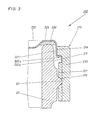
- Fig. 3 eine weitere Ausführungsform eines auf einen Behälterhals aufgesetzten Drehverschlusses in einer senkrecht geschnittenen Teildarstellung, und
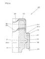
- Fig. 4 eine weitere Ausführungsform eines auf einen Behälterhals aufgesetzten Drehverschlusses in einer senkrecht geschnittenen Teildarstellung.
- In Fig.1 ist ein Drehverschluß 100 dargestellt, der aus einem Schraubring 10 und einem Deckelteil 20 besteht und mit dem die Mündung eines Behälterhalses eines in der Zeichnung nicht dargestellten Behälter 50 verschlossen wird.
- Der Schraubring 10, der aus einem formbaren Kunststoff, z.B. aus Polypropylen, besteht, weist in seinem unteren Bereich nach innen gerichtete Gewindesegmente 40 auf, die in entsprechende Gewindesegmente 51 auf der Außenseite des Behälterhalses eingreifbar sind, um eine Schraubverbindung zu ermöglichen.
- Der Deckel 20 besteht aus Blech, vorzugsweise aus verformbarem Aluminiumblech, und weist eine etwa tellerförmige Form auf, die aus einem Verschlußteil 25 mit einem sich daran anschließenden nach unten offenen Dichtungskanal 26, in dem der Dichtungsring bzw. die Dichtungsmasse 30 angeordnet ist, die auf die oberen Stirnfläche 50a des Behälterhalses des Behälters 50 dichtend auflegbar ist. An den Dichtungskanal 26 schließt sich ein nach unten abgebogener Ringteil an, das aus einem Abschnitt 21a u.b besteht, in dem eine nach aussen umlaufende Sicke 22 ausgebildet ist, die in ein als Ringnut 11 ausgebildetes Gegenstück 60 eingreift.
- Bei der in Fig. 2 dargestellten Ausführungsform 200 weist der Deckel 120 ein an den Dichtungskanal 126 anschließendes nach unten verformten Ringteil 121 auf, an dessen unterem Ende ein Eingreifteil 122 angeordnet ist, das aus einer einen kreisförmigen Querschnitt aufweisenden Bördelung oder Rollierung besteht und in eine im Schraubring 110 ausgebildete Ringnut 111 eingreift. Der Schraubring 110 ist mit einem senkrechten Zentrierungsabschnitt 116 versehen, an die sich eine Winkelsicke anschließt, die als Ringnut mit konischen Einlaufflanken ausgebildet ist.
- Bei einem Aufschrauben des Schraubringes 110 auf den Behälterhals des Behälters 50 wird über die Ringnut 111 und das Eingreifteil 122 der Deckelteil 120 auf den Behälterhals gezogen, so daß über die Dichtungsmasse 130 eine sichere Abdichtung auch bei Unplanheiten des Behälterhalses gewährleistet ist. Da die Ringnut 111 und das Eingreifteil 122 sich entsprechende Formgebungen aufweisen, ist eine spielfreie formschlüssige Verbindung 160 des Deckelteils 120 im Schraubring 110 gewährleistet.
- Unterhalb der Ringnut 111 ist der Zentrierring 112 angeordnet, der auch aus Ringsementen bestehen kann. Der Zentrierring 112 ist dabei in seinem Innen- bzw. Anlageflächendurchmesser D2 so bemessen, daß er den Schraubring 110 und damit den Drehverschluß 200 auf dem Behälterhals zentriert. Hierdurch ist es möglich, trotz der aus fertigungstechnischen Gründen vorzusehenden Toleranzen zwischen den schraubringseitigen und behälterhalsseitigen Gewindesegmenten ein hohes Aufschraub- bzw. Zudrehmoment aufzubringen, ohne daß die Gefahr eines gegenseitigen Wegdrückens der Gewindesegmente auftritt.
- Das Einbringen des Blechdeckels in den Schraubring wird dadurch erreicht. daß die Rollierung unterbrochen werden kann und somit nach innen elastisch ausweichen kann und dann in die Eingreifform einschnappt. Durch starkes Zudrehen oder auch Aufdrehen kann zwar die Rollierung bis an die Behälterwandung ausweichen, bleibt aber kraftschlüssig verbunden.
- Bei der in Fig.3 dargestellten Ausführungsform des Drehverschlusses 300 weist der Deckelteil 220 die gleichen Grundelemente auf, wie diese voranstehend beschrieben wurden. Jedoch schließt sich an den Dichtungskanal 226 ein sich nach unten abgebogener Ringteil 221 an, an dem als Eingreifteil eine nach außen versetzte Stufe, bestehend aus einem Flansch 222a und daran wird ein senkrechter Teil 222b angeordnet, der in eine im Schraubring ausgebildete Ringnut 211 eingreift, die das formschlüssige Gegenstück 260 des Schraubringes 210 bildet.
- Der Schraubring weist dabei einen dem Ringteil 121 gegenüberliegenden Zentrierungsabschnitt 216 auf, an den sich die Ringnut 211 und darauf folgend ein Halterungsabschnitt 217 anschließt, wobei in dem Halterungsabschnitt 217 ein Gewinde 218 eingeschnitten ist, in das entsprechende Gewindesegmente 51 auf der Außenseite des Behälterhalses des Behälters 50 eingreifbar sind, um eine Schraubverbindung zu ermöglichen.
- Bei der in Fig. 4 dargestellten Ausführungsform des Drehverschlusses 400 weist der Deckelteil 320;320ʹ die gleichen Grundelemente auf, wie diese voranstehend beschrieben wurden. An den Dichtungskanal 316;316ʹ schließt der Ringteil mit einem relativ langen 321a bzw. bei der gestrichelt angedeuteten Ausführungsform ein relativ kurzen Abschnitt 321aʹ an, wobei an dem Abschnitt 321a;321aʹ ein nach außen versetzter Umgreifungsabschnitt 321b angeschlossen ist, der einen rechteckförmigen und dem Außenprofil des Schraubringes 310 entsprechenden Querschnitt aufweist und an seinem unteren Ende mit einem zur Halterung des Schraubringes nach Aufnahme des umgebo genen Abschnitt 321c versehen ist.
- Der Schraubring 310 ist dabei als einfache Ringeinlage ausgebildet, in dessen Halterungsabschnitt 311 ein Gewinde 312 eingeschnitten ist, in das entsprechende Gewindesegmente 51 auf der Außenseite des Behälterhalses des Behälters 50 eingreifbar sind, um eine Schraubverbindung zu ermöglichen.
- Alle voranstehend beschriebenen Ausführungsformen des Drehverschlusses sind um eine in der Zeichnung nicht dargestellte Vertikalmittelachse im wesentlichen rotationssymmetrisch ausgebildet. Diese Ausbildung eines Drehverschlusses, bei der der Deckelteil nicht konzentrisch auf die Behältermündung gedrückt wird, sondern seitlich oder innerhalb partiell gezogen wird, was durch den plastischen Schraubring ermöglicht wird, stellt eine sinnvolle Ergänzung eines Behälters dar, wenn dieser aus einem Werkstoff wie Glas besteht.
Claims (6)
Priority Applications (1)
| Application Number | Priority Date | Filing Date | Title |
|---|---|---|---|
| AT88100596T ATE74861T1 (de) | 1987-01-18 | 1988-01-18 | Drehverschluss fuer behaelter. |
Applications Claiming Priority (2)
| Application Number | Priority Date | Filing Date | Title |
|---|---|---|---|
| DE8700722U DE8700722U1 (de) | 1987-01-18 | 1987-01-18 | Drehverschluß für Behälter |
| DE8700722U | 1987-01-18 |
Publications (2)
| Publication Number | Publication Date |
|---|---|
| EP0280024A1 true EP0280024A1 (de) | 1988-08-31 |
| EP0280024B1 EP0280024B1 (de) | 1992-04-15 |
Family
ID=6803686
Family Applications (1)
| Application Number | Title | Priority Date | Filing Date |
|---|---|---|---|
| EP88100596A Expired - Lifetime EP0280024B1 (de) | 1987-01-18 | 1988-01-18 | Drehverschluss für Behälter |
Country Status (6)
| Country | Link |
|---|---|
| EP (1) | EP0280024B1 (de) |
| AT (1) | ATE74861T1 (de) |
| DE (2) | DE8700722U1 (de) |
| DK (1) | DK165585C (de) |
| ES (1) | ES2030767T3 (de) |
| GR (1) | GR3004392T3 (de) |
Cited By (4)
| Publication number | Priority date | Publication date | Assignee | Title |
|---|---|---|---|---|
| EP0445910A1 (de) * | 1990-03-07 | 1991-09-11 | Continental White Cap, Inc. | Verschlussanordnung mit Originalitätsvorrichtung |
| EP0447021A3 (en) * | 1990-03-15 | 1991-12-27 | Continental White Cap, Inc. | Improved composite cap including tamper indicating band |
| US5103991A (en) * | 1990-03-10 | 1992-04-14 | Cmb Foodcan Plc | Screw closures for containers |
| WO2003064276A3 (en) * | 2002-01-31 | 2004-02-05 | Crown Cork & Seal Tech Corp | Composite closure having disk tightening feature |
Citations (7)
| Publication number | Priority date | Publication date | Assignee | Title |
|---|---|---|---|---|
| US3411651A (en) * | 1966-10-31 | 1968-11-19 | Owens Illinois Inc | Barrier for closures |
| DE2334666A1 (de) * | 1972-09-05 | 1974-03-14 | Continental Can Co | Faelschungssicherer verschluss fuer behaelter |
| GB2040891A (en) * | 1979-01-26 | 1980-09-03 | Baxter Travenol Lab | Resealable container |
| US4227618A (en) * | 1979-06-21 | 1980-10-14 | The Continental Group, Inc. | Expansion section for tamper-indicating ring of squeeze-off closure |
| DE2226906B2 (de) * | 1971-06-14 | 1980-12-04 | Anchor Hocking Corp., Lancaster, Ohio (V.St.A.) | Behälterverschlußkappe |
| DE3322326A1 (de) * | 1983-06-21 | 1985-01-03 | Continental White Cap, Inc., Northbrook, Ill. | Drehverschluss fuer behaelter |
| US4560076A (en) * | 1984-04-17 | 1985-12-24 | Continental White Cap, Inc. | Tamper indicating band for use in low rise cam-off application |
-
1987
- 1987-01-18 DE DE8700722U patent/DE8700722U1/de not_active Expired
-
1988
- 1988-01-18 DK DK019788A patent/DK165585C/da active
- 1988-01-18 ES ES198888100596T patent/ES2030767T3/es not_active Expired - Lifetime
- 1988-01-18 AT AT88100596T patent/ATE74861T1/de not_active IP Right Cessation
- 1988-01-18 EP EP88100596A patent/EP0280024B1/de not_active Expired - Lifetime
- 1988-01-18 DE DE8888100596T patent/DE3869993D1/de not_active Expired - Lifetime
-
1992
- 1992-04-16 GR GR920400706T patent/GR3004392T3/el unknown
Patent Citations (7)
| Publication number | Priority date | Publication date | Assignee | Title |
|---|---|---|---|---|
| US3411651A (en) * | 1966-10-31 | 1968-11-19 | Owens Illinois Inc | Barrier for closures |
| DE2226906B2 (de) * | 1971-06-14 | 1980-12-04 | Anchor Hocking Corp., Lancaster, Ohio (V.St.A.) | Behälterverschlußkappe |
| DE2334666A1 (de) * | 1972-09-05 | 1974-03-14 | Continental Can Co | Faelschungssicherer verschluss fuer behaelter |
| GB2040891A (en) * | 1979-01-26 | 1980-09-03 | Baxter Travenol Lab | Resealable container |
| US4227618A (en) * | 1979-06-21 | 1980-10-14 | The Continental Group, Inc. | Expansion section for tamper-indicating ring of squeeze-off closure |
| DE3322326A1 (de) * | 1983-06-21 | 1985-01-03 | Continental White Cap, Inc., Northbrook, Ill. | Drehverschluss fuer behaelter |
| US4560076A (en) * | 1984-04-17 | 1985-12-24 | Continental White Cap, Inc. | Tamper indicating band for use in low rise cam-off application |
Cited By (5)
| Publication number | Priority date | Publication date | Assignee | Title |
|---|---|---|---|---|
| EP0445910A1 (de) * | 1990-03-07 | 1991-09-11 | Continental White Cap, Inc. | Verschlussanordnung mit Originalitätsvorrichtung |
| AU631048B2 (en) * | 1990-03-07 | 1992-11-12 | Continental White Cap, Inc. | Composite cap including tamper indicating feature |
| US5103991A (en) * | 1990-03-10 | 1992-04-14 | Cmb Foodcan Plc | Screw closures for containers |
| EP0447021A3 (en) * | 1990-03-15 | 1991-12-27 | Continental White Cap, Inc. | Improved composite cap including tamper indicating band |
| WO2003064276A3 (en) * | 2002-01-31 | 2004-02-05 | Crown Cork & Seal Tech Corp | Composite closure having disk tightening feature |
Also Published As
| Publication number | Publication date |
|---|---|
| EP0280024B1 (de) | 1992-04-15 |
| GR3004392T3 (de) | 1993-03-31 |
| DE3869993D1 (de) | 1992-05-21 |
| DE8700722U1 (de) | 1987-02-26 |
| DK19788A (da) | 1988-07-19 |
| DK165585B (da) | 1992-12-21 |
| ES2030767T3 (es) | 1992-11-16 |
| ATE74861T1 (de) | 1992-05-15 |
| DK19788D0 (da) | 1988-01-18 |
| DK165585C (da) | 1993-05-03 |
Similar Documents
| Publication | Publication Date | Title |
|---|---|---|
| DE2226906C3 (de) | Behälterverschlußkappe | |
| DE3604214C2 (de) | Kabelverschraubung | |
| EP0048931B1 (de) | Ausgiesser für flaschenartige Behälter | |
| DE3336908A1 (de) | Originalitaetsverschluss aus kunststoff | |
| EP0202506B1 (de) | Behälterverschluss | |
| DE3100956A1 (de) | "behaelterverschluss" | |
| DE102004023796A1 (de) | Dose | |
| DE2251563B2 (de) | Verschlußeinrichtung für ein Behälterende mit einem Verschlußdeckel | |
| EP0280024A1 (de) | Drehverschluss für Behälter | |
| EP0026284B1 (de) | Sicherheitsschraubverschluss | |
| DE69400760T2 (de) | Irreversible abschraubbare Verschlussvorrichtung | |
| CH624073A5 (en) | Closure device for bottles, jugs and similar containers | |
| DE3322326A1 (de) | Drehverschluss fuer behaelter | |
| EP0297160A1 (de) | Kindersicherer Schraubverschluss | |
| EP1077883A1 (de) | Verschlusskappe für gewindehalsflaschen | |
| DE3108518C2 (de) | ||
| DE4135109C2 (de) | Schraubkappe | |
| DE29601568U1 (de) | Flaschenverschluß | |
| DE9418851U1 (de) | Zylindrischer Behälter mit Deckel | |
| EP0212139B1 (de) | Dose | |
| WO1989010313A1 (fr) | Procede de montage de couvercles en plastique | |
| DE3336117A1 (de) | Kappe fuer flaschen, flaeschchen oder sonstige eine fluessigkeit aufnehmenden behaeltern mit einem reduzierdeckel zur reduzierung der urspruenglichen bzw. normalen oeffnung der flasche od. dgl. | |
| DE4216945A1 (de) | Verschlußkappe mit Originalitäts-Sicherungselement | |
| EP0757652B1 (de) | Verschluss für ein rohrförmiges element | |
| DE2614335A1 (de) | Verschluss |
Legal Events
| Date | Code | Title | Description |
|---|---|---|---|
| PUAI | Public reference made under article 153(3) epc to a published international application that has entered the european phase |
Free format text: ORIGINAL CODE: 0009012 |
|
| AK | Designated contracting states |
Kind code of ref document: A1 Designated state(s): AT BE CH DE ES FR GB GR IT LI LU NL SE |
|
| 17P | Request for examination filed |
Effective date: 19890209 |
|
| 17Q | First examination report despatched |
Effective date: 19900904 |
|
| ITF | It: translation for a ep patent filed | ||
| GRAA | (expected) grant |
Free format text: ORIGINAL CODE: 0009210 |
|
| AK | Designated contracting states |
Kind code of ref document: B1 Designated state(s): AT BE CH DE ES FR GB GR IT LI LU NL SE |
|
| REF | Corresponds to: |
Ref document number: 74861 Country of ref document: AT Date of ref document: 19920515 Kind code of ref document: T |
|
| ET | Fr: translation filed | ||
| REF | Corresponds to: |
Ref document number: 3869993 Country of ref document: DE Date of ref document: 19920521 |
|
| GBT | Gb: translation of ep patent filed (gb section 77(6)(a)/1977) | ||
| REG | Reference to a national code |
Ref country code: ES Ref legal event code: FG2A Ref document number: 2030767 Country of ref document: ES Kind code of ref document: T3 |
|
| REG | Reference to a national code |
Ref country code: GR Ref legal event code: FG4A Free format text: 3004392 |
|
| PLBE | No opposition filed within time limit |
Free format text: ORIGINAL CODE: 0009261 |
|
| STAA | Information on the status of an ep patent application or granted ep patent |
Free format text: STATUS: NO OPPOSITION FILED WITHIN TIME LIMIT |
|
| 26N | No opposition filed | ||
| EPTA | Lu: last paid annual fee | ||
| PGFP | Annual fee paid to national office [announced via postgrant information from national office to epo] |
Ref country code: BE Payment date: 19950111 Year of fee payment: 8 |
|
| EAL | Se: european patent in force in sweden |
Ref document number: 88100596.1 |
|
| PGFP | Annual fee paid to national office [announced via postgrant information from national office to epo] |
Ref country code: LU Payment date: 19960101 Year of fee payment: 9 |
|
| PGFP | Annual fee paid to national office [announced via postgrant information from national office to epo] |
Ref country code: GR Payment date: 19960117 Year of fee payment: 9 |
|
| PG25 | Lapsed in a contracting state [announced via postgrant information from national office to epo] |
Ref country code: BE Effective date: 19960131 |
|
| BERE | Be: lapsed |
Owner name: EBERHARDT HEINRICH Effective date: 19960131 |
|
| PGFP | Annual fee paid to national office [announced via postgrant information from national office to epo] |
Ref country code: SE Payment date: 19961204 Year of fee payment: 10 |
|
| PG25 | Lapsed in a contracting state [announced via postgrant information from national office to epo] |
Ref country code: LU Free format text: LAPSE BECAUSE OF NON-PAYMENT OF DUE FEES Effective date: 19970118 |
|
| PG25 | Lapsed in a contracting state [announced via postgrant information from national office to epo] |
Ref country code: GR Free format text: THE PATENT HAS BEEN ANNULLED BY A DECISION OF A NATIONAL AUTHORITY Effective date: 19970731 |
|
| REG | Reference to a national code |
Ref country code: GR Ref legal event code: MM2A Free format text: 3004392 |
|
| PGFP | Annual fee paid to national office [announced via postgrant information from national office to epo] |
Ref country code: CH Payment date: 19971217 Year of fee payment: 11 |
|
| PGFP | Annual fee paid to national office [announced via postgrant information from national office to epo] |
Ref country code: AT Payment date: 19971230 Year of fee payment: 11 |
|
| PG25 | Lapsed in a contracting state [announced via postgrant information from national office to epo] |
Ref country code: SE Free format text: LAPSE BECAUSE OF NON-PAYMENT OF DUE FEES Effective date: 19980119 |
|
| PGFP | Annual fee paid to national office [announced via postgrant information from national office to epo] |
Ref country code: NL Payment date: 19980130 Year of fee payment: 11 |
|
| PGFP | Annual fee paid to national office [announced via postgrant information from national office to epo] |
Ref country code: ES Payment date: 19980416 Year of fee payment: 11 |
|
| EUG | Se: european patent has lapsed |
Ref document number: 88100596.1 |
|
| PG25 | Lapsed in a contracting state [announced via postgrant information from national office to epo] |
Ref country code: AT Free format text: LAPSE BECAUSE OF NON-PAYMENT OF DUE FEES Effective date: 19990118 |
|
| PG25 | Lapsed in a contracting state [announced via postgrant information from national office to epo] |
Ref country code: ES Free format text: THE PATENT HAS BEEN ANNULLED BY A DECISION OF A NATIONAL AUTHORITY Effective date: 19990119 |
|
| PG25 | Lapsed in a contracting state [announced via postgrant information from national office to epo] |
Ref country code: LI Free format text: LAPSE BECAUSE OF NON-PAYMENT OF DUE FEES Effective date: 19990131 Ref country code: CH Free format text: LAPSE BECAUSE OF NON-PAYMENT OF DUE FEES Effective date: 19990131 |
|
| PG25 | Lapsed in a contracting state [announced via postgrant information from national office to epo] |
Ref country code: NL Free format text: LAPSE BECAUSE OF NON-PAYMENT OF DUE FEES Effective date: 19990801 |
|
| REG | Reference to a national code |
Ref country code: CH Ref legal event code: PL |
|
| PGFP | Annual fee paid to national office [announced via postgrant information from national office to epo] |
Ref country code: FR Payment date: 19991217 Year of fee payment: 13 |
|
| PGFP | Annual fee paid to national office [announced via postgrant information from national office to epo] |
Ref country code: GB Payment date: 19991220 Year of fee payment: 13 |
|
| PGFP | Annual fee paid to national office [announced via postgrant information from national office to epo] |
Ref country code: DE Payment date: 20000321 Year of fee payment: 13 |
|
| PG25 | Lapsed in a contracting state [announced via postgrant information from national office to epo] |
Ref country code: GB Free format text: LAPSE BECAUSE OF NON-PAYMENT OF DUE FEES Effective date: 20010118 |
|
| REG | Reference to a national code |
Ref country code: ES Ref legal event code: FD2A Effective date: 20010604 |
|
| GBPC | Gb: european patent ceased through non-payment of renewal fee |
Effective date: 20010118 |
|
| PG25 | Lapsed in a contracting state [announced via postgrant information from national office to epo] |
Ref country code: FR Free format text: LAPSE BECAUSE OF NON-PAYMENT OF DUE FEES Effective date: 20010928 |
|
| PG25 | Lapsed in a contracting state [announced via postgrant information from national office to epo] |
Ref country code: DE Free format text: LAPSE BECAUSE OF NON-PAYMENT OF DUE FEES Effective date: 20011101 |
|
| REG | Reference to a national code |
Ref country code: FR Ref legal event code: ST |
|
| PG25 | Lapsed in a contracting state [announced via postgrant information from national office to epo] |
Ref country code: IT Free format text: LAPSE BECAUSE OF NON-PAYMENT OF DUE FEES;WARNING: LAPSES OF ITALIAN PATENTS WITH EFFECTIVE DATE BEFORE 2007 MAY HAVE OCCURRED AT ANY TIME BEFORE 2007. THE CORRECT EFFECTIVE DATE MAY BE DIFFERENT FROM THE ONE RECORDED. Effective date: 20050118 |