EP0280034A2 - Axe et barre pour un segment d'arrêt de tuyère - Google Patents
Axe et barre pour un segment d'arrêt de tuyère Download PDFInfo
- Publication number
- EP0280034A2 EP0280034A2 EP88100783A EP88100783A EP0280034A2 EP 0280034 A2 EP0280034 A2 EP 0280034A2 EP 88100783 A EP88100783 A EP 88100783A EP 88100783 A EP88100783 A EP 88100783A EP 0280034 A2 EP0280034 A2 EP 0280034A2
- Authority
- EP
- European Patent Office
- Prior art keywords
- bolt
- pin
- keeper
- bore
- assembly
- Prior art date
- Legal status (The legal status is an assumption and is not a legal conclusion. Google has not performed a legal analysis and makes no representation as to the accuracy of the status listed.)
- Granted
Links
Images


Classifications
-
- G—PHYSICS
- G21—NUCLEAR PHYSICS; NUCLEAR ENGINEERING
- G21D—NUCLEAR POWER PLANT
- G21D1/00—Details of nuclear power plant
-
- F—MECHANICAL ENGINEERING; LIGHTING; HEATING; WEAPONS; BLASTING
- F16—ENGINEERING ELEMENTS AND UNITS; GENERAL MEASURES FOR PRODUCING AND MAINTAINING EFFECTIVE FUNCTIONING OF MACHINES OR INSTALLATIONS; THERMAL INSULATION IN GENERAL
- F16B—DEVICES FOR FASTENING OR SECURING CONSTRUCTIONAL ELEMENTS OR MACHINE PARTS TOGETHER, e.g. NAILS, BOLTS, CIRCLIPS, CLAMPS, CLIPS OR WEDGES; JOINTS OR JOINTING
- F16B5/00—Joining sheets or plates, e.g. panels, to one another or to strips or bars parallel to them
- F16B5/10—Joining sheets or plates, e.g. panels, to one another or to strips or bars parallel to them by means of bayonet connections
-
- F—MECHANICAL ENGINEERING; LIGHTING; HEATING; WEAPONS; BLASTING
- F16—ENGINEERING ELEMENTS AND UNITS; GENERAL MEASURES FOR PRODUCING AND MAINTAINING EFFECTIVE FUNCTIONING OF MACHINES OR INSTALLATIONS; THERMAL INSULATION IN GENERAL
- F16L—PIPES; JOINTS OR FITTINGS FOR PIPES; SUPPORTS FOR PIPES, CABLES OR PROTECTIVE TUBING; MEANS FOR THERMAL INSULATION IN GENERAL
- F16L55/00—Devices or appurtenances for use in, or in connection with, pipes or pipe systems
- F16L55/10—Means for stopping flow in pipes or hoses
-
- F—MECHANICAL ENGINEERING; LIGHTING; HEATING; WEAPONS; BLASTING
- F22—STEAM GENERATION
- F22B—METHODS OF STEAM GENERATION; STEAM BOILERS
- F22B37/00—Component parts or details of steam boilers
- F22B37/02—Component parts or details of steam boilers applicable to more than one kind or type of steam boiler
- F22B37/22—Drums; Headers; Accessories therefor
- F22B37/221—Covers for drums, collectors, manholes or the like
- F22B37/222—Nozzle dams introduced through a smaller manway, e.g. foldable
-
- G—PHYSICS
- G21—NUCLEAR PHYSICS; NUCLEAR ENGINEERING
- G21D—NUCLEAR POWER PLANT
- G21D5/00—Arrangements of reactor and engine in which reactor-produced heat is converted into mechanical energy
- G21D5/04—Reactor and engine not structurally combined
- G21D5/08—Reactor and engine not structurally combined with engine working medium heated in a heat exchanger by the reactor coolant
-
- Y—GENERAL TAGGING OF NEW TECHNOLOGICAL DEVELOPMENTS; GENERAL TAGGING OF CROSS-SECTIONAL TECHNOLOGIES SPANNING OVER SEVERAL SECTIONS OF THE IPC; TECHNICAL SUBJECTS COVERED BY FORMER USPC CROSS-REFERENCE ART COLLECTIONS [XRACs] AND DIGESTS
- Y02—TECHNOLOGIES OR APPLICATIONS FOR MITIGATION OR ADAPTATION AGAINST CLIMATE CHANGE
- Y02E—REDUCTION OF GREENHOUSE GAS [GHG] EMISSIONS, RELATED TO ENERGY GENERATION, TRANSMISSION OR DISTRIBUTION
- Y02E30/00—Energy generation of nuclear origin
-
- Y—GENERAL TAGGING OF NEW TECHNOLOGICAL DEVELOPMENTS; GENERAL TAGGING OF CROSS-SECTIONAL TECHNOLOGIES SPANNING OVER SEVERAL SECTIONS OF THE IPC; TECHNICAL SUBJECTS COVERED BY FORMER USPC CROSS-REFERENCE ART COLLECTIONS [XRACs] AND DIGESTS
- Y10—TECHNICAL SUBJECTS COVERED BY FORMER USPC
- Y10T—TECHNICAL SUBJECTS COVERED BY FORMER US CLASSIFICATION
- Y10T292/00—Closure fasteners
- Y10T292/08—Bolts
- Y10T292/0863—Sliding and rotary
- Y10T292/0866—Multiple head
-
- Y—GENERAL TAGGING OF NEW TECHNOLOGICAL DEVELOPMENTS; GENERAL TAGGING OF CROSS-SECTIONAL TECHNOLOGIES SPANNING OVER SEVERAL SECTIONS OF THE IPC; TECHNICAL SUBJECTS COVERED BY FORMER USPC CROSS-REFERENCE ART COLLECTIONS [XRACs] AND DIGESTS
- Y10—TECHNICAL SUBJECTS COVERED BY FORMER USPC
- Y10T—TECHNICAL SUBJECTS COVERED BY FORMER US CLASSIFICATION
- Y10T292/00—Closure fasteners
- Y10T292/08—Bolts
- Y10T292/0863—Sliding and rotary
- Y10T292/0867—Spring projected
- Y10T292/0868—Combined motion
Definitions
- the present invention relates to an improvement in nozzle dams for steam generators of the type in association with a conventional nuclear power generating system.
- Nozzle dams are used to provide a temporary liquid tight seal in a nozzle of a steam generator to isolate the generator from the nuclear reactor with which it is associated.
- the improved nozzle dam bolt assembly and keeper member of the invention are permanently attached to the nozzle dam segments by a press fit.
- a close tolerance hole drilled in each boss of the dam segments has either a cylindrical body portion of the bolt assembly or of the keeper member pressed into the hole to form the pressed fit.
- Nuclear steam generator isolation dams normally are made up of two or three segments and, therefore, there are typically one or two such bolted joints in a dam with each joint typically having three bolt assembly and keeper member combinations.
- the bolt assembly includes an elongated bolt body having an outer dam segment engaging surface portion.
- An axial bore is provided in the bolt body and, typically, will include a first enlarged diameter bore portion at one end of the bore and a second and reduced diameter bore portion at the opposite end of the bore.
- An elongated bolt pin is slidably mounted in the bore and includes a first enlarged diameter pin portion in slidable engagement with the first enlarged diameter bore portion.
- a second and reduced diameter portion at the opposite end of the pin is in slidable engagement with the second and reduced diameter bore portion.
- a spring for biasing the bolt pin toward a position of projection from the end of the bolt body bore portion in the direction of the keeper surrounds the pin within the bolt body.
- a lever within an axially directed slot is provided to secure the bolt pin in a position of retraction within the bolt bore against the spring urging.
- the keeper member of the combination includes an elongated keeper body having a dam segment engaging surface portion and an axial bore for receiving the bolt pin of the adjacent dam segment.
- the bolt pin is provided with a transverse projection on the end adjacent the keeper member.
- a slot parallel to the bore is in open communication with it for receiving the transverse projection as the bolt pin is slidably received in the keeper body axial bore.
- the keeper body and the bolt pin are proportioned to permit the transverse projection to pass to the end of the slot and be rotated into engagement with the end of the keeper body opposite the bolt assembly.
- a second biasing means in the form of a rubber washer mounted on the exterior of the bolt body acts against the force of the spring to hold the transverse projection against the end of the keeper body opposite the bolt pin assembly.
- the end of the keeper body against which the transverse projection rides includes a cam ramp for guiding the rotated bolt pin transverse projection to a position of securement in a recess in the end of the keeper body.
- the bolt assembly and keeper member have two transverse projections, two slots, two ramps, and two recesses in the end of the keeper body symetrically arranged on opposite sides of the bore.
- the recess in the end of the keeper body is tapered to provide a guiding notch.
- the slot is also provided with a tapered entry surface in the form of a V-notch to guide the transverse projection into the slot of the keeper body.
- the rubber washer on the exterior of the bolt assembly body is compressed by means of a lever secured to the bolt pin and extended outwardly through the transverse slot in the bolt assembly body communicating the bolt pin bore with the outside of the body.
- the transverse slot has an axial portion sufficient in length to permit axial travel of the lever as the bolt pin moves axially to project or to retract and the slot further includes two spaced circumferential portions sufficient in length to permit rotational travel of the lever and bolt pin to positions which prevent axial travel of the lever and bolt pin for securing the bolt pin in either retracted position or in locked position for securing the segments together.
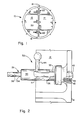
- the numeral 10 generally designates a nuclear steam generator isolation dam made up of assembled segments 12 and 14.
- the dam 10 is shown as being made up of these two segments for illustration purposes, but it should be realized that nozzle dams of larger size are often made to include more than two segments.
- Each combination 20 includes a bolt assembly generally designated 22 and a keeper member generally designated 24.
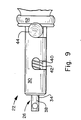
- the bolt assembly 22 includes a pin 26 slidably mounted in an elongated body 30.
- the elongated body 30 has an outer cylindrical dam engaging surface portion and a central axial bore made up of a first enlarged diameter portion 32 at one of the end bore and a second and reduced diameter bore portion 34 at the opposite end of the bore.
- the elongated pin 26 slidably mounted in the bore includes a first enlarged diameter pin portion 36 and a second and reduced diameter pin portion 38.
- a shoulder (not seen) lies between pin portions 36 and 38.
- the enlarged diameter pin portion 36 rides in the first enlarged diameter bore portion 32 and the second and reduced diameter pin portion 38, at the opposite end of the pin 26 is slidably mounted within the reduced diameter bore portion 34.
- a compression spring means 42 within chamber 40 surrounds the reduced diameter pin portion 38 and biases the pin 26 toward a position of projection from the end of body 30 adjacent its large diameter bore portion 32.
- the projecting pin portion 26 has a tapered surface 43 on its end. Adjacent the tapered surface 43 is a transverse pin 45 which projects from opposite points onthe surface of pin portion 36.
- the body 30 of the bolt pin assembly 22 includes a transverse slot 31 which communicates the bore portion 32 with the outside of the body.
- a lever or handle 44 which for ease of assembly and manufacture may be threadedly secured to the pin 26, extends outwardly through the slot 31.
- the keeper member 24 is a stainless steel hollow body press fit into the dam segment 14 with its axial bore 40 normal to the surface 18 of the dam segment.
- the keeper member 24 has one end flush with the surface 18 of the segment 14 and an opposite end which extends beyond the boss 14A of dam segment 14 into which it is press fit.
- the bore 40 of the keeper member 24 is in open communication with slots 46 and 48 parallel to the bore 40 for receiving the projecting ends 45 of the transverse pin as the bolt pin 26 is received in the keeper body 24 axial bore 40.
- the keeper body 24 and the bolt pin 26 are proportioned to permit the transverse projections 45 to pass the end of the slots 46 and 48 and be rotated into engagement with the end of the keeper body 24.
- cam ramp 50 guides the rotated bolt pin against the urging of a rubber washer 52, outwardly, until it reaches the recess 54 which is a V-notch in which the transverse pin 45 will seat in a position of securement, where it is held by the urging of the rubber washer 52 as seen in Figure 8.
- the ends of the transverse pin 45 are accommodated as the bolt pin 26 is moved to its fully retracted position by short slots 56 which are parallel to and in open communication with the enlarged bore portion 32 of the bolt body 30.
- a V-notch 58 guides the ends 45 of the transverse pin into the slots 46 and 48, thus defining a tapered entry surface in the keeper body end adjacent to the bolt assembly 22.
- the new and improved bolt assembly and keeper member combination is provided which accomplishes the objective of providing a faster assembly of the nozzle dam segments while reducing the overall weight of the nozzle dam. This is accomplished by means which are attached permanently to the nozzle dam.
Landscapes
- Engineering & Computer Science (AREA)
- General Engineering & Computer Science (AREA)
- Mechanical Engineering (AREA)
- Physics & Mathematics (AREA)
- Thermal Sciences (AREA)
- Plasma & Fusion (AREA)
- High Energy & Nuclear Physics (AREA)
- Turbine Rotor Nozzle Sealing (AREA)
- Monitoring And Testing Of Nuclear Reactors (AREA)
- Financial Or Insurance-Related Operations Such As Payment And Settlement (AREA)
Applications Claiming Priority (2)
| Application Number | Priority Date | Filing Date | Title |
|---|---|---|---|
| US19725 | 1987-02-27 | ||
| US07/019,725 US4744392A (en) | 1987-02-27 | 1987-02-27 | Nozzle dam segment bolt and keeper |
Publications (3)
| Publication Number | Publication Date |
|---|---|
| EP0280034A2 true EP0280034A2 (fr) | 1988-08-31 |
| EP0280034A3 EP0280034A3 (en) | 1988-11-30 |
| EP0280034B1 EP0280034B1 (fr) | 1992-07-29 |
Family
ID=21794691
Family Applications (1)
| Application Number | Title | Priority Date | Filing Date |
|---|---|---|---|
| EP88100783A Expired - Lifetime EP0280034B1 (fr) | 1987-02-27 | 1988-01-20 | Axe et barre pour un segment d'arrêt de tuyère |
Country Status (4)
| Country | Link |
|---|---|
| US (1) | US4744392A (fr) |
| EP (1) | EP0280034B1 (fr) |
| KR (1) | KR920000290B1 (fr) |
| ES (1) | ES2033939T3 (fr) |
Families Citing this family (24)
| Publication number | Priority date | Publication date | Assignee | Title |
|---|---|---|---|---|
| US4954312A (en) * | 1988-12-15 | 1990-09-04 | Combustion Engineering, Inc. | Remotely installed steam generator nozzle dam system |
| US5032045A (en) * | 1990-03-30 | 1991-07-16 | The United States Of America As Represented By The Administrator Of The National Aeronautics And Space Administration | Quick action clamp |
| US5169594A (en) * | 1992-01-30 | 1992-12-08 | Combustion Engineering, Inc. | Method of remotely installing or removing a nozzle dam |
| US5275029A (en) * | 1992-07-13 | 1994-01-04 | Fort Lock Corporation | Refrigerator door lock |
| US5564371A (en) * | 1994-05-06 | 1996-10-15 | Foster Miller, Inc. | Upper bundle steam generator cleaning system and method |
| US6672257B1 (en) | 1994-05-06 | 2004-01-06 | Foster-Miller, Inc. | Upper bundle steam generator cleaning system and method |
| US5746455A (en) * | 1996-04-29 | 1998-05-05 | Takigen Manufacturing Co. Ltd. | Gate or door spring-biased bolt latch |
| US6003908A (en) * | 1997-06-17 | 1999-12-21 | King; Richard | Locking device for bird animal cage |
| GB2362919B (en) * | 2000-05-30 | 2004-02-25 | Autoliv Dev | Improvements in or relating to a lock component |
| US9523215B2 (en) * | 2000-11-21 | 2016-12-20 | Triteq Lock And Security, Llc | Electronic locking systems for vending machines and the like |
| US6581986B2 (en) | 2000-11-21 | 2003-06-24 | Tri Teq Lock And Security, L.L.C. | Bayonet locking system and method for vending machines and the like |
| AU2002231151A1 (en) * | 2000-12-21 | 2002-07-01 | Foster-Miller Inc. | Steerable delivery system |
| KR100977521B1 (ko) | 2003-10-27 | 2010-08-23 | 한국항공우주산업 주식회사 | 부품 고정용 스프링 엘 핀 |
| US7044509B2 (en) * | 2004-03-04 | 2006-05-16 | Radel Michael B | Closure latch assembly |
| US7331616B2 (en) * | 2004-07-15 | 2008-02-19 | General Motors Corporation | Hood latch assemblies utilizing active materials and methods of use |
| US7322153B2 (en) * | 2004-08-27 | 2008-01-29 | Nitz Allen S | Baby gate |
| FR2920133B1 (fr) * | 2007-08-20 | 2009-10-30 | Aircelle Sa | Nacelle de turboreacteur, destinee a equiper un aeronef |
| US8670514B2 (en) * | 2007-12-14 | 2014-03-11 | Westinghouse Electric Company Llc | Hatch mechanical locking system |
| US8870243B2 (en) * | 2008-02-28 | 2014-10-28 | Short Go, Inc. | Single-motion mechanically leveraged latch apparatus for horse trailer stall divider |
| DE102011055591A1 (de) * | 2011-11-22 | 2013-05-23 | Pfannenberg Gmbh | Signalgerät zur Aussendung eines akustischen und/oder visuellen Signals |
| US11002039B2 (en) | 2012-04-20 | 2021-05-11 | Triteq Lock And Security, L.L.C. | Electronic controlled handles |
| US8517434B1 (en) * | 2012-06-19 | 2013-08-27 | Richard Thomas Reep, Sr. | Pocket door latch |
| US8708595B2 (en) * | 2012-09-05 | 2014-04-29 | Hanwit Precision Industries Ltd. | Panel member locking device |
| US11083181B2 (en) * | 2019-07-12 | 2021-08-10 | Rocco Nicola Priore | Detachable weight assembly for fishing lure |
Family Cites Families (8)
| Publication number | Priority date | Publication date | Assignee | Title |
|---|---|---|---|---|
| US2843154A (en) * | 1955-06-27 | 1958-07-15 | Hosking Patent Corp | Expansible plug for pipes |
| US3101641A (en) * | 1960-11-04 | 1963-08-27 | Carr Lane Mfg Co | Adjustable ball pin |
| US3255547A (en) * | 1965-01-28 | 1966-06-14 | Grego Inc | Firearm bolt mechanism for firing electric filament primed cartridges |
| US3834422A (en) * | 1973-01-19 | 1974-09-10 | Cherne Ind Inc | Sewer repair apparatus |
| US4482076A (en) * | 1979-02-02 | 1984-11-13 | Combustion Engineering, Inc. | Nozzle plug for submersible vessel |
| US4518015A (en) * | 1982-02-24 | 1985-05-21 | The Presray Corporation | Inflatable plug |
| US4483457A (en) * | 1983-03-31 | 1984-11-20 | Combustion Engineering, Inc. | Hinged steam generator nozzle plug |
| US4619549A (en) * | 1984-11-13 | 1986-10-28 | Builders Equipment And Tool Manufacturing Company | Scaffolding connection apparatus and method |
-
1987
- 1987-02-27 US US07/019,725 patent/US4744392A/en not_active Expired - Fee Related
-
1988
- 1988-01-20 EP EP88100783A patent/EP0280034B1/fr not_active Expired - Lifetime
- 1988-01-20 ES ES198888100783T patent/ES2033939T3/es not_active Expired - Lifetime
- 1988-02-24 KR KR1019880001889A patent/KR920000290B1/ko not_active Expired
Also Published As
| Publication number | Publication date |
|---|---|
| EP0280034B1 (fr) | 1992-07-29 |
| US4744392A (en) | 1988-05-17 |
| KR880010432A (ko) | 1988-10-08 |
| EP0280034A3 (en) | 1988-11-30 |
| KR920000290B1 (ko) | 1992-01-11 |
| ES2033939T3 (es) | 1993-04-01 |
Similar Documents
| Publication | Publication Date | Title |
|---|---|---|
| US4744392A (en) | Nozzle dam segment bolt and keeper | |
| US4915419A (en) | Sliding lock plate for hydraulic connectors | |
| US4483510A (en) | Fast-fit unions for removably joining pipes | |
| US4114853A (en) | Quick connect coupling | |
| US5052849A (en) | Quick-locking connector | |
| US5829480A (en) | Locking device for undersea hydraulic coupling | |
| US6106026A (en) | Locking device for undersea hydraulic coupling | |
| US4171559A (en) | Method of making connections in pneumatic and hydraulic systems and testing such systems | |
| RU2153125C2 (ru) | Быстро соединяемая и разъединяемая муфта, способ и устройство для ее сборки | |
| US4921258A (en) | Adapter seal | |
| US20040134246A1 (en) | Locking cover plate arrangement | |
| GB1581484A (en) | Apparatus for making connections in pneumatic and hydraulic systems | |
| JPS6032000B2 (ja) | 噴出防止ラムロツク装置及び方法 | |
| GB1264890A (fr) | ||
| US4513788A (en) | Flange system for pipeline plugging | |
| US4770235A (en) | Nozzle dam locking pin assembly | |
| US20180230758A1 (en) | Radial Ratchet Dog Anti-Rotation Device | |
| US5026200A (en) | Releasable connector | |
| DE4109100A1 (de) | Dichtring | |
| JP4098895B2 (ja) | 圧力流体取扱設備用安全回路遮断装置 | |
| US5899228A (en) | Undersea hydraulic coupling with locking mechanism | |
| US3079178A (en) | Flush coupling assemblies | |
| US4165891A (en) | Breech block connector | |
| GB2132725A (en) | Automatic hydraulic connectors | |
| DE2623934C3 (de) | Steckkupplung zum Verbinden von Gasleitungen |
Legal Events
| Date | Code | Title | Description |
|---|---|---|---|
| PUAI | Public reference made under article 153(3) epc to a published international application that has entered the european phase |
Free format text: ORIGINAL CODE: 0009012 |
|
| AK | Designated contracting states |
Kind code of ref document: A2 Designated state(s): BE CH ES GB LI SE |
|
| PUAL | Search report despatched |
Free format text: ORIGINAL CODE: 0009013 |
|
| AK | Designated contracting states |
Kind code of ref document: A3 Designated state(s): BE CH ES GB LI SE |
|
| 17P | Request for examination filed |
Effective date: 19890424 |
|
| 17Q | First examination report despatched |
Effective date: 19910531 |
|
| GRAA | (expected) grant |
Free format text: ORIGINAL CODE: 0009210 |
|
| AK | Designated contracting states |
Kind code of ref document: B1 Designated state(s): BE CH ES GB LI SE |
|
| REG | Reference to a national code |
Ref country code: ES Ref legal event code: FG2A Ref document number: 2033939 Country of ref document: ES Kind code of ref document: T3 |
|
| PLBE | No opposition filed within time limit |
Free format text: ORIGINAL CODE: 0009261 |
|
| STAA | Information on the status of an ep patent application or granted ep patent |
Free format text: STATUS: NO OPPOSITION FILED WITHIN TIME LIMIT |
|
| 26N | No opposition filed | ||
| PGFP | Annual fee paid to national office [announced via postgrant information from national office to epo] |
Ref country code: CH Payment date: 19931228 Year of fee payment: 7 |
|
| PGFP | Annual fee paid to national office [announced via postgrant information from national office to epo] |
Ref country code: SE Payment date: 19931230 Year of fee payment: 7 |
|
| PGFP | Annual fee paid to national office [announced via postgrant information from national office to epo] |
Ref country code: GB Payment date: 19940106 Year of fee payment: 7 |
|
| PGFP | Annual fee paid to national office [announced via postgrant information from national office to epo] |
Ref country code: BE Payment date: 19940107 Year of fee payment: 7 |
|
| PGFP | Annual fee paid to national office [announced via postgrant information from national office to epo] |
Ref country code: ES Payment date: 19940629 Year of fee payment: 7 |
|
| PG25 | Lapsed in a contracting state [announced via postgrant information from national office to epo] |
Ref country code: GB Effective date: 19950120 |
|
| PG25 | Lapsed in a contracting state [announced via postgrant information from national office to epo] |
Ref country code: SE Effective date: 19950121 Ref country code: ES Free format text: LAPSE BECAUSE OF NON-PAYMENT OF DUE FEES Effective date: 19950121 |
|
| EAL | Se: european patent in force in sweden |
Ref document number: 88100783.5 |
|
| PG25 | Lapsed in a contracting state [announced via postgrant information from national office to epo] |
Ref country code: LI Effective date: 19950131 Ref country code: CH Effective date: 19950131 Ref country code: BE Effective date: 19950131 |
|
| BERE | Be: lapsed |
Owner name: COMBUSTION ENGINEERING INC. Effective date: 19950131 |
|
| GBPC | Gb: european patent ceased through non-payment of renewal fee |
Effective date: 19950120 |
|
| REG | Reference to a national code |
Ref country code: CH Ref legal event code: PL |
|
| EUG | Se: european patent has lapsed |
Ref document number: 88100783.5 |
|
| REG | Reference to a national code |
Ref country code: ES Ref legal event code: FD2A Effective date: 19990201 |