EP0280049A2 - Palier-bascule - Google Patents
Palier-bascule Download PDFInfo
- Publication number
- EP0280049A2 EP0280049A2 EP88101066A EP88101066A EP0280049A2 EP 0280049 A2 EP0280049 A2 EP 0280049A2 EP 88101066 A EP88101066 A EP 88101066A EP 88101066 A EP88101066 A EP 88101066A EP 0280049 A2 EP0280049 A2 EP 0280049A2
- Authority
- EP
- European Patent Office
- Prior art keywords
- handwheel
- toggle lever
- shaft holder
- closed position
- bearing according
- Prior art date
- Legal status (The legal status is an assumption and is not a legal conclusion. Google has not performed a legal analysis and makes no representation as to the accuracy of the status listed.)
- Granted
Links
Images
Classifications
-
- F—MECHANICAL ENGINEERING; LIGHTING; HEATING; WEAPONS; BLASTING
- F16—ENGINEERING ELEMENTS AND UNITS; GENERAL MEASURES FOR PRODUCING AND MAINTAINING EFFECTIVE FUNCTIONING OF MACHINES OR INSTALLATIONS; THERMAL INSULATION IN GENERAL
- F16D—COUPLINGS FOR TRANSMITTING ROTATION; CLUTCHES; BRAKES
- F16D1/00—Couplings for rigidly connecting two coaxial shafts or other movable machine elements
- F16D1/06—Couplings for rigidly connecting two coaxial shafts or other movable machine elements for attachment of a member on a shaft or on a shaft-end
- F16D1/08—Couplings for rigidly connecting two coaxial shafts or other movable machine elements for attachment of a member on a shaft or on a shaft-end with clamping hub; with hub and longitudinal key
- F16D1/0811—Couplings for rigidly connecting two coaxial shafts or other movable machine elements for attachment of a member on a shaft or on a shaft-end with clamping hub; with hub and longitudinal key with radial clamping due to tilting of a hub part or ring about a diametral axis
-
- B—PERFORMING OPERATIONS; TRANSPORTING
- B65—CONVEYING; PACKING; STORING; HANDLING THIN OR FILAMENTARY MATERIAL
- B65H—HANDLING THIN OR FILAMENTARY MATERIAL, e.g. SHEETS, WEBS, CABLES
- B65H16/00—Unwinding, paying-out webs
- B65H16/02—Supporting web roll
- B65H16/06—Supporting web roll both-ends type
-
- B—PERFORMING OPERATIONS; TRANSPORTING
- B65—CONVEYING; PACKING; STORING; HANDLING THIN OR FILAMENTARY MATERIAL
- B65H—HANDLING THIN OR FILAMENTARY MATERIAL, e.g. SHEETS, WEBS, CABLES
- B65H18/00—Winding webs
- B65H18/02—Supporting web roll
-
- B—PERFORMING OPERATIONS; TRANSPORTING
- B65—CONVEYING; PACKING; STORING; HANDLING THIN OR FILAMENTARY MATERIAL
- B65H—HANDLING THIN OR FILAMENTARY MATERIAL, e.g. SHEETS, WEBS, CABLES
- B65H2301/00—Handling processes for sheets or webs
- B65H2301/40—Type of handling process
- B65H2301/41—Winding, unwinding
- B65H2301/413—Supporting web roll
- B65H2301/4136—Mounting arrangements not otherwise provided for
- B65H2301/41366—Mounting arrangements not otherwise provided for arrangements for mounting and supporting and -preferably- driving the (un)winding shaft
- B65H2301/413665—Mounting arrangements not otherwise provided for arrangements for mounting and supporting and -preferably- driving the (un)winding shaft articulated bearing
-
- Y—GENERAL TAGGING OF NEW TECHNOLOGICAL DEVELOPMENTS; GENERAL TAGGING OF CROSS-SECTIONAL TECHNOLOGIES SPANNING OVER SEVERAL SECTIONS OF THE IPC; TECHNICAL SUBJECTS COVERED BY FORMER USPC CROSS-REFERENCE ART COLLECTIONS [XRACs] AND DIGESTS
- Y10—TECHNICAL SUBJECTS COVERED BY FORMER USPC
- Y10T—TECHNICAL SUBJECTS COVERED BY FORMER US CLASSIFICATION
- Y10T403/00—Joints and connections
- Y10T403/59—Manually releaseable latch type
- Y10T403/591—Manually releaseable latch type having operating mechanism
- Y10T403/593—Remotely actuated
-
- Y—GENERAL TAGGING OF NEW TECHNOLOGICAL DEVELOPMENTS; GENERAL TAGGING OF CROSS-SECTIONAL TECHNOLOGIES SPANNING OVER SEVERAL SECTIONS OF THE IPC; TECHNICAL SUBJECTS COVERED BY FORMER USPC CROSS-REFERENCE ART COLLECTIONS [XRACs] AND DIGESTS
- Y10—TECHNICAL SUBJECTS COVERED BY FORMER USPC
- Y10T—TECHNICAL SUBJECTS COVERED BY FORMER US CLASSIFICATION
- Y10T403/00—Joints and connections
- Y10T403/66—Interfitted members with external bridging piece
Definitions
- the invention relates to a folding bearing with a shaft receptacle having a recess for a shaft which can be positively inserted with an end pin, a winding rod or the like. for winding or unwinding material webs and with a rotating handwheel, which can be pivoted about a pivot axis running transversely to the axis of rotation of the folding bearing from the area of the shaft receptacle and forms a closure of the recess of the shaft receptacle in the closed position with a closure opening and in this closed position by at least one arranged between the handwheel and shaft holder element can be locked.
- Such a folding bearing is known from German Patent 35 09 108.
- a pawl is provided as the locking position of the handwheel. This has proven itself because it fixes the handwheel in the closed position in a form-fitting manner also against larger forces originating from heavy windings. However, it is necessary to hold this pawl in its locked position with a relatively strong spring so that it cannot open automatically under the influence of the flying force when the shaft holder and the handwheel rotate.
- this pawl Since it is largely arranged in the outline of the handwheel for reasons of space and to avoid damage when inserting the winding rod, this pawl must be opened practically exclusively by finger force, the high spring force mentioned having to be overcome.
- An embodiment of this locking mechanism for mechanical actuation hardly seems possible because this would require an auxiliary device that would protrude considerably beyond its outline on the handwheel and could therefore hinder lifting and inserting the winding bars with lifting devices.
- the locking element for the handwheel is a toggle lever with at least two legs connected to one another via a common joint, the first leg articulated with the - rotating - shaft mount and the second leg also articulated with the handwheel on one of its Fastened pivot axis spaced point, and that the toggle lever is fixed in the closed position of the handwheel in the extended position and its legs can be held at their common joint in an angular position to each other when the handwheel is opened.
- a toggle lever can absorb high holding forces in the extended position. This is used in the present case for fixing the locking position, but the advantage is exploited that this toggle lever can be bent relatively easily when the handwheel is stationary, which at the same time also leads to the handwheel being opened away from the recess in the shaft holder. Since the toggle lever is practically arranged in the swivel path of the handwheel between the handwheel and shaft holder, it is not endangered when winding or winding bars are inserted or removed. It is particularly advantageous that the actuation of this locking element in the form of a toggle lever can practically perform a double function, because this enables the handwheel to be locked in the closed position, but at the same time the handwheel can also be pivoted. Of course, it is also possible, for example, to attack the handwheel itself when the handwheel is pivoted into the locked position, as a result of which the toggle lever is then stretched.
- the toggle lever engages the handwheel on the one hand on the upper side of the shaft holder and on the other hand above the closure opening arranged in the handwheel. It then has the greatest possible distance from the swivel axis of the handwheel, so it engages the handwheel under the largest possible lever arm.
- the toggle lever can be held in the closed position by a holding force which can be overcome when the toggle lever is bent around the common joint to open the handwheel. This ensures that the toggle lever does not bend automatically, for example due to flying forces when rotating, and then loses its locking function.
- One way of securing the closed position can be that the joint joint of the two toggle lever legs in the closed position is arranged on the side of a connecting line between the pivot bearing of the first leg and the articulation of the second leg on the handwheel opposite the opening direction, and this closed position prevents buckling the opening direction is secured by a stop.
- opening a toggle lever designed in this way it must first be extended a little from this closed position before it can then be bent into its open position. The aforementioned holding force has to be overcome, which is, however, possible with appropriately dimensioned lever ratios.
- an actuator for pivoting and opening the toggle lever when the handwheel is pivoted open can be attached to the toggle lever, preferably on one leg, in particular on the leg connected to the shaft holder attack.
- the toggle lever with its common joint can be moved upward away from the swivel axis of the handwheel in order to remain easily accessible in the area between the handwheel and the shaft holder.
- An opposite folding direction would of course also be conceivable for the toggle lever, which would then even be pressed into its corresponding closed position by the flying forces.
- the actuating member for opening the toggle lever can - from below on the toggle lever when the folding bearing is stationary - preferably engage on a lever arm extending from the first leg.
- the actuator is a push rod or the like arranged in an axially outside the recess of the shaft holder hole.
- the shaft holder is preferably displaceable upward against the force of a spring for releasing the toggle lever. This also results in a toggle lever which can be bent outwards to open the handwheel, and is fixed in the closed position by the flying forces, because the flying forces can then act on this push rod against the opening direction.
- the securing of the closed position is supported by the force of the spring or mainly or primarily effected.
- An embodiment of the invention and the above features and measures of its own worthy of protection may consist in that a mechanical adjusting device, for example a working cylinder provided with a piston, an adjusting spindle, a motor-driven connecting rod or connecting rod, is used to bend the knee lever when the handwheel is opened. a rack or the like. is provided.
- a mechanical adjusting device for example a working cylinder provided with a piston, an adjusting spindle, a motor-driven connecting rod or connecting rod, is used to bend the knee lever when the handwheel is opened.
- a rack or the like. is provided.
- the mechanical adjustment device engages approximately coaxially on the push rod serving to open the toggle lever, below the shaft holder.
- the push rod can have a collar overlapping a compression spring at its lower end and the compression spring can be arranged together with the push rod in the recess for the push rod and can be supported with its end opposite the collar on a narrowing of the recess.
- one of the legs of the toggle lever is expediently designed as a double strap, the individual straps of which engage around the other leg in the region of the common joint.
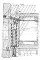
- a plummer block housing 2 is fastened on a machine frame 1, in the roller bearings 3 of which a shaft holder 4 is rotatably mounted.
- a handwheel 5 is pivotably mounted on this shaft mount 4 by means of a bolt 6.
- the shaft receptacle 4 has a square-shaped recess 4c in the exemplary embodiment, into which an end pin of a winding rod (not shown in more detail) can be inserted in a form-fitting manner. This is prevented by the surface 5b of the handwheel 5 when the shaft holder 4 is rotated from falling out and holds the winding rod or winding tree without play. It is about the above-described device as a whole around a known folding bearing with a handwheel according to German Patent 917 592.
- a toggle lever 8 is provided with two legs 10 and 10a connected to one another via a common joint 9 in the form of a bolt, the first leg 10a of which is via a bolt 7 in a recess 4b of the shaft holder 4 and its second leg 10 is also articulated via a bolt 11, but is fastened to the handwheel 5 at a point spaced from its pivot axis 6.
- This toggle lever 8 is fixed in the extended position in the illustrated closed position of the handwheel 5 and its legs 10 and 10a are, according to the dashed illustration in FIG. 1, when the handwheel 5 is opened, that is to say when the handwheel 5 is pivoted about its pivot axis 6 relative to the shaft mount 4 foldable at an angle to one another at their common joint 9.
- the handwheel 5 has a recess 5a within which the pivot bearing 11 for the second leg 10 is located, this recess 5a extended towards the rear of the handwheel in such a way that the pivoted leg 10 also has enough space.
- Fig.1 makes it clear that the toggle lever 8 engages on the one hand on the upper side of the shaft holder 4 and on the other hand above the locking opening 5b arranged in the handwheel 5 on the handwheel 5.
- the toggle lever 8 is held in place by a holding force 1 shown closed position held, which can be overcome when the toggle lever 8 bends upwards from the extended position around the common joint 9 to open the handwheel 5.
- the toggle lever 8 is secured against buckling against this opening direction by a stop 13, against which, in the exemplary embodiment, a lever arm 13a which extends from the first leg 10a engages.
- an actuating element in the form of a push rod 14 engages on the toggle lever 8, specifically on the leg 10a connected to the shaft receptacle 4 and thereby on the lever arm 13a extending therefrom, in order to fold and open the toggle lever 8 and thereby also pivot open the handwheel 5 to perform.
- 1 clearly shows that the toggle lever 8 can be moved upwards with its common joint 9 from the pivot axis 6 of the handwheel 5 when the handwheel 5 is swung open, because there is of course more space for such a kink than an opposite one Opening movement. Accordingly, the actuator 14 engages from below on the toggle lever 8 under a lever arm to the pivot bearing 7.
- the actuating member or the push rod 14 is in a hole 4a or bore in the shaft holder 4 arranged in the axial direction outside the recess 5b of the shaft holder 4 against the force of a spring 15 for releasing the toggle lever 8, i.e. for buckling slidable upwards.
- a mechanical adjusting device in the exemplary embodiment a working cylinder 16 with a piston rod 17, is provided for kinking the toggle lever 8 when the handwheel 5 is opened hen, which is screwed into a bore 2a of the bearing housing 2.
- the piston rod 17 can be moved axially and practically coaxially to the push rod 14 with the aid of the piston of the cylinder 16.
- the push rod 14 has at its lower end a collar 14a which overlaps the compression spring 15 surrounding it, the compression spring 15 being arranged together with the push rod 14 in the recess or perforation 4a.
- the compression spring 15 is supported with its end opposite the collar 4a at a constriction 4e of the bore or recess 4a. This means that the compression spring 15 is tensioned when the push rod 14 pivots the toggle lever 8 upward, and that it holds the push rod 14 and thus the toggle lever 8 in the closed position when the machine adjusting device, that is to say the working cylinder 16, does not overcome this force.
- leg 10 of the toggle lever 8 is designed as a double tab, the individual tabs of which encompass the other leg 10a in the region of the joint 9.
- the piston rod 17 can move into the bore 2a and, when the shaft holder 4 and the handwheel 5 are in the correct position, move the push rod 14 axially and thus transversely to the axis of rotation of the shaft holder 4.
- This shift takes place on the command "open” and can be done by hydraulic or pneumatic piston work, in another design of the mechanical adjustment device also by an electric motor with a crank or rack and pinion drive.
- the compression spring 15 pushes the push rod 14 following the retraction movement of the rod 17, downward and pivoted thereby over the pin 12 the toggle lever 8 until the lever arm 13a rests on the stop 13 designed as a screw and thus the toggle lever 8 is again in its extended locking position.
- the locking and opening of the handwheel and also the actual pivoting movement for the handwheel 15 can take place mechanically and remotely.
Landscapes
- Engineering & Computer Science (AREA)
- General Engineering & Computer Science (AREA)
- Mechanical Engineering (AREA)
- Transmission Devices (AREA)
- Pivots And Pivotal Connections (AREA)
Applications Claiming Priority (2)
| Application Number | Priority Date | Filing Date | Title |
|---|---|---|---|
| DE3706166 | 1987-02-26 | ||
| DE3706166A DE3706166C1 (de) | 1987-02-26 | 1987-02-26 | Klapplager |
Publications (3)
| Publication Number | Publication Date |
|---|---|
| EP0280049A2 true EP0280049A2 (fr) | 1988-08-31 |
| EP0280049A3 EP0280049A3 (en) | 1989-05-31 |
| EP0280049B1 EP0280049B1 (fr) | 1991-07-24 |
Family
ID=6321802
Family Applications (1)
| Application Number | Title | Priority Date | Filing Date |
|---|---|---|---|
| EP88101066A Expired - Lifetime EP0280049B1 (fr) | 1987-02-26 | 1988-01-26 | Palier-bascule |
Country Status (4)
| Country | Link |
|---|---|
| US (1) | US4838725A (fr) |
| EP (1) | EP0280049B1 (fr) |
| DE (2) | DE3706166C1 (fr) |
| ES (1) | ES2023955B3 (fr) |
Cited By (1)
| Publication number | Priority date | Publication date | Assignee | Title |
|---|---|---|---|---|
| EP0451698A1 (fr) * | 1990-04-12 | 1991-10-16 | BASF Aktiengesellschaft | Siège pliant pour embrayer un noyau d'enroulement expansible |
Families Citing this family (6)
| Publication number | Priority date | Publication date | Assignee | Title |
|---|---|---|---|---|
| IT1230421B (it) * | 1989-08-04 | 1991-10-21 | Cerutti Spa Off Mec | Dispositivo per il bloccaggio automatico di una bobina di materiale nastriforme. |
| DE4137921A1 (de) * | 1991-11-18 | 1993-05-19 | Windmoeller & Hoelscher | Vorrichtung zum kuppeln eines wickelwellenzapfens mit einem antriebswellenzapfen |
| ITVI940158A1 (it) * | 1994-10-28 | 1995-01-28 | Supporto di estremita' a sganciamento rapido particolarmente per assi portabobine. | |
| US5621987A (en) * | 1995-06-08 | 1997-04-22 | Rockland, Inc. | Implement coupling assembly for excavator machines and the like |
| TW526905U (en) * | 2002-07-12 | 2003-04-01 | Shi-Tsai Chen | Joint shaft device |
| DE10328273A1 (de) * | 2003-06-23 | 2005-01-27 | Von Ardenne Anlagentechnik Gmbh | Transportvorrichtung flächenförmiger Substrate, insbesondere in Vakuumbeschichtungsanlagen |
Family Cites Families (10)
| Publication number | Priority date | Publication date | Assignee | Title |
|---|---|---|---|---|
| DE917592C (de) * | 1952-08-15 | 1954-09-06 | Faerberei & Appretur Schutster | Vorrichtung zum Kuppeln von Wickelstaeben |
| US3147985A (en) * | 1961-08-28 | 1964-09-08 | Armstrong Cork Co | Driving chuck |
| US3854830A (en) * | 1973-11-12 | 1974-12-17 | Int Shoe Machine Corp | Quick-release mechanism for clamping a tool on a hub |
| DE2852510C2 (de) * | 1978-12-05 | 1983-10-27 | Kunz Maschinen- und Apparatebau GmbH, 7850 Lörrach | Vorrichtung zum Kuppeln von Wickelstäben |
| DE3026904C2 (de) * | 1980-07-16 | 1983-12-22 | Kunz Maschinen- und Apparatebau GmbH, 7850 Lörrach | Verschiebbare Lagerung für ein Wellen- bzw. Walzenlager |
| DE3127553C2 (de) * | 1981-07-11 | 1983-11-10 | Kunz Maschinen- und Apparatebau GmbH, 7850 Lörrach | Klapplager |
| DE3228739C1 (de) * | 1982-07-31 | 1984-02-02 | Kunz Maschinen- und Apparatebau GmbH, 7850 Lörrach | Vorrichtung zum Kuppeln eines Wickelstabes mit einer Mitnehmerwelle |
| DE8507454U1 (de) * | 1985-03-14 | 1985-05-23 | Ludwig Boschert GmbH & Co KG, 7850 Lörrach | Klapplager |
| DE3509108C1 (de) * | 1985-03-14 | 1986-09-04 | Ludwig Boschert GmbH & Co KG, 7850 Lörrach | Klapplager |
| DE3604611C1 (de) * | 1986-02-14 | 1987-04-16 | Kunz Maschinen Und Appbau Gmbh | Klapplager zum Kuppeln von Wickelstaeben mit einer Mitnehmerwelle |
-
1987
- 1987-02-26 DE DE3706166A patent/DE3706166C1/de not_active Expired
-
1988
- 1988-01-26 EP EP88101066A patent/EP0280049B1/fr not_active Expired - Lifetime
- 1988-01-26 DE DE8888101066T patent/DE3863790D1/de not_active Expired - Fee Related
- 1988-01-26 ES ES88101066T patent/ES2023955B3/es not_active Expired - Lifetime
- 1988-02-23 US US07/159,078 patent/US4838725A/en not_active Expired - Fee Related
Cited By (1)
| Publication number | Priority date | Publication date | Assignee | Title |
|---|---|---|---|---|
| EP0451698A1 (fr) * | 1990-04-12 | 1991-10-16 | BASF Aktiengesellschaft | Siège pliant pour embrayer un noyau d'enroulement expansible |
Also Published As
| Publication number | Publication date |
|---|---|
| EP0280049B1 (fr) | 1991-07-24 |
| DE3863790D1 (de) | 1991-08-29 |
| US4838725A (en) | 1989-06-13 |
| EP0280049A3 (en) | 1989-05-31 |
| ES2023955B3 (es) | 1992-02-16 |
| DE3706166C1 (de) | 1988-04-21 |
Similar Documents
| Publication | Publication Date | Title |
|---|---|---|
| DE3812313A1 (de) | Tuerschloss | |
| CH680522A5 (fr) | ||
| EP0156379B1 (fr) | Tiroir-caisse pour une caisse enregistreuse | |
| DE2619031C2 (fr) | ||
| EP0280049B1 (fr) | Palier-bascule | |
| DE3143636C2 (de) | Vorrichtung für längsverschiebbare Kraftfahrzeugsitze zum Koppeln der Klappbewegung der Rückenlehne mit einer Längsverschiebung des Sitzes | |
| DE3127553A1 (de) | "klapplager" | |
| DE1918746C3 (de) | Vorrichtung zum Transportieren eines Gegenstandes von einer in eine andere Lage | |
| DE699981C (de) | Pendelnd aufgehaengtes Trittbrett, insbesondere fuer Kraftfahrzeuge | |
| DE3634003A1 (de) | Vorrichtung zur betaetigung von kupplungen oder bremsen | |
| DE1554691A1 (de) | Vorrichtung zur Entnahme von Tuechern,Lappen od.dgl. aus einem Behaelter | |
| DE1259222B (de) | Betaetigungsvorrichtung zum OEffnen und Schliessen eines um eine waagerechte Achse kippbaren oder klappbaren Fluegels, insbesondere von Kipp-Schwenkfluegelfenstern, -tueren od. dgl. | |
| LU83793A1 (de) | Verriegelungsvorrichtung an koksofentueren | |
| EP0677635B1 (fr) | Serrure complémentaire de sécurité pour fenêtres ou portes | |
| AT302902B (de) | Einrichtung zur staubfreien Entleerung von Kehrichteimern | |
| DE4207656C2 (de) | Arbeitsprojektor | |
| DE7406394U (de) | Schneidvorrichtung fuer silomaterial | |
| DE1531884A1 (de) | Lastdrueckgeraet,insbesondere fuer Hubkarren | |
| DE2628898A1 (de) | Schere, insbesondere blechschere | |
| DE102004034054B3 (de) | Mantelbeschickbare Trommelwaschmaschine mit einem Laugenbehälterdeckel | |
| DE641616C (de) | Einrichtung zum Einziehen eines in der Turebene versenkbaren Tuergriffes | |
| DE4417243C2 (de) | Dosenpresse für das Zusammenpressen geleerter Dosen | |
| DE1428589C (de) | Türverschluß, insbesondere für transportable Aufbauten, z. B. von Kühlwagen | |
| DE2102612A1 (de) | Lasthebevorrichtung, insbesondere Ladekran | |
| DE1760544B2 (de) | Türverschluß für eine mit einer Rundumdichtung versehene Beschickungstür einer Wasch- oder Geschirrspülmaschine |
Legal Events
| Date | Code | Title | Description |
|---|---|---|---|
| PUAI | Public reference made under article 153(3) epc to a published international application that has entered the european phase |
Free format text: ORIGINAL CODE: 0009012 |
|
| AK | Designated contracting states |
Kind code of ref document: A2 Designated state(s): CH DE ES FR GB IT LI SE |
|
| PUAL | Search report despatched |
Free format text: ORIGINAL CODE: 0009013 |
|
| AK | Designated contracting states |
Kind code of ref document: A3 Designated state(s): CH DE ES FR GB IT LI SE |
|
| 17P | Request for examination filed |
Effective date: 19890421 |
|
| 17Q | First examination report despatched |
Effective date: 19901005 |
|
| ITF | It: translation for a ep patent filed | ||
| GRAA | (expected) grant |
Free format text: ORIGINAL CODE: 0009210 |
|
| AK | Designated contracting states |
Kind code of ref document: B1 Designated state(s): CH DE ES FR GB IT LI SE |
|
| PG25 | Lapsed in a contracting state [announced via postgrant information from national office to epo] |
Ref country code: SE Effective date: 19910724 Ref country code: GB Effective date: 19910724 |
|
| REF | Corresponds to: |
Ref document number: 3863790 Country of ref document: DE Date of ref document: 19910829 |
|
| EN | Fr: translation not filed | ||
| PG25 | Lapsed in a contracting state [announced via postgrant information from national office to epo] |
Ref country code: FR Effective date: 19911213 |
|
| PGFP | Annual fee paid to national office [announced via postgrant information from national office to epo] |
Ref country code: DE Payment date: 19911220 Year of fee payment: 5 |
|
| GBV | Gb: ep patent (uk) treated as always having been void in accordance with gb section 77(7)/1977 [no translation filed] | ||
| PGFP | Annual fee paid to national office [announced via postgrant information from national office to epo] |
Ref country code: ES Payment date: 19920130 Year of fee payment: 5 |
|
| PG25 | Lapsed in a contracting state [announced via postgrant information from national office to epo] |
Ref country code: LI Effective date: 19920131 Ref country code: CH Effective date: 19920131 |
|
| REG | Reference to a national code |
Ref country code: ES Ref legal event code: FG2A Ref document number: 2023955 Country of ref document: ES Kind code of ref document: B3 |
|
| PLBE | No opposition filed within time limit |
Free format text: ORIGINAL CODE: 0009261 |
|
| STAA | Information on the status of an ep patent application or granted ep patent |
Free format text: STATUS: NO OPPOSITION FILED WITHIN TIME LIMIT |
|
| 26N | No opposition filed | ||
| REG | Reference to a national code |
Ref country code: CH Ref legal event code: PL |
|
| REG | Reference to a national code |
Ref country code: FR Ref legal event code: ST |
|
| PG25 | Lapsed in a contracting state [announced via postgrant information from national office to epo] |
Ref country code: ES Free format text: LAPSE BECAUSE OF NON-PAYMENT OF DUE FEES Effective date: 19930127 |
|
| PG25 | Lapsed in a contracting state [announced via postgrant information from national office to epo] |
Ref country code: DE Effective date: 19931001 |
|
| REG | Reference to a national code |
Ref country code: ES Ref legal event code: FD2A Effective date: 19990405 |
|
| PG25 | Lapsed in a contracting state [announced via postgrant information from national office to epo] |
Ref country code: IT Free format text: LAPSE BECAUSE OF NON-PAYMENT OF DUE FEES;WARNING: LAPSES OF ITALIAN PATENTS WITH EFFECTIVE DATE BEFORE 2007 MAY HAVE OCCURRED AT ANY TIME BEFORE 2007. THE CORRECT EFFECTIVE DATE MAY BE DIFFERENT FROM THE ONE RECORDED. Effective date: 20050126 |