EP0280094B1 - Segment pour filtre pour l'épaississement d'une suspension de fibres - Google Patents
Segment pour filtre pour l'épaississement d'une suspension de fibres Download PDFInfo
- Publication number
- EP0280094B1 EP0280094B1 EP88101672A EP88101672A EP0280094B1 EP 0280094 B1 EP0280094 B1 EP 0280094B1 EP 88101672 A EP88101672 A EP 88101672A EP 88101672 A EP88101672 A EP 88101672A EP 0280094 B1 EP0280094 B1 EP 0280094B1
- Authority
- EP
- European Patent Office
- Prior art keywords
- screen
- segment
- sieve
- frame
- filter
- Prior art date
- Legal status (The legal status is an assumption and is not a legal conclusion. Google has not performed a legal analysis and makes no representation as to the accuracy of the status listed.)
- Expired - Lifetime
Links
- 239000000725 suspension Substances 0.000 title claims abstract description 13
- 230000008719 thickening Effects 0.000 title claims abstract description 5
- 239000000969 carrier Substances 0.000 claims abstract description 20
- 239000000835 fiber Substances 0.000 claims abstract description 19
- 239000002562 thickening agent Substances 0.000 claims abstract description 10
- 230000000284 resting effect Effects 0.000 claims abstract 2
- 238000002347 injection Methods 0.000 claims description 5
- 239000007924 injection Substances 0.000 claims description 5
- 229910000831 Steel Inorganic materials 0.000 claims 1
- 239000010959 steel Substances 0.000 claims 1
- 239000004744 fabric Substances 0.000 description 26
- 239000000463 material Substances 0.000 description 8
- 238000005266 casting Methods 0.000 description 6
- 238000004519 manufacturing process Methods 0.000 description 6
- XEEYBQQBJWHFJM-UHFFFAOYSA-N Iron Chemical compound [Fe] XEEYBQQBJWHFJM-UHFFFAOYSA-N 0.000 description 2
- 239000002657 fibrous material Substances 0.000 description 2
- 239000000706 filtrate Substances 0.000 description 2
- 239000002184 metal Substances 0.000 description 2
- 229910052751 metal Inorganic materials 0.000 description 2
- 239000007921 spray Substances 0.000 description 2
- XLYOFNOQVPJJNP-UHFFFAOYSA-N water Substances O XLYOFNOQVPJJNP-UHFFFAOYSA-N 0.000 description 2
- 229920001131 Pulp (paper) Polymers 0.000 description 1
- 230000035508 accumulation Effects 0.000 description 1
- 238000009825 accumulation Methods 0.000 description 1
- 238000004061 bleaching Methods 0.000 description 1
- 238000010276 construction Methods 0.000 description 1
- 230000000694 effects Effects 0.000 description 1
- 239000012065 filter cake Substances 0.000 description 1
- 238000001914 filtration Methods 0.000 description 1
- 230000002706 hydrostatic effect Effects 0.000 description 1
- 238000012432 intermediate storage Methods 0.000 description 1
- 229910052742 iron Inorganic materials 0.000 description 1
- 239000004745 nonwoven fabric Substances 0.000 description 1
- 239000010893 paper waste Substances 0.000 description 1
- 239000002994 raw material Substances 0.000 description 1
- 239000002002 slurry Substances 0.000 description 1
- 229910001220 stainless steel Inorganic materials 0.000 description 1
- 239000010935 stainless steel Substances 0.000 description 1
Images

Classifications
-
- D—TEXTILES; PAPER
- D21—PAPER-MAKING; PRODUCTION OF CELLULOSE
- D21F—PAPER-MAKING MACHINES; METHODS OF PRODUCING PAPER THEREON
- D21F1/00—Wet end of machines for making continuous webs of paper
- D21F1/66—Pulp catching, de-watering, or recovering; Re-use of pulp-water
-
- D—TEXTILES; PAPER
- D21—PAPER-MAKING; PRODUCTION OF CELLULOSE
- D21C—PRODUCTION OF CELLULOSE BY REMOVING NON-CELLULOSE SUBSTANCES FROM CELLULOSE-CONTAINING MATERIALS; REGENERATION OF PULPING LIQUORS; APPARATUS THEREFOR
- D21C9/00—After-treatment of cellulose pulp, e.g. of wood pulp, or cotton linters ; Treatment of dilute or dewatered pulp or process improvement taking place after obtaining the raw cellulosic material and not provided for elsewhere
- D21C9/18—De-watering; Elimination of cooking or pulp-treating liquors from the pulp
-
- D—TEXTILES; PAPER
- D21—PAPER-MAKING; PRODUCTION OF CELLULOSE
- D21D—TREATMENT OF THE MATERIALS BEFORE PASSING TO THE PAPER-MAKING MACHINE
- D21D5/00—Purification of the pulp suspension by mechanical means; Apparatus therefor
- D21D5/02—Straining or screening the pulp
- D21D5/04—Flat screens
- D21D5/046—Rotary screens
-
- Y—GENERAL TAGGING OF NEW TECHNOLOGICAL DEVELOPMENTS; GENERAL TAGGING OF CROSS-SECTIONAL TECHNOLOGIES SPANNING OVER SEVERAL SECTIONS OF THE IPC; TECHNICAL SUBJECTS COVERED BY FORMER USPC CROSS-REFERENCE ART COLLECTIONS [XRACs] AND DIGESTS
- Y10—TECHNICAL SUBJECTS COVERED BY FORMER USPC
- Y10S—TECHNICAL SUBJECTS COVERED BY FORMER USPC CROSS-REFERENCE ART COLLECTIONS [XRACs] AND DIGESTS
- Y10S264/00—Plastic and nonmetallic article shaping or treating: processes
- Y10S264/48—Processes of making filters
Definitions
- the invention relates to a sector-shaped screen segment for rotating disc filters or folded screen thickeners for thickening fiber suspensions.
- the roller is composed of several disc-shaped units, which are mounted on a common, rotatably mounted and driven support tube and each consist of several, along radii adjacent sector-shaped screen segments, which are covered with the screen fabric on the outside, the sieve carrier, which defines a cavity, defines the end faces of the filter discs.
- rake-like scrapers are arranged on the trough above the fiber suspension to be filtered, which form a kind of slide on which the detached from the filter disks Slide layers of fiber to a location outside the trough.
- the detachment of the fiber layers from the sieve is facilitated by providing a spray tube above the disc filter, with the aid of which the fiber layers are sprayed off from the sieve and thereby detached.
- the sieve segments have a type of frame with two lateral limbs running in the radial direction and one outer limb in the circumferential direction, and the sieve carriers arranged at a distance from one another in the axial direction consist of a welded wire mesh on which a plastic sieve fabric rests.
- the sieve carriers consist of perforated plates provided with holes of relatively large diameter.
- the invention is based on the object of creating a simple and inexpensive to produce sector-shaped sieve segment (in the side view the known sieve segments described have approximately the shape of a circular sector with a cut-off tip) for rotating disc filters or folded sieve thickeners for thickening fiber suspensions, in which the sieve Even if it is not designed as a perforated plate fastened to the support structure, it is subject to less wear than in the case of known sector-shaped sieve segments with a sieve movable relative to the sieve carriers.
- a known sieve segment (US Pat. No. 4,077,887) is assumed to enable simple and therefore inexpensive production, which has a frame that has a radially outer leg and one on each of its two sides, in particular in the radial direction has lateral legs, to which two sieve carriers are attached, the sieve supports arranged at a distance from one another in the axial direction and, together with one sieve lying on them, which form the two main surfaces of the sieve segment, both the sieve carrier and the frame legs being formed as castings, and according to the invention it is proposed to solve the problem, to embed the sieve in the frame legs and the sieve carriers.
- This embedding in the portafilter advantageously takes place in such a way that the material of the portafilter does not protrude beyond the outside of the sieve fabric.
- the production of the sieve segment according to the invention becomes particularly simple when the sieve carriers are cast onto the frame legs.
- each sieve segment has a frame made up of a radially outer leg and two lateral, radially extending legs and two filter holders, and a filter bag is drawn from a filter fabric over the frame and the filter holder.
- the frame legs are divided along a central plane of the sieve segment running perpendicular to the axis of rotation of the disc filter, and each half of the frame is formed together with one of the sieve carriers as a one-piece casting.
- the sieve segment halves produced in this way can then be glued, welded, screwed or simply attached to one another in some other way, screw connection being preferred because a damaged or worn sieve segment or sieve segment half can then be replaced particularly easily and quickly, as a result of which the disk filter is idle or folded screen thickener can be shortened.
- the cast parts could be metal die cast or injection molded parts.
- the sieve segments according to the invention become particularly cheap and light when the cast part is designed as a plastic injection molded part.
- any suitable material can be used for the sieve, but a fabric made of stainless steel wires or plastic threads or wires is particularly recommended.
- each sieve carrier as a grid formed by rods and to arrange the rods in particular so that they run radially and in the direction of rotation, the rods running in the direction of rotation then being opposite the rods running in the radial direction are set back in the direction of the segment interior and the sieve is only embedded in the radially extending rods, since the sieve fabric surfaces then become particularly dimensionally stable due to the small distance between the supports supporting the sieve.
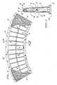
- the disc filter screen segment shown in FIGS. 1 to 3 essentially consists of two screen fabric cut parts 10 and two half shells 12, 14 designed as one-piece cast parts, each of which forms a screen support 16 and a frame half 18.
- the two frame halves together form an outer frame leg 20 in the radial direction and two lateral frame legs 22 extending in the radial direction and are firmly connected to one another along this frame leg by means of screws 24 and threaded bores 26, 12 recesses 28 being provided in the half shell for receiving the screw heads .
- the frame halves of the sieve segment according to the invention are closed and therefore also have an inner frame leg 30, whereby, as can be seen in FIG. 2, the two halves of this inner frame leg are arranged at a distance from one another in the axial direction To allow the filtrate to flow into a sieve segment carrier.
- the sieve carriers 16 consist of radial rods 32 and transverse rods 34, which are integrally connected to one another and the frame halves 18, since the entire frame halves each form a single casting, in particular a plastic injection molded part.
- the cross bars 34 are set back in relation to the radial bars 32 in the direction of the interior of the sieve segment, as can be clearly seen in FIG. 2, while the outer end faces of the radial bars 32 are aligned with the outer end faces of the frame halves 18 according to the invention. Since the cross bars 34, as can also be seen in FIG.
- Each of the sieve fabric cut parts 10 is now, according to the invention, embedded in the sieve supports formed by the outer end faces of the frame legs 20, 22, 30 and the radial rods 32 at least over part of the thickness of the sieve, but preferably over the entire sieve thickness, such as this FIG. 3 shows one of the radial rods 32 and one of the fabric sections 10 in section; this section also shows that, in the preferred embodiment of the sieve segment according to the invention, the material of the supporting structure does not protrude outward beyond the outermost elevations of the sieve or sieve fabric.
- the two frame halves can now be produced particularly easily and cheaply as plastic injection-molded parts, with a sieve fabric blank 10 being inserted into the injection mold and then the frame half being injected, the sieve fabric being embedded in the plastic forming the frame half and thus on the frame and on Filter holder is anchored.
- the screen segment shown in FIGS. 4 and 5 differs from a folded screen thickener essentially only in that the radial extension of the frame and the screen support is smaller than in the case of a disc filter screen segment, the elements of the second embodiment corresponding to the first embodiment have been given the same reference numerals as in Figures 1 to 3, but with the addition of a dash, so that a description of the details shown in Figures 4 and 5 is unnecessary.
- the bars of the two frame halves that do not support the screen fabric are arranged and dimensioned such that they abut against one another on the one hand (see FIGS. 2 and 5), which increases the stability of the screen segment, and between the edges of the screen segment facing outwards Rods and the sieve fabric still a relatively large flow cross-section remains for the filtrate.
Landscapes
- Engineering & Computer Science (AREA)
- Mechanical Engineering (AREA)
- Life Sciences & Earth Sciences (AREA)
- Wood Science & Technology (AREA)
- Combined Means For Separation Of Solids (AREA)
- Filtering Materials (AREA)
- Filtration Of Liquid (AREA)
- Paper (AREA)
- Inorganic Fibers (AREA)
- Nonwoven Fabrics (AREA)
- Oscillators With Electromechanical Resonators (AREA)
- Solid-Sorbent Or Filter-Aiding Compositions (AREA)
Claims (9)
Priority Applications (1)
| Application Number | Priority Date | Filing Date | Title |
|---|---|---|---|
| AT88101672T ATE54967T1 (de) | 1987-02-27 | 1988-02-05 | Siebsegment fuer filter zum eindicken von fasersuspensionen. |
Applications Claiming Priority (2)
| Application Number | Priority Date | Filing Date | Title |
|---|---|---|---|
| DE3706402A DE3706402C1 (de) | 1987-02-27 | 1987-02-27 | Siebsegment fuer Filter zum Eindicken von Fasersuspensionen |
| DE3706402 | 1987-02-27 |
Publications (3)
| Publication Number | Publication Date |
|---|---|
| EP0280094A2 EP0280094A2 (fr) | 1988-08-31 |
| EP0280094A3 EP0280094A3 (en) | 1989-03-01 |
| EP0280094B1 true EP0280094B1 (fr) | 1990-07-25 |
Family
ID=6321947
Family Applications (1)
| Application Number | Title | Priority Date | Filing Date |
|---|---|---|---|
| EP88101672A Expired - Lifetime EP0280094B1 (fr) | 1987-02-27 | 1988-02-05 | Segment pour filtre pour l'épaississement d'une suspension de fibres |
Country Status (7)
| Country | Link |
|---|---|
| US (1) | US4950403A (fr) |
| EP (1) | EP0280094B1 (fr) |
| JP (1) | JP2645057B2 (fr) |
| AT (1) | ATE54967T1 (fr) |
| CA (1) | CA1324344C (fr) |
| DE (2) | DE3706402C1 (fr) |
| FI (1) | FI85341C (fr) |
Families Citing this family (38)
| Publication number | Priority date | Publication date | Assignee | Title |
|---|---|---|---|---|
| US5254250A (en) * | 1991-05-30 | 1993-10-19 | Membrex, Inc. | Rotary filtration device and filter pack therefor |
| US5679249A (en) * | 1991-12-24 | 1997-10-21 | Pall Corporation | Dynamic filter system |
| AT401069B (de) * | 1993-06-23 | 1996-06-25 | Leripa Kunststoff Gmbh & Co Kg | Randabdichtung für entwässerungselemente |
| US6117322A (en) * | 1993-06-23 | 2000-09-12 | Pall Corporation | Dynamic filter system |
| AT403064B (de) * | 1995-09-15 | 1997-11-25 | Andritz Patentverwaltung | Scheibenfilter zum abtrennen von flüssigkeiten aus einer suspension, insbesondere faserstoffsuspension |
| US5707517A (en) * | 1995-11-27 | 1998-01-13 | Membrex, Inc. | Immersible rotary disc filtration device |
| RU2165803C2 (ru) | 1996-08-20 | 2001-04-27 | Бюлер Аг | Плоское сито |
| US5766472A (en) * | 1996-10-29 | 1998-06-16 | Illinois Tool Works Inc. | Method and apparatus for a filter assembly |
| DE19706601C1 (de) * | 1997-02-20 | 1998-11-12 | Buehler Ag | Siebrahmen für Plansichter und Verfahren zu dessen Herstellung |
| DE69827046T2 (de) * | 1997-03-01 | 2005-03-03 | United Wire Ltd. | Einrichtung zum Reparieren oder Aufbereiten eines Filtersiebes |
| US5993674A (en) * | 1998-02-24 | 1999-11-30 | Membrex, Inc. | Rotary disc filtration device with means to reduce axial forces |
| DE29815098U1 (de) | 1998-08-22 | 1998-11-05 | Schwarzkopf, Josef, 94508 Schöllnach | Filtereinrichtung |
| US6305549B1 (en) * | 1999-07-06 | 2001-10-23 | Southwestern Wire Cloth, Inc. | Vibrating screen assembly of dissimilar materials |
| US20010050250A1 (en) | 1999-09-14 | 2001-12-13 | Olli Hognabba | Corrosion-resistant filter element |
| SE526692E (sv) | 2003-02-27 | 2013-07-16 | Veolia Water Solutions & Tech | Modul för uppbyggnad av skivfilter |
| AT412259B (de) * | 2003-06-04 | 2004-12-27 | Andritz Ag Maschf | Verfahren zum herstellen eines sektorförmigen filterelements und filterelement |
| US20050027006A1 (en) | 2003-07-28 | 2005-02-03 | Reuben Matalon | Methods and materials for treating conditions associated with metabolic disorders |
| WO2007061447A2 (fr) * | 2005-11-15 | 2007-05-31 | Sefar Filtration Inc. | Cadre de tamis jetable prealablement tendu et procede de fabrication correspondant |
| EP1872843A1 (fr) * | 2006-06-26 | 2008-01-02 | Hydrotech Veolia Water Systems Aktiebolag | Cadre pour un filtre à disques |
| EP2051791B1 (fr) | 2006-08-14 | 2014-10-08 | Evoqua Water Technologies LLC | Filtre en forme de disque à débit élevé |
| US8118175B2 (en) | 2007-07-18 | 2012-02-21 | Siemens Industry, Inc. | Venting device for a disc filter |
| US8801929B2 (en) * | 2007-07-18 | 2014-08-12 | Evoqua Water Technologies Llc | Trash tolerant filter support for a disc filter |
| US8894856B2 (en) * | 2008-03-28 | 2014-11-25 | Evoqua Water Technologies Llc | Hybrid aerobic and anaerobic wastewater and sludge treatment systems and methods |
| KR20100136989A (ko) * | 2008-03-28 | 2010-12-29 | 지멘스 워터 테크놀로지스 코포레이션 | 호기성 및 혐기성 하이브리드 폐수 및 슬러지 처리 시스템 및 방법 |
| US9359236B2 (en) | 2010-08-18 | 2016-06-07 | Evoqua Water Technologies Llc | Enhanced biosorption of wastewater organics using dissolved air flotation with solids recycle |
| SE535159C2 (sv) * | 2010-09-02 | 2012-05-02 | Veolia Water Solutions & Tech | Förfarande för att tillverka ett filtersegment till ett skivfilter samt filtersegmentet |
| CN102614703A (zh) * | 2011-01-31 | 2012-08-01 | 江苏博思达环保科技有限公司 | 转盘过滤器用盘片 |
| WO2013032958A1 (fr) * | 2011-08-29 | 2013-03-07 | Karl Gabrielsson | Segment filtrant à structure légère |
| DE102012222400B4 (de) | 2012-12-06 | 2025-06-26 | BSH Hausgeräte GmbH | Scheibenfilterplatte mit Trägerelement |
| AU2014262972B2 (en) | 2013-05-06 | 2017-09-28 | Evoqua Water Technologies Llc | Wastewater biosorption with dissolved air flotation |
| CN114405122B (zh) | 2014-06-05 | 2024-05-24 | 懿华水处理技术有限责任公司 | 过滤板以及制作过滤板的方法 |
| JP6618554B2 (ja) * | 2015-07-03 | 2019-12-11 | ガウドフリン | 漸進的厚みを有するセクター |
| ES2927357T3 (es) | 2016-08-12 | 2022-11-04 | Evoqua Water Tech Llc | Filtro de disco de medios dobles prepantallla de filtro de disco |
| US11255046B2 (en) * | 2016-10-17 | 2022-02-22 | Andritz Oy | Screen assembly for pulp digesters and other treatment vessels in pulp production |
| SE540721C2 (en) | 2017-06-02 | 2018-10-23 | Nordic Water Prod Ab | Filter element for use in a filter disc |
| CN107227649A (zh) * | 2017-06-13 | 2017-10-03 | 太仓市宇航造纸机械厂 | 一种造纸用双层过滤网 |
| US11000791B2 (en) * | 2019-03-06 | 2021-05-11 | Veolia Water Solutions & Technologies Support | Rotary disc filter having backwash guides |
| US12220657B2 (en) * | 2021-04-30 | 2025-02-11 | Pall Corporation | Filter disk segments |
Citations (2)
| Publication number | Priority date | Publication date | Assignee | Title |
|---|---|---|---|---|
| US1767078A (en) * | 1927-11-29 | 1930-06-24 | Johnson John | Screen for filter presses |
| US4077887A (en) * | 1977-05-17 | 1978-03-07 | Sigmund Coll Langvik | Filter disc for vacuum filter system |
Family Cites Families (12)
| Publication number | Priority date | Publication date | Assignee | Title |
|---|---|---|---|---|
| US1685085A (en) * | 1924-02-01 | 1928-09-25 | United Filters Corp | Dewatering apparatus |
| US1746409A (en) * | 1926-12-06 | 1930-02-11 | Oliver United Filters Inc | Filter leaf |
| US2444147A (en) * | 1945-03-15 | 1948-06-29 | Air Maze Corp | Liquid filter element |
| US2682205A (en) * | 1949-06-28 | 1954-06-29 | Bertram J Vincent | Screen plate for papermaking machines |
| US2964194A (en) * | 1957-04-17 | 1960-12-13 | Dorr Oliver Inc | Filter construction |
| US3610419A (en) * | 1969-06-09 | 1971-10-05 | Improved Machinery Inc | Filter leaf |
| US3679061A (en) * | 1970-06-15 | 1972-07-25 | Envirotech Corp | Molded filter leaf |
| US3917534A (en) * | 1974-04-17 | 1975-11-04 | Plastic Tech Inc | Filter sector |
| FR2375893A1 (fr) * | 1976-12-31 | 1978-07-28 | Eurogest | Boitier pour filtre a air, et filtre a air equipe d'un tel boitier |
| US4330405A (en) * | 1980-09-29 | 1982-05-18 | Davis Kent L | Vacuum disc filter |
| NL8400662A (nl) * | 1984-03-01 | 1985-10-01 | Amafilter Bv | Schijfvormig filterelement. |
| SE453158B (sv) * | 1985-02-20 | 1988-01-18 | Bjarne Nilsson | Skivfilterelement for ett roterbart skivfilter |
-
1987
- 1987-02-27 DE DE3706402A patent/DE3706402C1/de not_active Expired
-
1988
- 1988-02-05 DE DE8888101672T patent/DE3860346D1/de not_active Expired - Fee Related
- 1988-02-05 EP EP88101672A patent/EP0280094B1/fr not_active Expired - Lifetime
- 1988-02-05 AT AT88101672T patent/ATE54967T1/de not_active IP Right Cessation
- 1988-02-10 US US07/154,634 patent/US4950403A/en not_active Expired - Lifetime
- 1988-02-12 CA CA000558817A patent/CA1324344C/fr not_active Expired - Fee Related
- 1988-02-12 FI FI880649A patent/FI85341C/fi not_active IP Right Cessation
- 1988-02-26 JP JP63042395A patent/JP2645057B2/ja not_active Expired - Fee Related
Patent Citations (2)
| Publication number | Priority date | Publication date | Assignee | Title |
|---|---|---|---|---|
| US1767078A (en) * | 1927-11-29 | 1930-06-24 | Johnson John | Screen for filter presses |
| US4077887A (en) * | 1977-05-17 | 1978-03-07 | Sigmund Coll Langvik | Filter disc for vacuum filter system |
Also Published As
| Publication number | Publication date |
|---|---|
| EP0280094A2 (fr) | 1988-08-31 |
| JPS63219691A (ja) | 1988-09-13 |
| DE3706402C1 (de) | 1988-07-07 |
| FI85341C (fi) | 1992-04-10 |
| FI880649L (fi) | 1988-08-28 |
| JP2645057B2 (ja) | 1997-08-25 |
| FI85341B (fi) | 1991-12-31 |
| EP0280094A3 (en) | 1989-03-01 |
| US4950403A (en) | 1990-08-21 |
| DE3860346D1 (de) | 1990-08-30 |
| ATE54967T1 (de) | 1990-08-15 |
| CA1324344C (fr) | 1993-11-16 |
| FI880649A0 (fi) | 1988-02-12 |
Similar Documents
| Publication | Publication Date | Title |
|---|---|---|
| DE3706402C1 (de) | Siebsegment fuer Filter zum Eindicken von Fasersuspensionen | |
| DE69835963T2 (de) | Drehscheibenfilter | |
| DE602004003562T3 (de) | Drehscheibenfilter und modul zur herstellung desselben | |
| DE2501547B2 (de) | Zylindersieb zur Trennung von flüssigen Bestandteilen von festen Bestandteilen | |
| DE2629848A1 (de) | Verfahren zum filtern von trueben fluessigkeiten und vorrichtung zur durchfuehrung des verfahrens | |
| CH678954A5 (fr) | ||
| DE102004055195A1 (de) | Scheibenfilter mit Sektoren | |
| DE69414563T2 (de) | Scheibenfiltersektor | |
| DE2826734A1 (de) | Filtersektor | |
| DE2547017A1 (de) | Zerfaserungsvorrichtung fuer papierstoff | |
| DE3113624A1 (de) | "rueckspuelbare filtriervorrichtung" | |
| DE3528429A1 (de) | Scheibeneindicker | |
| DE2902432C2 (de) | Eindickfilter | |
| DE9218957U1 (de) | Filtervorrichtung | |
| DE2234076B2 (de) | Rührwerksmühle | |
| DE3043011A1 (de) | Vorrichtung zum extrahieren von fluessigkeit aus sich bewegenden suspensionen | |
| DE102020117493A1 (de) | Rotationsscheibenfilter | |
| DE3876515T2 (de) | Sektor fuer scheibendrehfilter. | |
| DE3342689C2 (de) | Filtervorrichtung zum Entfernen von Verunreinigungen aus Flüssigkeiten, insbesondere aus Dispersionsfarben | |
| DE602004006611T2 (de) | Stabsiebkorb zur Filtrierung von Fasersuspensionen und Verfahren zu dessen Herstellung | |
| DE2750499A1 (de) | Sortierer fuer fasersuspensionen | |
| EP2780158B1 (fr) | Presse à vis ii | |
| DE964322C (de) | Verfahren und Vorrichtung zum Filtern von Fluessigkeiten | |
| DE3875592T2 (de) | Rotierender filter mit aeusseren filtratleitungen. | |
| DE69109669T2 (de) | Scheibenfilter. |
Legal Events
| Date | Code | Title | Description |
|---|---|---|---|
| PUAI | Public reference made under article 153(3) epc to a published international application that has entered the european phase |
Free format text: ORIGINAL CODE: 0009012 |
|
| AK | Designated contracting states |
Kind code of ref document: A2 Designated state(s): AT DE FR GB IT SE |
|
| PUAL | Search report despatched |
Free format text: ORIGINAL CODE: 0009013 |
|
| AK | Designated contracting states |
Kind code of ref document: A3 Designated state(s): AT DE FR GB IT SE |
|
| 17P | Request for examination filed |
Effective date: 19890321 |
|
| 17Q | First examination report despatched |
Effective date: 19890803 |
|
| GRAA | (expected) grant |
Free format text: ORIGINAL CODE: 0009210 |
|
| AK | Designated contracting states |
Kind code of ref document: B1 Designated state(s): AT DE FR GB IT SE |
|
| REF | Corresponds to: |
Ref document number: 54967 Country of ref document: AT Date of ref document: 19900815 Kind code of ref document: T |
|
| ITF | It: translation for a ep patent filed | ||
| REF | Corresponds to: |
Ref document number: 3860346 Country of ref document: DE Date of ref document: 19900830 |
|
| ET | Fr: translation filed | ||
| GBT | Gb: translation of ep patent filed (gb section 77(6)(a)/1977) | ||
| REG | Reference to a national code |
Ref country code: GB Ref legal event code: 727 |
|
| REG | Reference to a national code |
Ref country code: GB Ref legal event code: 727 |
|
| PLBE | No opposition filed within time limit |
Free format text: ORIGINAL CODE: 0009261 |
|
| STAA | Information on the status of an ep patent application or granted ep patent |
Free format text: STATUS: NO OPPOSITION FILED WITHIN TIME LIMIT |
|
| REG | Reference to a national code |
Ref country code: GB Ref legal event code: 727B |
|
| 26N | No opposition filed | ||
| REG | Reference to a national code |
Ref country code: GB Ref legal event code: SP |
|
| ITTA | It: last paid annual fee | ||
| EAL | Se: european patent in force in sweden |
Ref document number: 88101672.9 |
|
| REG | Reference to a national code |
Ref country code: GB Ref legal event code: IF02 |
|
| PGFP | Annual fee paid to national office [announced via postgrant information from national office to epo] |
Ref country code: GB Payment date: 20050202 Year of fee payment: 18 |
|
| PGFP | Annual fee paid to national office [announced via postgrant information from national office to epo] |
Ref country code: AT Payment date: 20050207 Year of fee payment: 18 |
|
| PGFP | Annual fee paid to national office [announced via postgrant information from national office to epo] |
Ref country code: FR Payment date: 20050211 Year of fee payment: 18 |
|
| PGFP | Annual fee paid to national office [announced via postgrant information from national office to epo] |
Ref country code: SE Payment date: 20050215 Year of fee payment: 18 |
|
| PGFP | Annual fee paid to national office [announced via postgrant information from national office to epo] |
Ref country code: DE Payment date: 20050324 Year of fee payment: 18 |
|
| PG25 | Lapsed in a contracting state [announced via postgrant information from national office to epo] |
Ref country code: GB Free format text: LAPSE BECAUSE OF NON-PAYMENT OF DUE FEES Effective date: 20060205 Ref country code: AT Free format text: LAPSE BECAUSE OF NON-PAYMENT OF DUE FEES Effective date: 20060205 |
|
| PG25 | Lapsed in a contracting state [announced via postgrant information from national office to epo] |
Ref country code: SE Free format text: LAPSE BECAUSE OF NON-PAYMENT OF DUE FEES Effective date: 20060206 |
|
| PGFP | Annual fee paid to national office [announced via postgrant information from national office to epo] |
Ref country code: IT Payment date: 20060228 Year of fee payment: 19 |
|
| PG25 | Lapsed in a contracting state [announced via postgrant information from national office to epo] |
Ref country code: DE Free format text: LAPSE BECAUSE OF NON-PAYMENT OF DUE FEES Effective date: 20060901 |
|
| EUG | Se: european patent has lapsed | ||
| GBPC | Gb: european patent ceased through non-payment of renewal fee |
Effective date: 20060205 |
|
| REG | Reference to a national code |
Ref country code: FR Ref legal event code: ST Effective date: 20061031 |
|
| PG25 | Lapsed in a contracting state [announced via postgrant information from national office to epo] |
Ref country code: FR Free format text: LAPSE BECAUSE OF NON-PAYMENT OF DUE FEES Effective date: 20060228 |
|
| PG25 | Lapsed in a contracting state [announced via postgrant information from national office to epo] |
Ref country code: IT Free format text: LAPSE BECAUSE OF NON-PAYMENT OF DUE FEES Effective date: 20070205 |