EP0280105A1 - Anti-Larsen-Anordnung für Fernsprechapparat - Google Patents
Anti-Larsen-Anordnung für Fernsprechapparat Download PDFInfo
- Publication number
- EP0280105A1 EP0280105A1 EP88101780A EP88101780A EP0280105A1 EP 0280105 A1 EP0280105 A1 EP 0280105A1 EP 88101780 A EP88101780 A EP 88101780A EP 88101780 A EP88101780 A EP 88101780A EP 0280105 A1 EP0280105 A1 EP 0280105A1
- Authority
- EP
- European Patent Office
- Prior art keywords
- level
- threshold
- microphone
- controlled attenuator
- loudspeaker
- Prior art date
- Legal status (The legal status is an assumption and is not a legal conclusion. Google has not performed a legal analysis and makes no representation as to the accuracy of the status listed.)
- Granted
Links
- 230000010355 oscillation Effects 0.000 claims abstract description 9
- 230000005284 excitation Effects 0.000 claims description 22
- 230000004913 activation Effects 0.000 claims description 10
- 230000004044 response Effects 0.000 claims description 7
- 230000003313 weakening effect Effects 0.000 claims description 5
- 230000005540 biological transmission Effects 0.000 claims description 3
- 238000005259 measurement Methods 0.000 claims description 3
- 230000007423 decrease Effects 0.000 claims description 2
- 230000003213 activating effect Effects 0.000 claims 1
- 238000000926 separation method Methods 0.000 claims 1
- 230000000694 effects Effects 0.000 abstract description 16
- OKTJSMMVPCPJKN-UHFFFAOYSA-N Carbon Chemical compound [C] OKTJSMMVPCPJKN-UHFFFAOYSA-N 0.000 description 9
- 229910052799 carbon Inorganic materials 0.000 description 9
- 238000010586 diagram Methods 0.000 description 4
- 230000000977 initiatory effect Effects 0.000 description 4
- 230000005520 electrodynamics Effects 0.000 description 3
- 238000001514 detection method Methods 0.000 description 2
- 230000009471 action Effects 0.000 description 1
- 230000001154 acute effect Effects 0.000 description 1
- 230000002411 adverse Effects 0.000 description 1
- 239000002775 capsule Substances 0.000 description 1
- 230000008878 coupling Effects 0.000 description 1
- 238000010168 coupling process Methods 0.000 description 1
- 238000005859 coupling reaction Methods 0.000 description 1
- 230000001627 detrimental effect Effects 0.000 description 1
- 230000002349 favourable effect Effects 0.000 description 1
- 238000009499 grossing Methods 0.000 description 1
- 238000004519 manufacturing process Methods 0.000 description 1
- 238000000034 method Methods 0.000 description 1
- 238000012856 packing Methods 0.000 description 1
- 230000035945 sensitivity Effects 0.000 description 1
Images

Classifications
-
- H—ELECTRICITY
- H04—ELECTRIC COMMUNICATION TECHNIQUE
- H04M—TELEPHONIC COMMUNICATION
- H04M9/00—Arrangements for interconnection not involving centralised switching
- H04M9/08—Two-way loud-speaking telephone systems with means for conditioning the signal, e.g. for suppressing echoes for one or both directions of traffic
- H04M9/10—Two-way loud-speaking telephone systems with means for conditioning the signal, e.g. for suppressing echoes for one or both directions of traffic with switching of direction of transmission by voice frequency
Definitions
- the present invention relates to a Larsen anti-effect device installed in a loudspeaker telephone set.
- French patent 2,500,698 discloses a Larsen anti-effect device which comprises a controlled attenuator placed at the input of the amplifier of the loudspeaker of the telephone set and put into service in the presence of oscillations at the frequency of approximately 2 kHz, in the output signal from the microphone of the telephone set which are characteristic of a Larsen effect.
- This anti-Larsen effect device replaces the unpleasant whistling of a Larsen effect with low amplitude sound "BIPS" until the subscriber moves his microphone away from the speaker enough to stop the Larsen effect.
- the microphone is often close enough to the loudspeaker for the Larsen effect to start and cause the emission of audible "BEEPS” detrimental to the comfort of use. the maid.
- the present invention aims to combat the aforementioned drawback.
- It also aims to improve the subjective listening comfort of a subscriber in the case of telephone sets employing a microphone with linear electrical efficiency such as an electrodynamic microphone or a microphone with electrets which are in a noisy environment of a subjective listening comfort less than those using the traditional carbon microphone.
- a Larsen anti-effect device comprising, in addition to the controlled attenuator placed in front of the amplifier of the loudspeaker and activated in the presence of oscillations at the frequency of approximately 2 kHz in the microphone signal, an attenuator controlled interposed between the microphone of the telephone set and its two-wire-four-wire switching circuit and put into service each time the microphone is subjected to an acoustic excitation pressure below a minimum threshold proportional to the level of the signal speaker excitement.
- the device anti-effect Larsen also comprises an additional controlled attenuator which is inserted in front of the amplifier of the loudspeaker and which functions in opposition with the controlled attenuator inserted behind the microphone.
- the controlled attenuator inserted behind the microphone is controlled by a variable threshold level detector which is connected to the microphone output and which has a first response time of the order of 10 ms for generate a command to activate the attenuator and a second response time of the order of 3 ms to generate a command to deactivate the attenuator.
- FIG. 1 is an electrical diagram of a Larsen anti-effect device according to the invention mounted in a loudspeaker telephone or terminal and
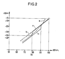
- FIG. 2 a diagram of curves illustrating the characteristics of this device.
- FIG. 1 There are in FIG. 1 the main elements of a loudspeaker telephone set connected to a two-wire telephone line 4, in particular, the two-wire-four-wire switching circuit 3 locally separating the transmit LE and receive LS directions which are superimposed in the two-wire telephone line 4, the microphone 1 connected to the transmission channel LE, on the four-wire side, of the routing circuit 3 as well as the earpiece 6 and the speaker 8 with its amplifier 7 connected to the reception channel LS , on the four-wire side, of the routing circuit 3.
- a Larsen anti-effect device with its controlled attenuator 13 which is inserted in front of the input of amplifier 7 of speaker 8 and whose activation command 15 is controlled by a detector 9 of oscillations at a frequency of around 2 kHz operating on the microphone output 1.
- the microphone 1 is a linear electric efficiency microphone with amplified output such as an electro-dynamic microphone or a microphone with electrets equipped with an amplifier, because this type of microphone has, since the advent of the technique of integrated circuits, characteristics clearly more efficient than carbon microphones in particular from the point of view of congestion, current consumption, fidelity of voice reproduction and cost of mass production.
- the controlled attenuator 13, represented by a resistive divider bridge, one of the resistors of which is shunted by a controllable contact, is in fact produced in an integrable form for example according to the embodiment described in French patent 2,500,698 relating to his figure 2.
- the oscillation detector 9 is formed by means of a high-pass filter with serial capacity and parallel resistance isolating the oscillations at 2 kHz from the Larsen effect and the high frequencies of speech followed by a rectifier detecting the envelope of the signal delivered by the high-pass filter, a low-pass smoothing filter with series resistance and parallel capacity attenuating the high frequencies of speech and a threshold comparator.
- the controlled attenuator 14 In the event of detection of significant oscillations around 2 kHz, in the amplified signal output from the microphone 1, it activates the controlled attenuator 14, that is to say causes the signal at the input of the amplifier 7 of the speaker 8, in order to stop the looping at the origin of the Larsen effect while in the absence of detection of these oscillations, it deactivates the controlled attenuator 13 so that the - this allows the excitation signal of amplifier 7 to pass through it speaker 8 without weakening it.
- the Larsen anti-effect device limited to these already known elements eliminates the unpleasant hiss generated by a Larsen effect and replaces it with low amplitude sound "BIPS" which signal to the subscriber that his microphone is too close to the loudspeaker and that it must be kept away.
- the Larsen effect occurs each time the handset is lifted and hung up on its base and results in the emission of audible BIPS which adversely affects the comfort of using the telephone set.
- a second controlled attenuator 80 which is interposed between the amplified output of the microphone 1 and the transmission channel LE, on the four-wire side of the switching circuit 3 and whose activation command 82 is controlled by a level detector 83 with variable threshold operating on the amplified output of the microphone 1.
- This second controlled attenuator 80 is represented like the first 13 by a resistive divider bridge, one of the resistors of which is shunted by a controllable contact and is, like this controlled attenuator, produced using active elements in an integrable form. It is put into service and weakens the signal level of the microphone 1 arriving at a switching circuit 3 by around 7 dB when its activation command 82 receives a positive voltage close to the bias voltage. It is put out of service and is let through by the signal from the microphone 1 without attenuating it when its activation command 82 receives a very low zero voltage.
- the variable threshold level detector 83 has a level measurement input 830 connected to the amplified output of the microphone 1 and a threshold adjustment input 831 connected to the output of a level threshold generator 84 operating on the basis of the signal. output of amplifier 7 of speaker 8. It includes, at its level measurement input 830, a rectifier 832 followed by a low-pass filter with series resistance 833, parallel capacity 834 and parallel discharge resistance 835 capacity and a comparator 835 which is connected by its inverting input at the output of the low-pass filter and by its non-inverting input, at the threshold adjustment input 831, and which controls the activation command 82 of the controlled attenuator 80.
- the rectifier 832 detects the signal envelope of the amplified output of microphone 1.
- the low-pass filter integrates this envelope with a rise time constant of the order of 3 ms determined by the values of the series resistance 833 and of the parallel capacitance 834, and with a fall time constant of the order of 10 ms determined by the values of the parallel capacitance 834 and the parallel resistance 835.
- the level detector with variable threshold 83 a first response time of 10 ms to activate the second controlled attenuator 80, when the signal level of the amplified output of the microphone 1 decreases, which avoids chopping the speech of the near subscriber, and a second time response of 3 ms to deactivate the second controlled attenuator 80 during an increase in level of the signal of the amplified output of the microphone 1 which avoids taking into account impulse noise.
- the comparator 836 receives on its non-inverting input a voltage generated by the level threshold generator 84. This varies proportionally to the level of excitation of the loudspeaker in a range of -15 to -30 dBm which corresponds for the microphone 1 at an acoustic excitation pressure contained in a range starting from 7- to 80 dBSPL in the absence of excitation of the speaker 8 and ending at 80 dBSPL at the maximum of the excitation of the speaker 8.
- the comparator 836 When the applied voltage at its inverting input is lower than the threshold voltage applied to its non-inverting input, which occurs during a silence by the near subscriber, the comparator 836 delivers a positive voltage at output, close to the bias voltage which activates the controlled attenuator 80 and causes the signal from the microphone 1 reaching the switching circuit 3 to be weakened. When the voltage applied to its inverting input is greater than the threshold voltage applied to its input non inverting what which occurs when the near subscriber speaks, the comparator 836 delivers at output a zero or very low voltage which deactivates the controlled attenuator 80 which can be passed over by the signal from the microphone 1 without weakening it.
- the level threshold generator 84 comprises as input a high-pass filter with series capacity 840 and parallel resistance 841 followed by a rectifier 842, a low-pass filter with series resistance 843, parallel capacity 844 and parallel resistance 845 of discharge of the capacitance, and of a differential amplifier 846 which is connected by its inverting input to an adjustable bias bridge 847 and by its non-inverting input at the output of the low-pass filter, and which controls the threshold adjustment input 831 of the variable threshold level detector 83.
- the input high pass filter 840, 841 of the level threshold generator 84 eliminates from the input signal the low frequency components to which the speaker 8 is not very sensitive.
- the rectifier 842 detects the envelope of the excitation signal from the speaker 8 deprived of its components at the lowest frequencies.
- the low-pass filter stores the peak value of this envelope. It has a rise time of the order of 1 ms determined by the values of the series resistance 843 and the parallel capacity 844 and a fall time of the order of 100 ms determined by the values of the parallel capacity 844 of the resistance parallel 845.
- the differential amplifier 846 generates from this peak value a voltage constituting the level threshold for the variable threshold level detector 83, a voltage which can be brought in the range from -15 to -30 dBm, by adjustment of the adjustable bias bridge 847.
- the second controlled attenuator 80 and put into service during silences of the near subscriber where it improves the efficiency of the anti-Larsen device and reduces the ambient noise of the earpiece 6, by introducing a weakening of 7 dB on the signal paths of the microphone 1 through the leaks of the routing circuit 3 both to the loudspeaker 8 and to the earpiece 6.
- This implementation during the silence of the close subscriber takes account of the influence of the loudspeaker 8 on the level of the ambient noise. It takes place at a lower level when the excitation signal from speaker 8 is weak because the risk of initiation of a Larsen effect only occurs when the microphone 1 and speaker 8 are brought together during the handset off-hook and on-hook operations when this commissioning has already taken place.
- the excitation signal from the speaker 8 is medium or strong, the activation of the second attenuator 80 takes place for a higher level of ambient noise proportional to the acoustic signal from speaker 8 at the origin of the risks of initiating a Larsen effect.
- a third controlled attenuator 85 identical to the second controlled attenuator 80 is interposed with the first controlled attenuator 13 at the input of the amplifier 7 of the loudspeaker 8 and controlled in opposition to the second controlled attenuator 80 by means of an inverting amplifier 86 connected at the output of the variable threshold level detector 83.
- FIG. 2 illustrate in a the average variation of the voltage delivered by a carbon microphone as a function of the acoustic excitation pressure when it is crossed by a bias current of 30 mA.
- This voltage variation represented by a dashed curve is only an average because the carbon microphones have a fluctuating response curve, in close dependence on the distribution and the packing of the grains of carbon in their capsule which are a function of the conditions prior to use.
- the second attenuator 80 is put into service and weakens the signal from the microphone arriving at the switch circuit by 7 dB so that the level of the signal emitted online and especially that of the leaks towards the earpiece and the loudspeaker becomes lower than that of the signal generated by a carbon microphone during the silences of the close subscriber, than 'the far subscriber speak or not, which improves the subjective listening comfort and reduces the risk of initiating Larsen effect.
Landscapes
- Engineering & Computer Science (AREA)
- Signal Processing (AREA)
- Telephone Set Structure (AREA)
- Circuit For Audible Band Transducer (AREA)
- Telephonic Communication Services (AREA)
- Percussion Or Vibration Massage (AREA)
- Telephone Function (AREA)
- Fittings On The Vehicle Exterior For Carrying Loads, And Devices For Holding Or Mounting Articles (AREA)
- Electrophonic Musical Instruments (AREA)
- Control Of Amplification And Gain Control (AREA)
Priority Applications (1)
| Application Number | Priority Date | Filing Date | Title |
|---|---|---|---|
| AT88101780T ATE63659T1 (de) | 1987-02-10 | 1988-02-08 | Anti-larsen-anordnung fuer fernsprechapparat. |
Applications Claiming Priority (2)
| Application Number | Priority Date | Filing Date | Title |
|---|---|---|---|
| FR878701650A FR2610772B2 (fr) | 1987-02-10 | 1987-02-10 | Dispositif anti-effet larsen pour poste telephonique |
| FR8701650 | 1987-02-10 |
Publications (2)
| Publication Number | Publication Date |
|---|---|
| EP0280105A1 true EP0280105A1 (de) | 1988-08-31 |
| EP0280105B1 EP0280105B1 (de) | 1991-05-15 |
Family
ID=9347770
Family Applications (1)
| Application Number | Title | Priority Date | Filing Date |
|---|---|---|---|
| EP88101780A Expired - Lifetime EP0280105B1 (de) | 1987-02-10 | 1988-02-08 | Anti-Larsen-Anordnung für Fernsprechapparat |
Country Status (6)
| Country | Link |
|---|---|
| EP (1) | EP0280105B1 (de) |
| AT (1) | ATE63659T1 (de) |
| DE (1) | DE3862772D1 (de) |
| ES (1) | ES2022480B3 (de) |
| FR (1) | FR2610772B2 (de) |
| GR (1) | GR3002352T3 (de) |
Citations (3)
| Publication number | Priority date | Publication date | Assignee | Title |
|---|---|---|---|---|
| FR2164357A5 (de) * | 1971-12-08 | 1973-07-27 | Philips Nv | |
| FR2500698A1 (fr) * | 1981-02-20 | 1982-08-27 | Thomson Csf Mat Tel | Dispositif anti-effet larsen pour poste telephonique |
| EP0082755A1 (de) * | 1981-12-18 | 1983-06-29 | Thomson-Csf Telephone | Telefonapparat mit Sprachverstärkern |
-
1987
- 1987-02-10 FR FR878701650A patent/FR2610772B2/fr not_active Expired
-
1988
- 1988-02-08 DE DE8888101780T patent/DE3862772D1/de not_active Expired - Lifetime
- 1988-02-08 ES ES88101780T patent/ES2022480B3/es not_active Expired - Lifetime
- 1988-02-08 EP EP88101780A patent/EP0280105B1/de not_active Expired - Lifetime
- 1988-02-08 AT AT88101780T patent/ATE63659T1/de not_active IP Right Cessation
-
1991
- 1991-07-24 GR GR91401068T patent/GR3002352T3/el unknown
Patent Citations (3)
| Publication number | Priority date | Publication date | Assignee | Title |
|---|---|---|---|---|
| FR2164357A5 (de) * | 1971-12-08 | 1973-07-27 | Philips Nv | |
| FR2500698A1 (fr) * | 1981-02-20 | 1982-08-27 | Thomson Csf Mat Tel | Dispositif anti-effet larsen pour poste telephonique |
| EP0082755A1 (de) * | 1981-12-18 | 1983-06-29 | Thomson-Csf Telephone | Telefonapparat mit Sprachverstärkern |
Also Published As
| Publication number | Publication date |
|---|---|
| FR2610772B2 (fr) | 1989-04-28 |
| FR2610772A2 (fr) | 1988-08-12 |
| EP0280105B1 (de) | 1991-05-15 |
| ATE63659T1 (de) | 1991-06-15 |
| GR3002352T3 (en) | 1992-12-30 |
| ES2022480B3 (es) | 1991-12-01 |
| DE3862772D1 (de) | 1991-06-20 |
Similar Documents
| Publication | Publication Date | Title |
|---|---|---|
| US4543665A (en) | Speakerphone with wireless infrared microphone | |
| FR2502370A1 (fr) | Dispositif de reduction du bruit dans un signal de parole mele de bruit | |
| FR2719173A1 (fr) | Appareil de communication à réglage du bruit. | |
| EP0812504A1 (de) | Lautsprecher-verstärkungseinstellung für ein freisprech-telekommunikationsendgerät | |
| FR2527403A1 (fr) | Systeme et circuit de telephone a haut-parleur | |
| GB2221121A (en) | Speech level control circuit for telephone transmitter | |
| EP0280105B1 (de) | Anti-Larsen-Anordnung für Fernsprechapparat | |
| EP0039109B1 (de) | Schutzanordnung gegen den Larsen-Effekt in einem Laut-Fernsprecher | |
| FR2635680A1 (fr) | Prothese auditive | |
| EP0786860A1 (de) | Automatische Rauschsperre für einen Empfänger | |
| JP2996389B2 (ja) | イヤ−マイクロフォンを用いた同時双方向通話装置 | |
| FR2610774A1 (fr) | Dispositif electronique a seuil pour microphone a efficacite electrique lineaire de poste ou terminal telephonique | |
| EP0280381B1 (de) | Anti-Larsen-Pegelregelungsanordnung in einem Verstärker eines Fernsprechapparats | |
| EP0776114A2 (de) | Telefonapparat mit in Abhängigkeit des Umgebungsgeräusches regelbarer Lautstärke | |
| EP0065335B1 (de) | Einrichtung zur Vermeidung störender ungedämpfter Schwingungen in einem Schleifensystem und diese Einrichtung verwendender Fernsprechapparat mit Lautsprecher | |
| EP0114008B1 (de) | Fernsprechapparat mit einem mit einer anti-Larsen Anordnung versehenen Empfangsverstärker | |
| EP0213679B1 (de) | Fernsprechapparat mit einem mit einer Anti-Larsen-Anordnung versehenen Empfangsverstärker | |
| FR2500698A1 (fr) | Dispositif anti-effet larsen pour poste telephonique | |
| FR2489632A1 (fr) | Perfectionnement aux appareils telephoniques a haut-parleur | |
| EP0052347B1 (de) | Vorverstärker mit Trägerstrom, Schalter zum Unterbrechen des Mikrophons und eine Vorrichtung zum Signalisieren dieser Unterbrechung enthaltender Fernsprechapparat | |
| FR2511211A1 (fr) | Combine telephonique special pour les deficients auditifs | |
| FR2618626A1 (fr) | Dispositif de commande pour poste telephonique " mains libres " | |
| FR2547153A1 (fr) | Procede et circuit de suppression d'oscillations entretenues par effet larsen dans une boucle comprenant un microphone et un haut-parleur | |
| FR2702275A1 (fr) | Système lumineux prévenant de la surexcitation auditive, placé sur un casque d'écoute ou objet indépendant, stylo, boîtier. | |
| BE890173A (fr) | Amplificateur duplex, notamment pour telephonie avec appareil libre |
Legal Events
| Date | Code | Title | Description |
|---|---|---|---|
| PUAI | Public reference made under article 153(3) epc to a published international application that has entered the european phase |
Free format text: ORIGINAL CODE: 0009012 |
|
| AK | Designated contracting states |
Kind code of ref document: A1 Designated state(s): AT BE CH DE ES FR GB GR IT LI LU NL SE |
|
| 17P | Request for examination filed |
Effective date: 19880914 |
|
| RAP1 | Party data changed (applicant data changed or rights of an application transferred) |
Owner name: ALCATEL BUSINESS SYSTEMS |
|
| 17Q | First examination report despatched |
Effective date: 19900828 |
|
| GRAA | (expected) grant |
Free format text: ORIGINAL CODE: 0009210 |
|
| AK | Designated contracting states |
Kind code of ref document: B1 Designated state(s): AT BE CH DE ES FR GB GR IT LI LU NL SE |
|
| REF | Corresponds to: |
Ref document number: 63659 Country of ref document: AT Date of ref document: 19910615 Kind code of ref document: T |
|
| REF | Corresponds to: |
Ref document number: 3862772 Country of ref document: DE Date of ref document: 19910620 |
|
| GBT | Gb: translation of ep patent filed (gb section 77(6)(a)/1977) | ||
| ITF | It: translation for a ep patent filed | ||
| PLBE | No opposition filed within time limit |
Free format text: ORIGINAL CODE: 0009261 |
|
| STAA | Information on the status of an ep patent application or granted ep patent |
Free format text: STATUS: NO OPPOSITION FILED WITHIN TIME LIMIT |
|
| 26N | No opposition filed | ||
| REG | Reference to a national code |
Ref country code: GR Ref legal event code: FG4A Free format text: 3002352 |
|
| PGFP | Annual fee paid to national office [announced via postgrant information from national office to epo] |
Ref country code: GR Payment date: 19921228 Year of fee payment: 6 |
|
| PGFP | Annual fee paid to national office [announced via postgrant information from national office to epo] |
Ref country code: LU Payment date: 19930218 Year of fee payment: 6 |
|
| PGFP | Annual fee paid to national office [announced via postgrant information from national office to epo] |
Ref country code: NL Payment date: 19930228 Year of fee payment: 6 |
|
| EPTA | Lu: last paid annual fee | ||
| PG25 | Lapsed in a contracting state [announced via postgrant information from national office to epo] |
Ref country code: LU Free format text: LAPSE BECAUSE OF NON-PAYMENT OF DUE FEES Effective date: 19940208 |
|
| PG25 | Lapsed in a contracting state [announced via postgrant information from national office to epo] |
Ref country code: GR Free format text: THE PATENT HAS BEEN ANNULLED BY A DECISION OF A NATIONAL AUTHORITY Effective date: 19940831 |
|
| PG25 | Lapsed in a contracting state [announced via postgrant information from national office to epo] |
Ref country code: NL Effective date: 19940901 |
|
| NLV4 | Nl: lapsed or anulled due to non-payment of the annual fee | ||
| PGFP | Annual fee paid to national office [announced via postgrant information from national office to epo] |
Ref country code: GB Payment date: 19941223 Year of fee payment: 8 |
|
| PGFP | Annual fee paid to national office [announced via postgrant information from national office to epo] |
Ref country code: FR Payment date: 19941230 Year of fee payment: 8 Ref country code: AT Payment date: 19941230 Year of fee payment: 8 |
|
| REG | Reference to a national code |
Ref country code: GR Ref legal event code: MM2A Free format text: 3002352 |
|
| PGFP | Annual fee paid to national office [announced via postgrant information from national office to epo] |
Ref country code: CH Payment date: 19950103 Year of fee payment: 8 |
|
| PGFP | Annual fee paid to national office [announced via postgrant information from national office to epo] |
Ref country code: ES Payment date: 19950112 Year of fee payment: 8 |
|
| PGFP | Annual fee paid to national office [announced via postgrant information from national office to epo] |
Ref country code: SE Payment date: 19950119 Year of fee payment: 8 |
|
| EAL | Se: european patent in force in sweden |
Ref document number: 88101780.0 |
|
| PGFP | Annual fee paid to national office [announced via postgrant information from national office to epo] |
Ref country code: BE Payment date: 19950208 Year of fee payment: 8 |
|
| PGFP | Annual fee paid to national office [announced via postgrant information from national office to epo] |
Ref country code: DE Payment date: 19950221 Year of fee payment: 8 |
|
| PG25 | Lapsed in a contracting state [announced via postgrant information from national office to epo] |
Ref country code: GB Effective date: 19960208 Ref country code: AT Effective date: 19960208 |
|
| PG25 | Lapsed in a contracting state [announced via postgrant information from national office to epo] |
Ref country code: SE Effective date: 19960209 Ref country code: ES Free format text: LAPSE BECAUSE OF NON-PAYMENT OF DUE FEES Effective date: 19960209 |
|
| PG25 | Lapsed in a contracting state [announced via postgrant information from national office to epo] |
Ref country code: BE Effective date: 19960228 |
|
| PG25 | Lapsed in a contracting state [announced via postgrant information from national office to epo] |
Ref country code: LI Effective date: 19960229 Ref country code: CH Effective date: 19960229 |
|
| BERE | Be: lapsed |
Owner name: ALCATEL BUSINESS SYSTEMS Effective date: 19960228 |
|
| GBPC | Gb: european patent ceased through non-payment of renewal fee |
Effective date: 19960208 |
|
| REG | Reference to a national code |
Ref country code: CH Ref legal event code: PL |
|
| PG25 | Lapsed in a contracting state [announced via postgrant information from national office to epo] |
Ref country code: FR Effective date: 19961031 |
|
| PG25 | Lapsed in a contracting state [announced via postgrant information from national office to epo] |
Ref country code: DE Effective date: 19961101 |
|
| REG | Reference to a national code |
Ref country code: FR Ref legal event code: ST |
|
| REG | Reference to a national code |
Ref country code: ES Ref legal event code: FD2A Effective date: 19990301 |
|
| PG25 | Lapsed in a contracting state [announced via postgrant information from national office to epo] |
Ref country code: IT Free format text: LAPSE BECAUSE OF NON-PAYMENT OF DUE FEES;WARNING: LAPSES OF ITALIAN PATENTS WITH EFFECTIVE DATE BEFORE 2007 MAY HAVE OCCURRED AT ANY TIME BEFORE 2007. THE CORRECT EFFECTIVE DATE MAY BE DIFFERENT FROM THE ONE RECORDED. Effective date: 20050208 |