EP0280108A2 - Greifelement für Sportschuhe - Google Patents
Greifelement für Sportschuhe Download PDFInfo
- Publication number
- EP0280108A2 EP0280108A2 EP88101855A EP88101855A EP0280108A2 EP 0280108 A2 EP0280108 A2 EP 0280108A2 EP 88101855 A EP88101855 A EP 88101855A EP 88101855 A EP88101855 A EP 88101855A EP 0280108 A2 EP0280108 A2 EP 0280108A2
- Authority
- EP
- European Patent Office
- Prior art keywords
- gripping element
- insert
- element according
- constriction
- stud
- Prior art date
- Legal status (The legal status is an assumption and is not a legal conclusion. Google has not performed a legal analysis and makes no representation as to the accuracy of the status listed.)
- Ceased
Links
Images
Classifications
-
- A—HUMAN NECESSITIES
- A43—FOOTWEAR
- A43C—FASTENINGS OR ATTACHMENTS OF FOOTWEAR; LACES IN GENERAL
- A43C15/00—Non-skid devices or attachments
- A43C15/16—Studs or cleats for football or like boots
- A43C15/168—Studs or cleats for football or like boots with resilient means, e.g. shock absorbing means
-
- A—HUMAN NECESSITIES
- A43—FOOTWEAR
- A43C—FASTENINGS OR ATTACHMENTS OF FOOTWEAR; LACES IN GENERAL
- A43C15/00—Non-skid devices or attachments
- A43C15/16—Studs or cleats for football or like boots
- A43C15/162—Studs or cleats for football or like boots characterised by the shape
- A43C15/164—Studs or cleats for football or like boots characterised by the shape having a circular cross section
- A43C15/167—Studs or cleats for football or like boots characterised by the shape having a circular cross section frusto-conical or cylindrical
Definitions
- the present invention relates to a gripping element for sports shoes according to the preamble of claim 1.
- Such a gripping element is known for example from DE-OS 32 33 900.
- the insert made of oxide ceramic has the form of a disk with an outwardly curved tread surface and a flat inner surface.
- a flat surface of a fastening pin is provided at a distance from the flat inner surface.
- the insert made of oxide ceramic is designed approximately as a pointed cone, which has a flange with recesses on the inside. The latter is overmolded with plastic and embedded in the sole.
- the ceramic insert known from DE-PS 35 32 607 has the exception of the flat inner surface same shape as the above-mentioned washer and is soldered or glued to the opposite, metal fastening bolt with the inner, slightly curved surface.
- Ceramic is known to be very abrasion-resistant, which is why this material is particularly suitable for gripping elements in certain applications. Ceramics can also withstand very high pressure loads. However, ceramics and hard metals are very brittle, so that they are relatively sensitive to shear and bending forces.
- the object of the present invention is to provide an insert for gripping elements of the type mentioned in such a way that the shear and bending forces occurring on the tread surface cannot lead to flaking off of material parts of the insert.
- the insert is firmly anchored in the stud-shaped substructure. Nevertheless, the use of larger forces, in particular shear forces, in the edge zones can still be deflected elastically in and with the stud, since the constriction forms a type of bearing. This can, for example, under At an angle of 30 ° to 70 ° forces acting on the edge of the insert must be elastically deflected so that the impact forces or loads are reduced. This greatly reduces the risk of material being blasted off, in particular in the edge region of the insert.
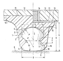
- the left half of the drawing shows a gripping element molded onto the outsole and the right half of the drawing shows a gripping element which can be fastened in the sole and thus also released again.
- the gripping element 1 consists of a lug or lug-shaped substructure 2 made of rigid, elastic plastic, in particular of polyurethane, polyimide, polyamide, polycarbonate, polyethylene, polypropylene or the like. Or also of mixtures of these materials. In principle, these materials can also have reinforcements or stiffeners made of glass fibers, carbon fibers or the like. This increases the bending stiffness and the hardness of the tunnel-shaped substructure 2.
- the tunnel-shaped substructure 2 or the column supports preferably have a hardness of 70 to 80 Shore A, preferably 75 Shore A. Such a lug-shaped substructure 2 also significantly reduces the lug pressure on the foot of the shoe wearer.
- An insert 3 made of hard metal or ceramic is inserted in the tunnel-shaped substructure 2, preferably cast or extrusion-coated with the plastic of the tunnel-shaped substructure 2.
- the size of the insert 3 is such that the ratio of diameter D to total height H is at least about 1: 0.75 to about 1: 1.8.
- the insert has a constriction E in the middle area.
- the insert 3 is divided into a tread part 4, said constriction E and a fastening part 5.
- the constriction E does not necessarily have to be in the middle of the total height H of the insert 3, but it can in principle be shifted somewhat downwards or upwards. In particular, the constriction E can be moved upwards to such an extent that it comes to lie approximately in the middle of the fastening part 5.
- the height of the constriction E is expediently about 25% to 60% of the total height H of the insert 3.
- the smallest diameter e of the constriction E is approximately 75% to 45% of the diameter D of the tread part 4.
- the inner surface 6 of the insert 3, that is the surface of the fastening part 5 can be flat or curved. It preferably has at least approximately the shape of a spherical cap, the radius R of which is smaller, in particular substantially smaller than the total height H of the insert 3. This gives a type of ball joint, so that the insert 3 can be deflected even more elastically on all sides with elastic deformation of the stud 2 , but due to the shape of the constriction E is not triggered from the tunnel 2.
- the size of the radius R is preferably approximately 80% to 50% of the total height H of the insert 3.
- the adjacent parts that is to say the tread part 4 - constriction E on the one hand and constriction E - fastening part 5 on the other hand merge into one another through the largest possible roundings in an S shape.
- the route 7 between the tread part 4 and constriction E are straight or slightly curved outwards, i.e. they are convex.
- the tangent to the turning point between tread part 4 and constriction E or to section 7 preferably includes an angle ⁇ of approximately 40 ° to 75 ° with tread plane 8. This gives a good contact surface in the lug-shaped gripping element 1.
- the diameter d of the fastening part 5 is advantageously approximately 75% to 120% of the diameter D of the tread part 4.
- the tread surface 9 of the tread part 4 is slightly curved outwards and rounded at the edge 10.
- the stud 2 can be molded onto the sole 12 or onto a special part of the outsole 12.1, for example glued on, cast on or molded on.
- a metal plate 13 with an attached stud 14, for example in the form of a threaded stud is attached to the stud base 11, preferably glued on or molded on, as the right half of the figure shows.
- the stud has 2 recesses 15 of known type for a turning tool for screwing in and unscrewing the same. Recesses can also be provided on the metal plate 13, if necessary additionally.
- the stud 2 is designed as a cylinder, but advantageously as a truncated cone with a smaller base 16 pointing outwards.
- the central angle of the cone is then about 5 ° to 40 °, in particular 10 ° to 20 °.
- the material used is hard metal, for example based on chrome, nickel, titanium or tungsten or ceramic based on metal oxides, in particular the metals aluminum, zirconium, silicon, tungsten, titanium or mixtures thereof or else metal carbides or metal nitrides, in particular based on aluminum, silicon, titanium, zirconium or mixtures thereof.
- the gripping elements designed according to the invention are particularly suitable for outdoor sports on hard, aggressive floors. Preferred areas of application are sports shoes for team sports, such as football, hockey, baseball or the like. In this case, the gripping elements have the lug shape shown in the drawing.
Landscapes
- Footwear And Its Accessory, Manufacturing Method And Apparatuses (AREA)
Abstract
Description
- Die vorliegende Erfindung bezieht sich auf ein Greifelement für Sportschuhe gemäß dem Oberbegriff des Anspruches 1.
- Ein derartiges Greifelement ist beispielsweise aus der DE-OS 32 33 900 bekannt. Dort besitzt der Einsatz aus Oxydkeramik bei einer Ausführungsart die Form einer Scheibe mit nach außen gewölbter Auftrittsfläche und plan ausgebildeter innerer Oberfläche. Im Abstand zu der planen inneren Oberfläche ist eine plane Fläche eines Befestigungszapfens vorgesehen.
- Bei einer anderen Ausführungsform ist der Einsatz aus Oxydkeramik annähernd als Spitzkegel ausgebildet, der innen einen mit Aussparungen versehenen Flansch aufweist. Letzerer ist mit Kunststoff umspritzt und in die Sohle eingelassen.
- Der aus der DE-PS 35 32 607 bekannte Einsatz aus Keramik besitzt mit Ausnahmen der planen inneren Oberfläche die gleiche Form wie die genannte Scheibe und ist mit der inneren, leicht nach außen gewölbten Oberfläche an einen gegengleich ausgebildeten Metall-Befestigungsbolzen angelötet oder angeklebt.
- All diesen Ausführungen ist gemeinsam, daß der Einsatz aus Keramik, insbesondere Oxydkeramik, praktisch vollkommen starr im stollenförmigen Unterbau befestigt ist. Dies trifft insbesondere für die aus der DE-PS 35 32 607 bekannte Ausführung zu, bei der der Keramikeinsatz auf einem Bolzen aufgelötet ist.
- Bekanntlich ist Keramik sehr abriebfest, weshalb dieses Material für Greifelemente in bestimmten Anwendungsfällen besonders geeignet ist. Keramik kann auch sehr hohe Druckbeanspruchtungen aushalten. Jedoch ist Keramik und sind auc Hartemetalle sehr spröde, so daß sie gegen Scherkräfte und Biegekräfte relativ empfindlich sind.
- Mit der vorliegenden Erfindung soll die Aufgabe gelöst werden, einen Einsatz für Greifelemente der genannten Art so auszubilden, daß die an der Auftrittsfläche auftretenden Scher- und Biegekräfte nicht zum Abplatzen von Materialteilen des Einsatzes führen können.
- Gelöst wird diese Aufgabe durch die im Kennzeichen des Anspruches 1 angegebenen Merkmale.
- Durch die erfindungsgemäße Ausbildung des Stolleneinsatzes mit dessen Einschnürung ist der Einsatz im stollenförmigen Unterbau fest verankert. Trotzdem ist der Einsatz beim Auftreten größerer Kräfte, insbesondere Scherkräfte, in den Randzonen noch in und mit dem Stollen elastisch auslenkbar, da die Einschnürung eine Art Lager bildet. Hierdurch kann beispielsweise bei unter einem Winkel von 30° bis 70° am Rand einwirkenden Kräften der Einsatz elastischen federnd ausweichen, so daß die Stoßkräfte bzw. -belastungen gemindert werden. Dadurch wird die Gefahr des Absprengens von Material, insbesondere im Randbereich des Einsatzes, stark verringert.
- Weitere vorteilhafte Einzelheiten der Erfindung sind in den Unteransprüchen angegeben und werden nachfolgend anhand in der Zeichnung veranschaulichter Ausführungsbeispiele näher beschrieben.
- Dabei zeigt die linke Hälfte der Zeichnung ein an der Laufsohle angeformtes Greifelement und die rechte Hälfte der Zeichnung ein in der Sohle befestigbares und damit auch wieder lösbares Greifelement.
- Das Greifelement 1 besteht aus einem Stollen bzw. stollenförmigen Unterbau 2 aus biegesteifem, elastischem Kunststoff, insbesondere aus Polyurethan, Polyimid, Polyamid, Polycarbonat, Polyäthylen, Polypropylen oder dgl. oder auch aus Mischungen dieser Materialien. Grundsätzlich können diese Materialien auch Verstärkungen bzw. Versteifungen aus Glasfasern, Carbonfasern oder dgl. aufweisen. Damit wird die Biegesteifigkeit und die Härte des stollenförmigen Unterbaus 2 erhöht. Der stollenförmige Unterbau 2 bzw. die Stllenträger weisen bevorzugt eine Härte von 70 bis 80 Shore A, vorzugsweise von 75 Shore A auf. Ein derartiger stollenförmiger Unterbau 2 verringert außerdem den Stollendruck auf den Fuß des Schuhträgers wesentlich.
- In dem stollenförmigen Unterbau 2 ist ein Einsatz 3 aus Hartmetall oder aus Keramik eingesetzt, vorzugsweise mit dem Kunststoff des stollenförmigen Unterbaus 2 umgossen oder umspritzt.
- Die Größe des Einsatzes 3 ist so bemessen, daß das Verhältnis von Durchmesser D zu Gesamthöhe H wenigstens etwa 1 : 0,75 bis zu etwa 1 : 1,8 beträgt. Der Einsatz weist etwa im mittleren Bereich eine Einschnürung E auf. Hierdurch ist der Einsatz 3 in einen Auftrittsteil 4, in die besagte Einschnürung E und in einen Befestigungsteil 5 unterteilt. Die Einschnürung E muß nicht unbedingt in der Mitte der Gesamthöhe H des Einsatzes 3 liegen, sondern sie kann grundsätzlich etwas nach unten oder nach oben verschoben sein. Insbesondere kann die Einschnürung E soweit nach oben verlegt werden, daß sie etwa in der Mitte des Befestigungsteils 5 zu liegen kommt. Die Höhe der Einschnürung E beträgt zweckmäßig etwa 25 % bis 60 % der Gesamthöhe H des Einsatzes 3. Der kleinste Durchmesser e der Einschnürung E beträgt etwa 75 % bis 45 % des Durchmessers D des Auftrittsteiles 4. Die innere Oberfläche 6 des Einsatzes 3, also die Oberfläche des Befestigungsteils 5, kann eben oder gewölbt sein. Vorzugsweise besitzt sie wenigstens annähernd die Form einer Kugelkalotte, deren Radius R kleiner, insbesondere wesentlich kleiner ist als die Gesamthöhe H des Einsatzes 3. Hierdurch erhält man eine Art Kugelgelenk, so daß der Einsatz 3 unter elastischer Verformung des Stollens 2 noch besser allseitig elastische auslenkbar, aber infolge der Form der Einschnürung E nicht aus dem Stollen 2 auslösbar ist. Vorzugsweise beträgt die Größe des Radius R etwa 80 % bis 50 % der Gesamthöhe H des Einsatzes 3.
- Um einen Bruch im Bereich der Einschnürung E zu vermeiden, gehen die angrenzenden Teile, also Auftrittsteil 4 - Einschnürung E einerseits und Einschnürung E - Befestigungsteil 5 andererseits durch möglichst große Rundungen in S-Form ineinander über.
- Dabei kann die Strecke 7 zwischen Auftrittsteil 4 und Einschnürung E ein Stück gerade verlaufen oder leicht nach außen gewölbt, also konvex sein. Die Tangente an den Wendepunkt zwischen Auftrittsteil 4 und Einschnürung E oder an die Strecke 7 schließt vorzugsweise einen winkel α von etwa 40° bis 75° mit der Auftrittsebene 8 ein. Hierdurch erhält man eine gute Auflagefläche im stollenförmigen Greifelement 1.
- Der Durchmesser d des Befestugungsteils 5 beträgt vorteilhaft etwa 75 % bis 120 % des Durchmessers D des Auftrittsteiles 4. Die Auftrittsfläche 9 des Auftrittsteiles 4 ist nach außen leicht gewölbt und am Rand 10 abgerundet. Der Abstand a = N - H zwischen Einsatz 3 und Stollengrund 11 beträgt etwa 1,5 mm bis 8 mm, insbesondere 1,5 mm bis 3 mm.
- Der Stollen 2 kann gemäß der linken Hälfte der Figur an der Sohle 12 oder an einem besonderen Teil der Laufsohle 12.1 angeformt sein, beispielsweise aufgeklebt, angegossen oder angespritzt. Bei an der Sohle 12 befestigbarem Stollen 2, ist, wie die rechte Hälfte der Figur zeigt, auf den Stollengrund 11 eine Metallplatte 13 mit einem daran angebrachten, beispielsweise als Gewindezapfen ausgebildeten Befestigungszapfen 14 aufgebracht, vorzugsweise aufgeklebt oder mit angeformt. In diesem Fall besitzt der Stollen 2 Aussparungen 15 bekannter Art für ein Drehwerkzeug zum Ein- und Ausschrauben desselben. Aussparungen können auch an der Metallplatte 13, gegebenenfalls zusätzlich, vorgesehen sein.
- Der Stollen 2 ist als Zylinder, vorteilhaft aber als Kegelstumpf mit nach außen weisender kleinerer Basis 16 Kegelstumpf mit nach außen weisender kleinerer Basis 16 ausgebildet. Der Zentriwinkel des Kegels beträgt dann etwa 5° bis 40°, insbesondere 10° bis 20° .
- Als Material für den Einsatz dient Hartmetall, beispielsweise auf Chrom-, Nickel-, Titan- oder Wolframbasis oder Keramik auf der Basis von Metalloxiden, insbesondere der Metalle Aluminium, Zirkon, Silizium, Wolfram, Titan oder Mischungen derselben oder aber auch Metallkarbide oder Metallnitride, insbesondere auf der Basis von Aluminium, Silizium, Titan, Zirkon oder Mischungen derselben.
- Die erfindungsgemäß ausgebildeten Greifelemente eignen sich insbesondere für Sportarten im Freien auf harten, agressiven Böden. Bevorzugter Anwendungsbereich sind Sportschuhe für Mannschaftssportarten, wie Fußball, Hockey, Baseball oder dgl.. In diesem Falle besitzen die Greifelemente die zeichnerisch dargestellte Stollenform.
Claims (17)
Applications Claiming Priority (2)
| Application Number | Priority Date | Filing Date | Title |
|---|---|---|---|
| DE19873706068 DE3706068A1 (de) | 1987-02-25 | 1987-02-25 | Greifelement fuer sportschuhe |
| DE3706068 | 1987-02-25 |
Publications (2)
| Publication Number | Publication Date |
|---|---|
| EP0280108A2 true EP0280108A2 (de) | 1988-08-31 |
| EP0280108A3 EP0280108A3 (de) | 1989-12-27 |
Family
ID=6321751
Family Applications (1)
| Application Number | Title | Priority Date | Filing Date |
|---|---|---|---|
| EP88101855A Ceased EP0280108A3 (de) | 1987-02-25 | 1988-02-09 | Greifelement für Sportschuhe |
Country Status (4)
| Country | Link |
|---|---|
| US (1) | US4833796A (de) |
| EP (1) | EP0280108A3 (de) |
| JP (1) | JPS63226301A (de) |
| DE (1) | DE3706068A1 (de) |
Cited By (2)
| Publication number | Priority date | Publication date | Assignee | Title |
|---|---|---|---|---|
| WO1999022618A1 (de) * | 1997-10-30 | 1999-05-14 | Peter Greiner | Keramik-greifelement für sportschuhe |
| US6112433A (en) * | 1997-10-30 | 2000-09-05 | Greiner; Peter | Ceramic gripping element for sports shoes |
Families Citing this family (64)
| Publication number | Priority date | Publication date | Assignee | Title |
|---|---|---|---|---|
| US5426873A (en) * | 1990-08-01 | 1995-06-27 | Macneill Engineering Company, Inc. | Cleat and process for making same |
| US5617653A (en) * | 1991-04-15 | 1997-04-08 | Andrew S. Walker | Break-away cleat assembly for athletic shoe |
| FR2681515B1 (fr) * | 1991-09-19 | 1993-12-24 | Patrick Int | Semelage a protuberances pour chaussures de sport. |
| US5259129A (en) | 1992-04-24 | 1993-11-09 | Warm Springs Golf Club, Inc. | Winter golf shoe spikes |
| WO1994013164A1 (en) * | 1992-12-10 | 1994-06-23 | Nike International Ltd. | Bonding of rubber to plastic in footwear |
| US5377431A (en) * | 1993-06-15 | 1995-01-03 | Walker; Andrew S. | Directionally yieldable cleat assembly |
| US5628129A (en) * | 1995-06-06 | 1997-05-13 | Nike, Inc. | Shoe sole having detachable traction members |
| JP2863466B2 (ja) * | 1995-06-14 | 1999-03-03 | 美津濃株式会社 | 陸上スパイク靴用ソール |
| US5761833A (en) * | 1995-12-22 | 1998-06-09 | Softspikes, Inc. | Athletic shoe traction system for use on turf |
| US5832636A (en) * | 1996-09-06 | 1998-11-10 | Nike, Inc. | Article of footwear having non-clogging sole |
| CA2210771C (en) * | 1996-12-20 | 2000-12-05 | Softspikes, Inc. | Golf cleat |
| US5926974A (en) * | 1997-01-17 | 1999-07-27 | Nike, Inc. | Footwear with mountain goat traction elements |
| US5906059A (en) * | 1997-09-03 | 1999-05-25 | Lisco, Inc. | Composite cleat for athletic shoe |
| US6138386A (en) * | 1997-09-03 | 2000-10-31 | Spalding Sports Worldwide, Inc. | Composite cleat for athletic shoe |
| US6381878B1 (en) | 1997-09-03 | 2002-05-07 | Spalding Sports Worldwide, Inc. | Composite cleat for athletic shoe |
| US6023860A (en) * | 1997-12-11 | 2000-02-15 | Softspikes, Inc. | Athletic shoe cleat |
| USD424384S (en) * | 1999-01-22 | 2000-05-09 | Spalding Sports Worldwide, Inc. | Athletic shoe cleat |
| USD421677S (en) * | 1999-05-26 | 2000-03-21 | Howard Silagy | Shoe stud |
| US6948264B1 (en) | 2000-04-26 | 2005-09-27 | Lyden Robert M | Non-clogging sole for article of footwear |
| GB0027750D0 (en) * | 2000-11-14 | 2000-12-27 | Trisport Ltd | Studded footwear |
| JP2002315605A (ja) * | 2001-04-19 | 2002-10-29 | Minebea Co Ltd | スタッド及びスタッド付きシューズ |
| US6834445B2 (en) | 2002-07-16 | 2004-12-28 | Softspikes, Llc | Shoe cleat with improved traction |
| US6834446B2 (en) | 2002-08-27 | 2004-12-28 | Softspikes, Llc | Indexable shoe cleat with improved traction |
| DE10241153B3 (de) | 2002-09-05 | 2004-04-08 | Adidas International Marketing B.V. | Stollen und Schuh |
| US6904707B2 (en) * | 2003-07-01 | 2005-06-14 | Softspikes, Llc | Indexable shoe cleat with improved traction |
| CA2498400C (en) | 2003-08-11 | 2009-10-06 | Softspikes, Llc. | Shoe cleat |
| CN1890906A (zh) * | 2003-08-27 | 2007-01-03 | 美商内数位科技公司 | 多重使用者正交分频多任务系统的实时服务的次载波及位分配 |
| US20100192421A1 (en) * | 2004-07-14 | 2010-08-05 | Dashamerica, Inc. D/B/A Pearl Izumi Usa, Inc. | Composite sole |
| US7401424B2 (en) * | 2004-07-14 | 2008-07-22 | Dashamerica, Inc. | Composite outsole |
| US7549236B2 (en) * | 2006-03-09 | 2009-06-23 | New England Footwear, Llc | Footwear with independent suspension and protection |
| USD583135S1 (en) | 2006-05-12 | 2008-12-23 | New England Footwear, Llc | Portion of a footwear sole |
| USD579185S1 (en) | 2006-05-12 | 2008-10-28 | New England Footwear, Llc | Footwear sole |
| JP5323065B2 (ja) * | 2007-06-20 | 2013-10-23 | テイラー メイド ゴルフ カンパニー インコーポレイテッド | 低プロファイルソールを有するトラクション部材を有する履物 |
| US8056267B2 (en) * | 2008-05-30 | 2011-11-15 | Nike, Inc. | Article of footwear with cleated sole assembly |
| US8256145B2 (en) | 2008-09-26 | 2012-09-04 | Nike, Inc. | Articles with retractable traction elements |
| US8079160B2 (en) | 2008-09-26 | 2011-12-20 | Nike, Inc. | Articles with retractable traction elements |
| BRPI1014856A2 (pt) | 2009-04-02 | 2016-05-03 | Nike International Ltd | "elementos de tração" |
| US8616892B2 (en) * | 2009-04-02 | 2013-12-31 | Nike, Inc. | Training system for an article of footwear with a traction system |
| US8632342B2 (en) | 2009-05-28 | 2014-01-21 | Nike, Inc. | Training system for an article of footwear |
| US8573981B2 (en) | 2009-05-29 | 2013-11-05 | Nike, Inc. | Training system for an article of footwear with a ball control portion |
| US8453354B2 (en) * | 2009-10-01 | 2013-06-04 | Nike, Inc. | Rigid cantilevered stud |
| US8533979B2 (en) * | 2010-02-18 | 2013-09-17 | Nike, Inc. | Self-adjusting studs |
| US8322051B2 (en) * | 2010-02-23 | 2012-12-04 | Nike, Inc. | Self-adjusting studs |
| NZ604514A (en) | 2010-06-17 | 2014-06-27 | Dashamerica Inc D/B/A Pearl Izumi Usa Inc | Dual rigidity shoe sole |
| US9210967B2 (en) | 2010-08-13 | 2015-12-15 | Nike, Inc. | Sole structure with traction elements |
| US8529267B2 (en) | 2010-11-01 | 2013-09-10 | Nike, Inc. | Integrated training system for articles of footwear |
| US8713819B2 (en) | 2011-01-19 | 2014-05-06 | Nike, Inc. | Composite sole structure |
| CA2830641C (en) | 2011-03-25 | 2018-01-02 | Dashamerica, Inc. D/B/A Pearl Izumi Usa, Inc. | Flexible shoe sole |
| US9504293B2 (en) | 2011-04-18 | 2016-11-29 | Nike, Inc. | Outsole with extendable traction elements |
| US9220320B2 (en) | 2011-09-16 | 2015-12-29 | Nike, Inc. | Sole arrangement with ground-engaging member support features |
| US8966787B2 (en) | 2011-09-16 | 2015-03-03 | Nike, Inc. | Orientations for footwear ground-engaging member support features |
| US9138027B2 (en) | 2011-09-16 | 2015-09-22 | Nike, Inc. | Spacing for footwear ground-engaging member support features |
| US8806779B2 (en) | 2011-09-16 | 2014-08-19 | Nike, Inc. | Shaped support features for footwear ground-engaging members |
| US9402442B2 (en) | 2012-04-27 | 2016-08-02 | Nike, Inc. | Sole structure and article of footwear including same |
| USD712122S1 (en) | 2012-07-25 | 2014-09-02 | Dash America, Inc. | Shoe sole |
| USD713135S1 (en) | 2012-07-25 | 2014-09-16 | Dashamerica, Inc. | Shoe sole |
| USD710079S1 (en) | 2012-07-25 | 2014-08-05 | Dashamerica, Inc. | Shoe sole |
| USD715522S1 (en) | 2012-07-25 | 2014-10-21 | Dashamerica, Inc. | Shoe sole |
| USD709275S1 (en) | 2012-07-25 | 2014-07-22 | Dash American, Inc. | Shoe sole |
| USD711083S1 (en) | 2012-07-25 | 2014-08-19 | Dashamerica, Inc. | Shoe sole |
| US9032645B2 (en) | 2012-07-30 | 2015-05-19 | Nike, Inc. | Support features for footwear ground engaging members |
| US10010139B2 (en) | 2013-08-07 | 2018-07-03 | Nike, Inc. | Method for making a cleated plate member and apparatus |
| USD761086S1 (en) * | 2013-08-13 | 2016-07-12 | Trek Bicycle Corporation | Cleat |
| US20220361631A1 (en) * | 2021-05-17 | 2022-11-17 | Ronald Lawrence Somers | Wear-resistant, fully embedded node for extending the life of polyurethane used in restoring shoes |
Family Cites Families (11)
| Publication number | Priority date | Publication date | Assignee | Title |
|---|---|---|---|---|
| US2697288A (en) * | 1952-01-17 | 1954-12-21 | Clarke L Wilcox | Golf shoe cleat |
| US3054197A (en) * | 1958-04-21 | 1962-09-18 | John T Riddell Inc | Snap-on shoe cleat asembly |
| JPS4821840U (de) * | 1971-07-26 | 1973-03-13 | ||
| DE2313646C3 (de) * | 1973-03-19 | 1980-08-14 | Ludwig 7403 Ammerbuch Sailer | Stollen für Sportschuhe, insbesondere für Fußballschuhe |
| US4380878A (en) * | 1980-09-26 | 1983-04-26 | Keds Corporation | Outsole |
| DE3233900A1 (de) * | 1982-09-13 | 1984-03-15 | Sportartikelfabrik Karl Uhl Gmbh, 7460 Balingen | Sportschuhsohle mit greifelementen |
| BR8503313A (pt) * | 1984-07-19 | 1986-04-01 | Dassler Puma Sportschuh | Sapato esportivo com uma sola apresentando elementos pegadores substituiveis |
| JPS61244303A (ja) * | 1985-04-19 | 1986-10-30 | モリト株式会社 | ゴルフ靴用スパイク |
| DE3660702D1 (en) * | 1985-07-27 | 1988-10-20 | Adidas Sportschuhe | Stud for a sports shoe |
| DE3603127C1 (de) * | 1986-02-01 | 1987-06-25 | Adidas Sportschuhe | Keramik-Greifelement fuer Sportschuhe |
| DE8602644U1 (de) * | 1986-02-01 | 1986-03-27 | adidas Sportschuhfabriken Adi Dassler Stiftung & Co KG, 8522 Herzogenaurach | Keramik-Greifelement für Sportschuhe |
-
1987
- 1987-02-25 DE DE19873706068 patent/DE3706068A1/de not_active Withdrawn
-
1988
- 1988-02-09 EP EP88101855A patent/EP0280108A3/de not_active Ceased
- 1988-02-22 US US07/158,645 patent/US4833796A/en not_active Expired - Fee Related
- 1988-02-24 JP JP63039775A patent/JPS63226301A/ja active Pending
Cited By (2)
| Publication number | Priority date | Publication date | Assignee | Title |
|---|---|---|---|---|
| WO1999022618A1 (de) * | 1997-10-30 | 1999-05-14 | Peter Greiner | Keramik-greifelement für sportschuhe |
| US6112433A (en) * | 1997-10-30 | 2000-09-05 | Greiner; Peter | Ceramic gripping element for sports shoes |
Also Published As
| Publication number | Publication date |
|---|---|
| US4833796A (en) | 1989-05-30 |
| EP0280108A3 (de) | 1989-12-27 |
| JPS63226301A (ja) | 1988-09-21 |
| DE3706068A1 (de) | 1988-09-08 |
Similar Documents
| Publication | Publication Date | Title |
|---|---|---|
| EP0280108A2 (de) | Greifelement für Sportschuhe | |
| DE68910739T2 (de) | Bohrer. | |
| EP0090884B1 (de) | Laufsohle mit Nocken für Sportschuhe, insbesondere Fussballschuhe | |
| DE9214782U1 (de) | Sportschuh mit einer Laufsohle mit Halterungseinsätzen zur Halterung von Greifelementen | |
| EP0081067A2 (de) | Sportschuh, insbesondere Fussballschuh | |
| EP0210362B1 (de) | Stollenförmiges Greifelement für Sportschuhe | |
| DE102009041816A1 (de) | Unterlegplatte für die Befestigung einer Schiene auf einem festen Untergrund und Befestigung einer Schiene | |
| EP1497567B1 (de) | Selbstsichernde befestigungseinrichtung | |
| DE202005016610U1 (de) | Wendeschneidplatte für einen Drehmeißel | |
| DE3233900A1 (de) | Sportschuhsohle mit greifelementen | |
| DE3707297A1 (de) | Nasenplaettchen fuer brillen | |
| DE102007000607A1 (de) | Gewindefurchende Schraube | |
| DE112008000819B4 (de) | Schneideinsatz, Schneidwerkzeug und Verfahren zum Schneiden von Arbeitsmaterial unter Verwendung des Schneidwerkzeugs | |
| EP1679484A1 (de) | Vorrichtung zur Befestigung von ballistischen Schutzelementen | |
| DE69903023T2 (de) | Stossdämpfendes hufeisen und verfahren zur herstellung eines solchen hufeisens | |
| EP1687156A1 (de) | Spike für fahrzeugreifen | |
| DE8702904U1 (de) | Greifelement für Sportschuhe | |
| EP0356637B1 (de) | Sportschuh, insbesondere Fussballschuh | |
| DE2810363A1 (de) | Sportschuh insbesondere fussballschuh mit auswechselbaren stollen | |
| DE3442747A1 (de) | Aus zahn und adapter bestehender werkzeugsatz | |
| DE2801983A1 (de) | Schraubstollen fuer sportschuhe, insbesondere fussballschuhe | |
| DE2334329A1 (de) | Gleitlager | |
| DE2310183C3 (de) | Gleitschutzpuffer für Unterarmgehstützen | |
| DE9318531U1 (de) | Einsatzkörper für die Auflagefläche von Fußschwellen bei Leiteinrichtungen für den Straßenverkehr | |
| DE3300330A1 (de) | Sportschuh mit haltestegen und auswechselbaren beschlaegen |
Legal Events
| Date | Code | Title | Description |
|---|---|---|---|
| PUAI | Public reference made under article 153(3) epc to a published international application that has entered the european phase |
Free format text: ORIGINAL CODE: 0009012 |
|
| AK | Designated contracting states |
Kind code of ref document: A2 Designated state(s): AT BE CH DE ES FR GB IT LI NL SE |
|
| PUAL | Search report despatched |
Free format text: ORIGINAL CODE: 0009013 |
|
| AK | Designated contracting states |
Kind code of ref document: A3 Designated state(s): AT BE CH DE ES FR GB IT LI NL SE |
|
| 17P | Request for examination filed |
Effective date: 19900612 |
|
| 17Q | First examination report despatched |
Effective date: 19920123 |
|
| STAA | Information on the status of an ep patent application or granted ep patent |
Free format text: STATUS: THE APPLICATION HAS BEEN REFUSED |
|
| 18R | Application refused |
Effective date: 19930404 |