EP0280112A1 - Verfahren und Vorrichtung zum Verbinden zweier oder mehrerer Teile - Google Patents
Verfahren und Vorrichtung zum Verbinden zweier oder mehrerer Teile Download PDFInfo
- Publication number
- EP0280112A1 EP0280112A1 EP88101895A EP88101895A EP0280112A1 EP 0280112 A1 EP0280112 A1 EP 0280112A1 EP 88101895 A EP88101895 A EP 88101895A EP 88101895 A EP88101895 A EP 88101895A EP 0280112 A1 EP0280112 A1 EP 0280112A1
- Authority
- EP
- European Patent Office
- Prior art keywords
- stack
- jig
- members
- bonding
- pressing
- Prior art date
- Legal status (The legal status is an assumption and is not a legal conclusion. Google has not performed a legal analysis and makes no representation as to the accuracy of the status listed.)
- Granted
Links
- 238000000034 method Methods 0.000 title claims description 18
- 239000000463 material Substances 0.000 claims abstract description 24
- 238000003825 pressing Methods 0.000 claims description 59
- 238000010438 heat treatment Methods 0.000 claims description 24
- 239000000919 ceramic Substances 0.000 claims description 14
- 229910052782 aluminium Inorganic materials 0.000 claims description 12
- XAGFODPZIPBFFR-UHFFFAOYSA-N aluminium Chemical compound [Al] XAGFODPZIPBFFR-UHFFFAOYSA-N 0.000 claims description 11
- 239000002344 surface layer Substances 0.000 claims description 11
- 239000007769 metal material Substances 0.000 claims description 6
- 229910000838 Al alloy Inorganic materials 0.000 claims description 4
- 239000010410 layer Substances 0.000 claims description 3
- 229910000676 Si alloy Inorganic materials 0.000 claims description 2
- CSDREXVUYHZDNP-UHFFFAOYSA-N alumanylidynesilicon Chemical compound [Al].[Si] CSDREXVUYHZDNP-UHFFFAOYSA-N 0.000 claims description 2
- 239000012792 core layer Substances 0.000 claims description 2
- 238000002844 melting Methods 0.000 claims description 2
- 230000008018 melting Effects 0.000 claims description 2
- 238000004519 manufacturing process Methods 0.000 abstract description 8
- 239000002131 composite material Substances 0.000 abstract description 3
- 239000000047 product Substances 0.000 description 16
- 238000010008 shearing Methods 0.000 description 12
- 229910000831 Steel Inorganic materials 0.000 description 7
- 239000010959 steel Substances 0.000 description 7
- XKRFYHLGVUSROY-UHFFFAOYSA-N Argon Chemical compound [Ar] XKRFYHLGVUSROY-UHFFFAOYSA-N 0.000 description 6
- 238000010586 diagram Methods 0.000 description 5
- 239000010955 niobium Substances 0.000 description 5
- 102220061996 rs786203944 Human genes 0.000 description 5
- 238000005452 bending Methods 0.000 description 4
- RYGMFSIKBFXOCR-UHFFFAOYSA-N Copper Chemical compound [Cu] RYGMFSIKBFXOCR-UHFFFAOYSA-N 0.000 description 3
- 229910052581 Si3N4 Inorganic materials 0.000 description 3
- 239000004411 aluminium Substances 0.000 description 3
- 229910052786 argon Inorganic materials 0.000 description 3
- 239000012298 atmosphere Substances 0.000 description 3
- 229910052802 copper Inorganic materials 0.000 description 3
- 239000010949 copper Substances 0.000 description 3
- 239000007789 gas Substances 0.000 description 3
- 229910052751 metal Inorganic materials 0.000 description 3
- 239000002184 metal Substances 0.000 description 3
- HQVNEWCFYHHQES-UHFFFAOYSA-N silicon nitride Chemical compound N12[Si]34N5[Si]62N3[Si]51N64 HQVNEWCFYHHQES-UHFFFAOYSA-N 0.000 description 3
- 229910000975 Carbon steel Inorganic materials 0.000 description 2
- 229910000861 Mg alloy Inorganic materials 0.000 description 2
- 229910000589 SAE 304 stainless steel Inorganic materials 0.000 description 2
- 229910052799 carbon Inorganic materials 0.000 description 2
- 239000010962 carbon steel Substances 0.000 description 2
- 229910052804 chromium Inorganic materials 0.000 description 2
- 238000011109 contamination Methods 0.000 description 2
- 230000000694 effects Effects 0.000 description 2
- 239000011572 manganese Substances 0.000 description 2
- 229910052750 molybdenum Inorganic materials 0.000 description 2
- 239000010963 304 stainless steel Substances 0.000 description 1
- OKTJSMMVPCPJKN-UHFFFAOYSA-N Carbon Chemical compound [C] OKTJSMMVPCPJKN-UHFFFAOYSA-N 0.000 description 1
- 229910001209 Low-carbon steel Inorganic materials 0.000 description 1
- ZOKXTWBITQBERF-UHFFFAOYSA-N Molybdenum Chemical compound [Mo] ZOKXTWBITQBERF-UHFFFAOYSA-N 0.000 description 1
- BQCADISMDOOEFD-UHFFFAOYSA-N Silver Chemical compound [Ag] BQCADISMDOOEFD-UHFFFAOYSA-N 0.000 description 1
- RTAQQCXQSZGOHL-UHFFFAOYSA-N Titanium Chemical compound [Ti] RTAQQCXQSZGOHL-UHFFFAOYSA-N 0.000 description 1
- 229910045601 alloy Inorganic materials 0.000 description 1
- 239000000956 alloy Substances 0.000 description 1
- -1 aluminum-silicon-magnesium Chemical compound 0.000 description 1
- 239000012300 argon atmosphere Substances 0.000 description 1
- 230000000712 assembly Effects 0.000 description 1
- 238000000429 assembly Methods 0.000 description 1
- 229910000963 austenitic stainless steel Inorganic materials 0.000 description 1
- 238000005219 brazing Methods 0.000 description 1
- 229910010293 ceramic material Inorganic materials 0.000 description 1
- 238000002485 combustion reaction Methods 0.000 description 1
- 230000001627 detrimental effect Effects 0.000 description 1
- 230000003467 diminishing effect Effects 0.000 description 1
- 230000008030 elimination Effects 0.000 description 1
- 238000003379 elimination reaction Methods 0.000 description 1
- 230000001771 impaired effect Effects 0.000 description 1
- 238000003754 machining Methods 0.000 description 1
- 229910052748 manganese Inorganic materials 0.000 description 1
- 239000011733 molybdenum Substances 0.000 description 1
- 229910052759 nickel Inorganic materials 0.000 description 1
- 229910052758 niobium Inorganic materials 0.000 description 1
- GUCVJGMIXFAOAE-UHFFFAOYSA-N niobium atom Chemical compound [Nb] GUCVJGMIXFAOAE-UHFFFAOYSA-N 0.000 description 1
- 230000003647 oxidation Effects 0.000 description 1
- 238000007254 oxidation reaction Methods 0.000 description 1
- 238000007747 plating Methods 0.000 description 1
- 229910052710 silicon Inorganic materials 0.000 description 1
- HBMJWWWQQXIZIP-UHFFFAOYSA-N silicon carbide Chemical compound [Si+]#[C-] HBMJWWWQQXIZIP-UHFFFAOYSA-N 0.000 description 1
- 229910052709 silver Inorganic materials 0.000 description 1
- 239000004332 silver Substances 0.000 description 1
- 229910000679 solder Inorganic materials 0.000 description 1
- 239000013589 supplement Substances 0.000 description 1
- 239000010936 titanium Substances 0.000 description 1
- 229910052719 titanium Inorganic materials 0.000 description 1
- 239000011800 void material Substances 0.000 description 1
- 238000003466 welding Methods 0.000 description 1
Images


Classifications
-
- C—CHEMISTRY; METALLURGY
- C04—CEMENTS; CONCRETE; ARTIFICIAL STONE; CERAMICS; REFRACTORIES
- C04B—LIME, MAGNESIA; SLAG; CEMENTS; COMPOSITIONS THEREOF, e.g. MORTARS, CONCRETE OR LIKE BUILDING MATERIALS; ARTIFICIAL STONE; CERAMICS; REFRACTORIES; TREATMENT OF NATURAL STONE
- C04B37/00—Joining burned ceramic articles with other burned ceramic articles or other articles by heating
- C04B37/02—Joining burned ceramic articles with other burned ceramic articles or other articles by heating with metallic articles
- C04B37/023—Joining burned ceramic articles with other burned ceramic articles or other articles by heating with metallic articles characterised by the interlayer used
- C04B37/026—Joining burned ceramic articles with other burned ceramic articles or other articles by heating with metallic articles characterised by the interlayer used consisting of metals or metal salts
-
- B—PERFORMING OPERATIONS; TRANSPORTING
- B23—MACHINE TOOLS; METAL-WORKING NOT OTHERWISE PROVIDED FOR
- B23K—SOLDERING OR UNSOLDERING; WELDING; CLADDING OR PLATING BY SOLDERING OR WELDING; CUTTING BY APPLYING HEAT LOCALLY, e.g. FLAME CUTTING; WORKING BY LASER BEAM
- B23K20/00—Non-electric welding by applying impact or other pressure, with or without the application of heat, e.g. cladding or plating
- B23K20/02—Non-electric welding by applying impact or other pressure, with or without the application of heat, e.g. cladding or plating by means of a press ; Diffusion bonding
-
- B—PERFORMING OPERATIONS; TRANSPORTING
- B23—MACHINE TOOLS; METAL-WORKING NOT OTHERWISE PROVIDED FOR
- B23K—SOLDERING OR UNSOLDERING; WELDING; CLADDING OR PLATING BY SOLDERING OR WELDING; CUTTING BY APPLYING HEAT LOCALLY, e.g. FLAME CUTTING; WORKING BY LASER BEAM
- B23K20/00—Non-electric welding by applying impact or other pressure, with or without the application of heat, e.g. cladding or plating
- B23K20/16—Non-electric welding by applying impact or other pressure, with or without the application of heat, e.g. cladding or plating with interposition of special material to facilitate connection of the parts, e.g. material for absorbing or producing gas
-
- B—PERFORMING OPERATIONS; TRANSPORTING
- B32—LAYERED PRODUCTS
- B32B—LAYERED PRODUCTS, i.e. PRODUCTS BUILT-UP OF STRATA OF FLAT OR NON-FLAT, e.g. CELLULAR OR HONEYCOMB, FORM
- B32B37/00—Methods or apparatus for laminating, e.g. by curing or by ultrasonic bonding
- B32B37/10—Methods or apparatus for laminating, e.g. by curing or by ultrasonic bonding characterised by the pressing technique, e.g. using action of vacuum or fluid pressure
-
- B—PERFORMING OPERATIONS; TRANSPORTING
- B32—LAYERED PRODUCTS
- B32B—LAYERED PRODUCTS, i.e. PRODUCTS BUILT-UP OF STRATA OF FLAT OR NON-FLAT, e.g. CELLULAR OR HONEYCOMB, FORM
- B32B37/00—Methods or apparatus for laminating, e.g. by curing or by ultrasonic bonding
- B32B37/10—Methods or apparatus for laminating, e.g. by curing or by ultrasonic bonding characterised by the pressing technique, e.g. using action of vacuum or fluid pressure
- B32B37/1054—Regulating the dimensions of the laminate, e.g. by adjusting the nip or platen gap
-
- B—PERFORMING OPERATIONS; TRANSPORTING
- B32—LAYERED PRODUCTS
- B32B—LAYERED PRODUCTS, i.e. PRODUCTS BUILT-UP OF STRATA OF FLAT OR NON-FLAT, e.g. CELLULAR OR HONEYCOMB, FORM
- B32B2315/00—Other materials containing non-metallic inorganic compounds not provided for in groups B32B2311/00 - B32B2313/04
- B32B2315/02—Ceramics
-
- C—CHEMISTRY; METALLURGY
- C04—CEMENTS; CONCRETE; ARTIFICIAL STONE; CERAMICS; REFRACTORIES
- C04B—LIME, MAGNESIA; SLAG; CEMENTS; COMPOSITIONS THEREOF, e.g. MORTARS, CONCRETE OR LIKE BUILDING MATERIALS; ARTIFICIAL STONE; CERAMICS; REFRACTORIES; TREATMENT OF NATURAL STONE
- C04B2237/00—Aspects relating to ceramic laminates or to joining of ceramic articles with other articles by heating
- C04B2237/02—Aspects relating to interlayers, e.g. used to join ceramic articles with other articles by heating
- C04B2237/12—Metallic interlayers
- C04B2237/121—Metallic interlayers based on aluminium
-
- C—CHEMISTRY; METALLURGY
- C04—CEMENTS; CONCRETE; ARTIFICIAL STONE; CERAMICS; REFRACTORIES
- C04B—LIME, MAGNESIA; SLAG; CEMENTS; COMPOSITIONS THEREOF, e.g. MORTARS, CONCRETE OR LIKE BUILDING MATERIALS; ARTIFICIAL STONE; CERAMICS; REFRACTORIES; TREATMENT OF NATURAL STONE
- C04B2237/00—Aspects relating to ceramic laminates or to joining of ceramic articles with other articles by heating
- C04B2237/30—Composition of layers of ceramic laminates or of ceramic or metallic articles to be joined by heating, e.g. Si substrates
- C04B2237/32—Ceramic
- C04B2237/36—Non-oxidic
- C04B2237/368—Silicon nitride
-
- C—CHEMISTRY; METALLURGY
- C04—CEMENTS; CONCRETE; ARTIFICIAL STONE; CERAMICS; REFRACTORIES
- C04B—LIME, MAGNESIA; SLAG; CEMENTS; COMPOSITIONS THEREOF, e.g. MORTARS, CONCRETE OR LIKE BUILDING MATERIALS; ARTIFICIAL STONE; CERAMICS; REFRACTORIES; TREATMENT OF NATURAL STONE
- C04B2237/00—Aspects relating to ceramic laminates or to joining of ceramic articles with other articles by heating
- C04B2237/30—Composition of layers of ceramic laminates or of ceramic or metallic articles to be joined by heating, e.g. Si substrates
- C04B2237/40—Metallic
- C04B2237/405—Iron metal group, e.g. Co or Ni
- C04B2237/406—Iron, e.g. steel
-
- C—CHEMISTRY; METALLURGY
- C04—CEMENTS; CONCRETE; ARTIFICIAL STONE; CERAMICS; REFRACTORIES
- C04B—LIME, MAGNESIA; SLAG; CEMENTS; COMPOSITIONS THEREOF, e.g. MORTARS, CONCRETE OR LIKE BUILDING MATERIALS; ARTIFICIAL STONE; CERAMICS; REFRACTORIES; TREATMENT OF NATURAL STONE
- C04B2237/00—Aspects relating to ceramic laminates or to joining of ceramic articles with other articles by heating
- C04B2237/50—Processing aspects relating to ceramic laminates or to the joining of ceramic articles with other articles by heating
- C04B2237/56—Using constraining layers before or during sintering
- C04B2237/567—Using constraining layers before or during sintering made of metal
-
- C—CHEMISTRY; METALLURGY
- C04—CEMENTS; CONCRETE; ARTIFICIAL STONE; CERAMICS; REFRACTORIES
- C04B—LIME, MAGNESIA; SLAG; CEMENTS; COMPOSITIONS THEREOF, e.g. MORTARS, CONCRETE OR LIKE BUILDING MATERIALS; ARTIFICIAL STONE; CERAMICS; REFRACTORIES; TREATMENT OF NATURAL STONE
- C04B2237/00—Aspects relating to ceramic laminates or to joining of ceramic articles with other articles by heating
- C04B2237/50—Processing aspects relating to ceramic laminates or to the joining of ceramic articles with other articles by heating
- C04B2237/70—Forming laminates or joined articles comprising layers of a specific, unusual thickness
- C04B2237/708—Forming laminates or joined articles comprising layers of a specific, unusual thickness of one or more of the interlayers
Definitions
- the present invention relates to bonding method and device which are capable of bonding two or more members with a high degree of reliability and which are suitable for use in mass-production of articles which require two or more members bonded together.
- an object of the present invention is to provide method and device for bonding two or more members to form a product stabile in the bonding strength and dimensional precision, thereby overcoming the above-prescribed problems of the known arts.
- This object is basically accomplished by making use of a difference in the thermal expansion between the members to be bonded and a jig.
- a method of bonding at least two members together comprising the steps of stacking the members and heating the members under application of a pressure to the stacked members in the direction of the thickness of the stack.
- a method of bonding at least two members together comprising the steps of stacking the members to be bonded together; clamping the stack of members by a jig which constrains the stack to prevent the stack from expanding in the direction of the thickness thereof; and placing the stack together with the jig in a heating furnace.
- a device for bonding at least two members together, with an insert member placed therebetween as required comprising: a jig for clamping a stack of the members to be bonded with the insert member, if placed therebetween, the jig being capable of constraining the stack to prevent the stack from expanding in the direction of the thickness thereof; and a heating furnace for reviving the stack together with the jig so as to heat the stack with the jig.
- an insert member is placed between the members to be bonded.
- the stack of members to be bonded is constrained by a jig to prevent the stack from expanding in the direction of the thickness thereof.
- the pressure applied to the members during heating is produced by a difference in the thermal expansion coefficient between the stack of members and the jig.
- the members to be bonded together may be made from a ceramics material and another ceramic materials, or from a ceramics material and a metallic material.
- the use of the insert member is preferred in both cases.
- a plurality of the stacks of members together with the jigs are placed on a conveyor which runs through the heating furnace, thereby facilitating mass-production.
- the jig includes upper and lower clamping plates provided with bolt holes, constraining bolts extending through the bolt holes and nuts screwed onto both threaded ends of the constraining bolts.
- the difference in the thermal expansion is caused when the stack and the jig are heated under a heating condition which enables the members to be bonded together, with the insert member placed therebetween as required, in such a manner that the constraining jig constrains the stack and the pressing jig to prevent the total thickness of the stack and the pressing jig from increasing, whereby the constraining jig produces a force which acts to press the stackin the direction of the thickness thereof.
- the pressing means includes a jig means capable of applying pressure uniformly over the entire areas of the bonding surfaces of the members.
- the above-mentioned jig means preferably includes a jig for pressing the stack of the members to be bonded in the direction of the thickness of the stack, and a constraining jig for producing a force which acts to press through the pressing jig the stack in the direction of the thickness thereof.
- the materials of the constraining jig and the pressing jig are selected such that, when the stack of the members is heated together with these jigs, the constraining jig exhibits a thermal expansion which is smaller than the total thermal expansion of the stack and the pressing jig.
- the pressing means includes a clamping jig for clamping the stack of the members to be bonded so as to prevent the stack from expanding in the direction of the thickness thereof, and a pressing jig placed between the stack and the clamping jig, the pressing jig being made of a material which has a thermal expansion coefficient greater than that of the clamping jig.
- the insert member has surface layers of aluminum-silicon alloy and a core layer of aluminium or an aluminum alloy having a melting point higher than those of the surface layers, the temperature being selected to cause only the surface layers to melt, the difference in thermal expansion being not smaller than 75% of the total thickness of the surface layers.
- a force is generated by the difference in the thermal expansion to apply a pressure to the stack in the direction of the thickness thereof during the heating, whereby the bonding can be accomplished satisfactorily.
- the initial pressure applied to the stack before heating is 1,5 N/mm2 or below, there is a risk that the members are bonded incompletely because of presence of voids attributable to contamination of the bonding surfaces due to, for example, oxidation caused by heating, with the result that both the bonding strength and the gas-tightness of the bond are impaired.
- the generation of voids and, hence, incomplete bonding are avoided by virtue of an initial pressing force applied to the stack of the members to be bonded provided that the pressure initially applied is not lower than 1,5 N/mm2 and that the constraining jig is tightened with a predetermined force or torque.
- the aluminum insert member is melted to reduce its thickness by an amount determined by the above-mentioned difference in the thermal expansion, so that the bonding is accomplished in such a manner as to ensure a high degree of dimensional precision of a resultant product.
- the present invention offers a higher production efficiency and facilitates mass-production, while diminishing the limitations in respect of the sizes and shapes of the members to be bonded, by virtue of elimination of shrink fit.
- Fig. 1 is a schematic perspective view of an embodiment of the bonding device in accordance with the present invention.
- This embodiment employs a stacked assembly denoted by 8 and including, as shown in a greater scale in a circle, a stack of a ceramics plate 4 of a suitable ceramics material such as sialon [(Si, Al)3(O, N)4], a plate 6 of a metallic material such as mild carbon steel, and an insert member 5 of, for example, aluminum sandwiched between the ceramics plate 4 and the metal plate 6.
- a stacked assembly denoted by 8 and including, as shown in a greater scale in a circle, a stack of a ceramics plate 4 of a suitable ceramics material such as sialon [(Si, Al)3(O, N)4], a plate 6 of a metallic material such as mild carbon steel, and an insert member 5 of, for example, aluminum sandwiched between the ceramics plate 4 and the metal plate 6.
- the assembly 8 further includes a clamping jig which includes a pair of clamping plates 3 which clamp therebetween the stack of the ceramics plate 4, the insert member 5 and the metal plate 6, and bolts 1 for tightening the clamping plates 3 together thereby pressing the stack of the ceramics plate 4, the insert member 5 and the metal plate 6 disposed between these clamping plates.
- a clamping jig which includes a pair of clamping plates 3 which clamp therebetween the stack of the ceramics plate 4, the insert member 5 and the metal plate 6, and bolts 1 for tightening the clamping plates 3 together thereby pressing the stack of the ceramics plate 4, the insert member 5 and the metal plate 6 disposed between these clamping plates.
- the assembly 8 thus prepared is placed on a conveyor 9 which runs through a heating furnace 7.
- the heating furnace 7 serves as a continuous bonding furnace by which a plurality of such assemblies 8 are successively heated so that the members of each stack are bonded together.
- the bonding is effected in an atmosphere of argon gas under atmospheric pressure.
- the pressure is applied by the clamping jig, as shown in the circle in Fig. 1 or in Fig. 3.
- the described arrangement is suitable for use in a mass-production of composite article such as, for example, a rocker arm of a valve actuating mechanism of an internal combustion engine. More specifically, the described arrangement makes it possible to mass-produce 100 or more rocker arms per hour. The strength of the products depends on the pressing force applied during bonding, as will be seen from Fig. 2.
- a stack is prepared by stacking JIS S20C (0.2% carbon) mild steel member 6 of 20 mm in diameter and 10 mm in height, a sialon member 4 of 10 mm in diameter and 10 mm in height and an insert member 5 which is 10 mm in diameter and 0.6 mm in thickness and which is formed by a composite aluminum sheet composed of surface layers each of an aluminum-silicon-magnesium alloy (Al -10%Si- 2%Mg alloy) of 0.06 mm in thickness and a core member of an alminium (Al) - manganese (Mn) alloy.
- JIS S20C (0.2% carbon) mild steel member 6 of 20 mm in diameter and 10 mm in height
- a sialon member 4 of 10 mm in diameter and 10 mm in height
- an insert member 5 which is 10 mm in diameter and 0.6 mm in thickness and which is formed by a composite aluminum sheet composed of surface layers each of an aluminum-silicon-magnesium alloy (Al -10%Si- 2%
- the thus prepared stack is placed between a pair of clamping plates 3 made of SUS304 (18%Cr - 8%Ni) steel of SCM430 (0.2wt%C - lwt%Cr -0.25wt%Mo) steel to form an assembly which is then placed in a hydraulic press, so that the assembly is pressed with a predetermined pressure.
- the clamping plates 3 are held together by means of four bolts 1 made of a material containing molybdenum (Mo) or niobium (Nb) and nuts 2 screwed onto the bolts and tightened with a predetermined torque by means of a torque wrench.
- a stack with a jig i.e., a stacked assembly 8 is prepared.
- This assembly 8 is then placed in a furnace which maintains an argon gas atmosphere and is kept 610°C (temperature at which the surface layers of the insert member 5 melt). The assembly 8 is held in the furnace for 20 minutes. In consequence, the sialon member 4 and the JIS S20C steel member 6 are bonded together through the molten surface layers of the insert member 5.
- Fig. 4 shows how the shearing strength of the product varies in relation to the magnitudes of the pressing force when the tightening torque is maintained at a constant level of 200 N ⁇ cm. More specifically, in Fig. 4, a curve (1) shows a result obtained when the clamping plates 3 of SCM 430 steel were used in combination with bolts of a material containing Nb, while a curve (2) shows a result obtained when the clamping plates 3 of SUS 340 steel were used in combination with bolts of a material containing Mo. When the pressing force is below 0,25 N/mm2, the shearing strength of the product is not so high due to the presence of non-reacted region between the Al insert member 5 and the S20C member 6.
- a high shearing strength of 50 N/mm2 can be obtained when the pressing force or pressure is 2 N/mm2 or higher.
- the combination of the SUS304 steel clamping plates and the bolts containing Mo exhibits, as shown by the curve (2), a shearing strength higher than that of the combination of the SCM 430 clamping plates and bolts containing Nb shown by the curve (2) sustains a greater amount of constraint than the combination shown by the curve (1) in the course of heating up to the bonding temperature.
- Fig. 5 shows the relationship between the tightening torque and the shearing strength, obtained when a combination of SUS 304 steel clamping plates and the Nb bolts is used under a constant pressing force of 3 N/mm2.
- the shearing strength is somewhat low when the tightening torque is 25 N ⁇ cm or lower, due to the presence of slight non-bonded region, but a high shearing strength of 50 N/mm2 or greater can be obtained stably when the tightening torque is increased beyond 100 N ⁇ cm.
- the tightening torque is preferably not lower than 100 N ⁇ cm in order to prevent generation of any non-bonded region (void) caused by insufficient contact between the aluminum insert member and the members to be bonded together.
- void non-bonded region
- the tightening torque should be selected such that the tension caused in the bolt is not greater than half the tensile strength of the bolt is or such that the bending stress applied to the clamping plates is not greater than half the critical stress which causes the clamping plate to bend. In this embodiment, therefore, the tightening torque is selected to be not greater than 1200 N ⁇ cm.
- a stack is prepared by stacking, in a manner shown in Fig. 6, a silicon nitride (Si3N4) member 13 having a diameter of 10 mm and a height of 20 mm and a silicon carbide (SiC) member 14 having a diameter of 10 mm and a height of 10 mm with the intermediary of an Al insert 5 which was the same as that used in the embodiment described in connection with Figs. 3 to 5.
- a pressing rod 10 of an austenitic stainless steel (SUS 304) of 20 mm in length and having a large thermal expansion coefficient is placed on the silicon nitride member 13.
- the thus arranged stack is then placed between clamping plates 3 (10 mm thick) of SUS 304 stainless steel and the clamping plates 3 are pressed by a hydraulic press at a pressure of 40 kg.
- the clamping plates 3 with the stack clamped therebetween are held together by mild carbon steel bolts 11 and nuts 12 tightened with a predetermined level of tightening torque to form a stacked assembly.
- the thus prepared assembly is then heated to and held at 600°C for 30 minutes within an argon gas atmosphere, whereby a product composed of members 13 and 14 bonded together is obtained.
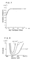
- the thus obtained product was subjected to a shearing test, the result of which is shown in Fig. 7.
- a high shearing strength of 150 N/mm2 can stably be obtained when the tightening torque is 200 N ⁇ cm or greater.
- an advantage the same as that provided by the preceding embodiment is obtained even when the bolts and nuts are of ordinary materials.
- Fig. 8 shows how the bonding strength is influenced by the bonding temperature and the pressing force. More specifically, the bonding strength is shown in terms of four-point flexural moment bending strength of a product which is composed of sialon member and a JIS S20C steel member bonded together with an Aluminium insert member. From this figure, it will be seen that the bonding temperature preferably ranges between 585°C and 630°C.
- the invention has been described with reference to the case where a ceramics material and a metallic member are bonded together as well as the case where different ceramics material are bonded, the invention can equally be applied to cases where bonding is to be conducted between members of the same ceramics material, members of the same metallic material, and members of different metallic materials.
- the use of the intermediate insert member is not essential.
- the method and device of the invention can be used when two members of, for example, copper are to be bonded directly or indirectly through the intermediary of silver plating layers on the joint surfaces of these copper members.
- the method and device of the present invention can also be used in bonding two members with a brazing material such as a copperbrazing material or a solder. It is also possible to use a sheet of titanium, copper and so forth as the insert member.
- the pressing force is controlled to be 1,5 N/mm2 or greater and the torque with which the nuts on the constraining bolts is controlled to be 100 N ⁇ cm or greater. Therefore, the members to be bonded are maintained in close contact with the insert member so as to eliminate generation of voids attributable to contamination of the surfaces of the members to be bonded and/or the insert member, whereby a sufficiently high bonding strength is stably obtained.
- the use of a simple jig makes it possible to employ a continuous heating furnace, thereby enabling products to be mass-produced at a moderate production cost.
Landscapes
- Engineering & Computer Science (AREA)
- Chemical & Material Sciences (AREA)
- Mechanical Engineering (AREA)
- Ceramic Engineering (AREA)
- Physics & Mathematics (AREA)
- Fluid Mechanics (AREA)
- Materials Engineering (AREA)
- Structural Engineering (AREA)
- Organic Chemistry (AREA)
- Pressure Welding/Diffusion-Bonding (AREA)
- Ceramic Products (AREA)
Applications Claiming Priority (2)
| Application Number | Priority Date | Filing Date | Title |
|---|---|---|---|
| JP4265987A JPS63210074A (ja) | 1987-02-27 | 1987-02-27 | 接合方法及び接合装置 |
| JP42659/87 | 1987-02-27 |
Publications (2)
| Publication Number | Publication Date |
|---|---|
| EP0280112A1 true EP0280112A1 (de) | 1988-08-31 |
| EP0280112B1 EP0280112B1 (de) | 1993-01-13 |
Family
ID=12642138
Family Applications (1)
| Application Number | Title | Priority Date | Filing Date |
|---|---|---|---|
| EP19880101895 Expired - Lifetime EP0280112B1 (de) | 1987-02-27 | 1988-02-09 | Verfahren und Vorrichtung zum Verbinden zweier oder mehrerer Teile |
Country Status (3)
| Country | Link |
|---|---|
| EP (1) | EP0280112B1 (de) |
| JP (1) | JPS63210074A (de) |
| DE (1) | DE3877376T2 (de) |
Cited By (4)
| Publication number | Priority date | Publication date | Assignee | Title |
|---|---|---|---|---|
| WO1989004069A1 (en) * | 1987-10-23 | 1989-05-05 | Chloride Silent Power Limited | Method of and apparatus for constructing an alkali metal energy conversion device |
| US6892781B2 (en) * | 2002-05-28 | 2005-05-17 | International Business Machines Corporation | Method and apparatus for application of pressure to a workpiece by thermal expansion |
| CN109396725A (zh) * | 2018-12-18 | 2019-03-01 | 中国电子科技集团公司第三十八研究所 | 一种用于大型液冷骨架结构件的扩散焊接工装 |
| EP4661119A1 (de) | 2024-06-06 | 2025-12-10 | Element 22 GmbH | Verfahren zur herstellung von geschichteten verbundwerkstoffpackungen zur verwendung als elektrode durch ein materialverbindungsverfahren |
Families Citing this family (1)
| Publication number | Priority date | Publication date | Assignee | Title |
|---|---|---|---|---|
| CN103056507B (zh) * | 2012-12-28 | 2015-04-15 | 哈尔滨工业大学 | 自蔓延连接专用的可连续调节压力的夹具 |
Citations (5)
| Publication number | Priority date | Publication date | Assignee | Title |
|---|---|---|---|---|
| US4252263A (en) * | 1980-04-11 | 1981-02-24 | General Electric Company | Method and apparatus for thermo-compression diffusion bonding |
| EP0090658A2 (de) * | 1982-03-31 | 1983-10-05 | De Beers Industrial Diamond Division (Proprietary) Limited | Schleifkörper |
| DE3233022A1 (de) * | 1982-09-06 | 1984-03-08 | BBC Aktiengesellschaft Brown, Boveri & Cie., 5401 Baden, Aargau | Verfahren zum direkten verbinden eines koerpers mit einem keramischen substrat |
| EP0123382A1 (de) * | 1983-03-15 | 1984-10-31 | The British Petroleum Company p.l.c. | Diffusionsverbindung von mit Gallium beschichteten Aluminium-Oberflächen |
| EP0135937A2 (de) * | 1983-09-28 | 1985-04-03 | Hitachi, Ltd. | Verfahren zum Verbinden von Aluminiumoxid mit Metall |
-
1987
- 1987-02-27 JP JP4265987A patent/JPS63210074A/ja active Pending
-
1988
- 1988-02-09 EP EP19880101895 patent/EP0280112B1/de not_active Expired - Lifetime
- 1988-02-09 DE DE19883877376 patent/DE3877376T2/de not_active Expired - Fee Related
Patent Citations (5)
| Publication number | Priority date | Publication date | Assignee | Title |
|---|---|---|---|---|
| US4252263A (en) * | 1980-04-11 | 1981-02-24 | General Electric Company | Method and apparatus for thermo-compression diffusion bonding |
| EP0090658A2 (de) * | 1982-03-31 | 1983-10-05 | De Beers Industrial Diamond Division (Proprietary) Limited | Schleifkörper |
| DE3233022A1 (de) * | 1982-09-06 | 1984-03-08 | BBC Aktiengesellschaft Brown, Boveri & Cie., 5401 Baden, Aargau | Verfahren zum direkten verbinden eines koerpers mit einem keramischen substrat |
| EP0123382A1 (de) * | 1983-03-15 | 1984-10-31 | The British Petroleum Company p.l.c. | Diffusionsverbindung von mit Gallium beschichteten Aluminium-Oberflächen |
| EP0135937A2 (de) * | 1983-09-28 | 1985-04-03 | Hitachi, Ltd. | Verfahren zum Verbinden von Aluminiumoxid mit Metall |
Non-Patent Citations (1)
| Title |
|---|
| CHEMICAL ABSTRACTS, vol. 103, no. 20, 18th November 1985, page 300, abstract no. 165153k, Columbus, Ohio, US; & JP-A-60 103 081 (HITACHI LTD) 07-06-1985 * |
Cited By (8)
| Publication number | Priority date | Publication date | Assignee | Title |
|---|---|---|---|---|
| WO1989004069A1 (en) * | 1987-10-23 | 1989-05-05 | Chloride Silent Power Limited | Method of and apparatus for constructing an alkali metal energy conversion device |
| GB2230378A (en) * | 1987-10-23 | 1990-10-17 | Chloride Silent Power Ltd | Method of and apparatus for constructing an alkali metal energy conversion device |
| GB2230378B (en) * | 1987-10-23 | 1991-03-27 | Chloride Silent Power Ltd | Apparatus for constructing an alkali metal energy conversion device |
| US5075957A (en) * | 1987-10-23 | 1991-12-31 | Chloride Silent Power, Limited | Apparatus for constructing an alkali metal energy conversion device |
| US6892781B2 (en) * | 2002-05-28 | 2005-05-17 | International Business Machines Corporation | Method and apparatus for application of pressure to a workpiece by thermal expansion |
| CN109396725A (zh) * | 2018-12-18 | 2019-03-01 | 中国电子科技集团公司第三十八研究所 | 一种用于大型液冷骨架结构件的扩散焊接工装 |
| EP4661119A1 (de) | 2024-06-06 | 2025-12-10 | Element 22 GmbH | Verfahren zur herstellung von geschichteten verbundwerkstoffpackungen zur verwendung als elektrode durch ein materialverbindungsverfahren |
| WO2025252384A1 (en) | 2024-06-06 | 2025-12-11 | Element 22 GmbH | A method of production of layered composite material packs for use as an electrode by a material bonding process |
Also Published As
| Publication number | Publication date |
|---|---|
| DE3877376T2 (de) | 1993-05-06 |
| EP0280112B1 (de) | 1993-01-13 |
| DE3877376D1 (de) | 1993-02-25 |
| JPS63210074A (ja) | 1988-08-31 |
Similar Documents
| Publication | Publication Date | Title |
|---|---|---|
| US4699310A (en) | Method of bonding alumina to metal | |
| US4942999A (en) | Metal-ceramic joined composite bodies and joining process therefor | |
| US4723862A (en) | Ceramic-metal joint structure | |
| JP2528718B2 (ja) | セラミックスと金属の接合方法 | |
| EP0280112A1 (de) | Verfahren und Vorrichtung zum Verbinden zweier oder mehrerer Teile | |
| EP0197397B1 (de) | Verfahren zum Verbinden von keramischen Bauteilen mit einem Metall | |
| US4749118A (en) | Method for bonding ceramic to metal | |
| Matsuoka | Ultrasonic welding of ceramic/metal | |
| JP3336485B2 (ja) | タペット | |
| JPH069907B2 (ja) | 黒鉛と金属からなる複合材の製造方法 | |
| JPS60186483A (ja) | 拡散接合方法 | |
| JPH0142914B2 (de) | ||
| JP2522125B2 (ja) | セラミックスと金属又はセラミックスとの接合方法 | |
| JPH1171186A (ja) | セラミックと金属との結合構造およびその結合方法 | |
| JPH0337165A (ja) | セラミックスと金属との接合方法 | |
| JP3365575B2 (ja) | セラミックスと金属の接合体 | |
| JPH0329029B2 (de) | ||
| JP2522124B2 (ja) | セラミックスとセラミックスとの接合方法 | |
| JPH0234908B2 (ja) | Hisankabutsuseramitsukusutokinzokunosetsugotai | |
| JPS61136969A (ja) | サイアロンと金属の接合方法 | |
| JPS62170336A (ja) | 黒鉛と金属からなる複合材 | |
| JPH03110083A (ja) | 繊維強化金属基複合材料の板材と金属板との接合方法 | |
| JPH06107472A (ja) | 窒化珪素系セラミックスと金属との接合方法 | |
| JPS61127675A (ja) | セラミツクスと金属との接合構造 | |
| JPH0366071B2 (de) |
Legal Events
| Date | Code | Title | Description |
|---|---|---|---|
| PUAI | Public reference made under article 153(3) epc to a published international application that has entered the european phase |
Free format text: ORIGINAL CODE: 0009012 |
|
| 17P | Request for examination filed |
Effective date: 19880209 |
|
| AK | Designated contracting states |
Kind code of ref document: A1 Designated state(s): DE FR GB |
|
| 17Q | First examination report despatched |
Effective date: 19900802 |
|
| GRAA | (expected) grant |
Free format text: ORIGINAL CODE: 0009210 |
|
| AK | Designated contracting states |
Kind code of ref document: B1 Designated state(s): DE FR GB |
|
| REF | Corresponds to: |
Ref document number: 3877376 Country of ref document: DE Date of ref document: 19930225 |
|
| ET | Fr: translation filed | ||
| PLBE | No opposition filed within time limit |
Free format text: ORIGINAL CODE: 0009261 |
|
| STAA | Information on the status of an ep patent application or granted ep patent |
Free format text: STATUS: NO OPPOSITION FILED WITHIN TIME LIMIT |
|
| 26N | No opposition filed | ||
| PGFP | Annual fee paid to national office [announced via postgrant information from national office to epo] |
Ref country code: FR Payment date: 19971216 Year of fee payment: 11 |
|
| PG25 | Lapsed in a contracting state [announced via postgrant information from national office to epo] |
Ref country code: FR Free format text: LAPSE BECAUSE OF NON-PAYMENT OF DUE FEES Effective date: 19991029 |
|
| REG | Reference to a national code |
Ref country code: FR Ref legal event code: ST |
|
| REG | Reference to a national code |
Ref country code: GB Ref legal event code: IF02 |
|
| PGFP | Annual fee paid to national office [announced via postgrant information from national office to epo] |
Ref country code: GB Payment date: 20020130 Year of fee payment: 15 |
|
| PGFP | Annual fee paid to national office [announced via postgrant information from national office to epo] |
Ref country code: DE Payment date: 20020425 Year of fee payment: 15 |
|
| PG25 | Lapsed in a contracting state [announced via postgrant information from national office to epo] |
Ref country code: GB Free format text: LAPSE BECAUSE OF NON-PAYMENT OF DUE FEES Effective date: 20030209 |
|
| PG25 | Lapsed in a contracting state [announced via postgrant information from national office to epo] |
Ref country code: DE Free format text: LAPSE BECAUSE OF NON-PAYMENT OF DUE FEES Effective date: 20030902 |
|
| GBPC | Gb: european patent ceased through non-payment of renewal fee |