EP0280193B1 - Construction du flanc de la dent d'un stator dans une machine électro-dynamique - Google Patents
Construction du flanc de la dent d'un stator dans une machine électro-dynamique Download PDFInfo
- Publication number
- EP0280193B1 EP0280193B1 EP88102368A EP88102368A EP0280193B1 EP 0280193 B1 EP0280193 B1 EP 0280193B1 EP 88102368 A EP88102368 A EP 88102368A EP 88102368 A EP88102368 A EP 88102368A EP 0280193 B1 EP0280193 B1 EP 0280193B1
- Authority
- EP
- European Patent Office
- Prior art keywords
- stator
- teeth
- lip
- slope angle
- degrees
- Prior art date
- Legal status (The legal status is an assumption and is not a legal conclusion. Google has not performed a legal analysis and makes no representation as to the accuracy of the status listed.)
- Revoked
Links
- 238000003475 lamination Methods 0.000 claims description 40
- 238000004804 winding Methods 0.000 claims description 40
- 239000003302 ferromagnetic material Substances 0.000 claims description 6
- 230000004907 flux Effects 0.000 claims description 4
- 230000005291 magnetic effect Effects 0.000 claims 1
- 239000004020 conductor Substances 0.000 description 8
- 238000010276 construction Methods 0.000 description 3
- 239000012212 insulator Substances 0.000 description 2
- 239000000463 material Substances 0.000 description 2
- 230000004323 axial length Effects 0.000 description 1
- 238000001816 cooling Methods 0.000 description 1
Images


Classifications
-
- H—ELECTRICITY
- H02—GENERATION; CONVERSION OR DISTRIBUTION OF ELECTRIC POWER
- H02K—DYNAMO-ELECTRIC MACHINES
- H02K1/00—Details of the magnetic circuit
- H02K1/06—Details of the magnetic circuit characterised by the shape, form or construction
- H02K1/12—Stationary parts of the magnetic circuit
-
- H—ELECTRICITY
- H02—GENERATION; CONVERSION OR DISTRIBUTION OF ELECTRIC POWER
- H02K—DYNAMO-ELECTRIC MACHINES
- H02K1/00—Details of the magnetic circuit
- H02K1/06—Details of the magnetic circuit characterised by the shape, form or construction
- H02K1/12—Stationary parts of the magnetic circuit
- H02K1/16—Stator cores with slots for windings
- H02K1/165—Shape, form or location of the slots
Definitions
- the present invention relates generally to stator constructions for dynamo-electric machines, and more particularly to a laminated stator comprised of a stack of plate laminations, wherein each of the laminations has a number of teeth extending radially from an inner bore opening, the teeth including lip parts to retain a stator winding with a closure wedge embedded in slots formed between adjacent teeth.
- Laminated stators for dynamo-electric machines are known generally from, for example, U.S. Patent 3,469,136 (September 23, 1969).
- the machine stator is comprised of a number of annular plate laminations of ferromagnetic material, stacked face-to-face with one another.
- Each plate has a circular inner opening to form a stator bore when the plates are stacked, and a number of equally circumferentially spaced slot openings extending radially from the circumference of the inner opening to form a number of teeth between which one or more stator windings are to be embedded.
- the winding slots in each plate together form a number of stator winding slots or recesses which extend generally parallel to the axis of the stator bore and a certain depth radially outward from the bore.
- One or more stator windings are then wound through selected ones of the slots between adjacent teeth, according to the number of poles desired for the machine.
- a slot insulator or liner Prior to inserting the winding conductors, a slot insulator or liner is usually inserted to extend axially along each slot in contact with the lamination material, to prevent arcing or short-circuiting between the winding conductors and the ferromagnetic material, of which the laminations are made.
- Each winding conductor is then inserted through mouth openings formed between adjacent teeth to enter the slot and, when all conductors of the winding or windings associated with the slot are in place, a closure wedge is inserted into the mouth slot, and lip parts of adjacent teeth which project into the mouth of the slot retain the wedge in place.
- U.S. Patent 4,486,506 December 4, 1984.
- An object of the invention is to ensure that the stator winding or windings are contained in the slot opening and to provide a lip structure which will minimize local flux saturation where a lip part is joined to a main body part of a stator tooth.
- a lamination for use in a laminated stator of a dynamo-electric machine includes a flat annular plate of ferromagnetic material with a generally circular inner opening to form a stator bore when like ones of the plate are stacked face to face.
- the plate has a number of uniformly circumferentially spaced slot openings extending from the circumference of the inner opening to form a number of teeth, the distal ends of which together define the circumference of the inner opening in the plate.
- Each of the teeth has a main body part and a pair of lip parts at its distal end, with each lip part projecting circumferentially into the mouth of a respective slot opening adjacent the tooth.
- Each lip part has an edge projecting from the main body part of the tooth to retain a stator winding and closure wedge when inserted in a slot opening adjacent the tooth, said edge being inclined to define a slope angle with respect to a line perpendicular to the center line of the slot opening into which the lip part projects.
- the slope angle for the lip parts is functionally related to the width of the teeth by varying in inverse relation of the width of the main body parts of said teeth.
- a dynamo-electric machine includes a generally cylindrical casing, a stator fixed in the casing and including a stack of plate laminations as claimed and having a cylindrical bore, a stator winding embedded in stator slots which extend radially outward from the circumference of the bore and generally parallel to the bore axis, a number of wedges each for containing the stator winding within the slots wherein the wedges are seated against lip parts of stator teeth adjacent the slots, and a rotor supported by the casing in the bore for rotational movement about the bore axis.
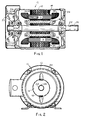
- Fig. 1 shows a side view, in section, of a dynamo electric machine 10, in which the present invention may be embodied.
- a front view of the machine 10 is shown in Fig. 2.
- the machine 10 includes a generally cylindrical outer casing 12, and a generally cylindrical stator 14 fixed coaxially within the outer casing 12 and having a coaxial stator bore 16.
- a rotor 18 is supported by suitable bearings 20a, 20b at the front and back of casing 12, to extend axially within the stator bore 16 and for rotational movement about the bore axis.
- a shaft part 22 of the rotor 18 extends axially from a front end shield 24 of the machine 10, and has a key 26 projecting radially outward from a recess cut axially a certain distance from the front of the shaft part 22. Key 26 serves to lock the shaft part 22 into a corresponding key way cut in a load member (not shown) e.g. a fan, to which rotational motive power is to be supplied by the machine 10.
- a load member not shown
- a back end shield 28 (Fig. 1) together with the casing 12 and the front end shield 24 serve to contain and protect the stator 14, rotor 18 and associated conductive windings.
- a machine cooling fan 30 is mounted on a rotor stub part 32 which extends outside the back end shield 28, and directs an air current flow over the casing.
- the stator 14 is comprised of a stack of plate laminations 34 of ferromagnetic material.
- the laminations 34 are stacked face-to-face and are suitably adhered to one another by means well known in the art. Slots which extend over the axial length of the stator 14 a certain radial depth from the stator bore 16, accommodate one or more stator windings, the end turns 36 of which are shown in Fig. 1. Details of the individual plate laminations 34 are given below in connection with Figs. 3 and 4.
- a plate lamination 34 in annular form includes an annular yoke portion 38 which extends from a circular outer periphery of the lamination 34 to a circumferential line 40 which defines the depths of a number of equally circumferentially spaced slot openings 42 from the circumference 44 of an inner opening in the lamination 34.
- the inner circumference 44 defines the diameter of the stator bore 16
- the individual slot openings 42 of the stacked laminations 34 are circumferentially aligned to form the axially extending slots within which the stator windings are embedded in the machine 10 of Fig. 1.
- the stator winding is inserted in the slot openings 42 through mouths 46 of the slot openings which mouths are wide enough to receive individual conductors of the stator winding.
- a number of teeth 48 are formed between adjacent slot openings 42, the teeth having main body parts 50 and lip parts 52 at distal ends of the teeth.
- Each lip part 52 projects circumferentially into the mouth 46 of a respective slot opening 42 adjacent the associated tooth 48.
- each lip part 52 has in inclined edge 54 projecting from the main body part 50 of an associated tooth.
- the edges 54 serve to retain a stator winding or windings and a closure wedge when the winding conductors are inserted in the slot opening 42 into which the edge 54 of the lip part 52 projects.
- Fig. 7 shows one example in which two stator windings 56, 58 are contained in each slot opening 42 by way of an insulated wedge 60 and an insulating winding separator 62.
- An insulative liner 64 is also placed within the slot opening 42 after the laminations 34 are stacked to define the winding slots in the machine stator 14 (Fig. 1).
- Each of the teeth 48 has a certain width T1 about a radial center line through its main body part 50, as shown in FIG. 4.
- the inclined edges 54 of the lip parts 52 define a slope angle ⁇ with respect to a line perpendicular to a center line of the slot opening 42 into which the lip part projects a distance P (see Fig. 4).
- the distance P is measured from the beginning of curvature point R to a line parallel to the slot center line, such line passing through the furthermost point M of the tooth tip toward the center line of the slot.
- the slope angle ⁇ for the lip part edges is functionally related to the width T1 of the teeth 48.
- the slope angle ⁇ varies in inverse relation to the width T1 of the main body parts 50 of the teeth 48 for a given circumferential opening for the mouths 46 of the opening 42.
- Such a relationship between the slope angle ⁇ and the teeth width T1 ensures that the stator winding or windings contained in the slot openings 42 and the closure wedge 60 will be firmly held in place by the lip parts 52 of adjacent teeth, while the machine 10 is operating. Specifically, it will be seen in Fig.
- a slope angle ⁇ in the range of from 15 degrees to 22 degrees provides superior seating reliability for stator winding wedges 60, particularly when the lip parts 52 project into the slot openings by only about 0.71 mm. as may occur if a width T1 of 6.9 mm. is chosen for the width of the teeth 48, as shown in Fig. 4.
- the slope angle ⁇ is preferably about 17.5 degrees.
- the slope angled ⁇ may then be selected to be greater than the 22.5 degree standard, so as to avoid saturation of the lamination material at the point where the edges 54 of the lip parts meet the main body parts 50 of the teeth 48.
- a plate lamination 34' with stator teeth 48' having lip parts 52' of such proportions is shown in Figs. 5 and 6.
- the width T1for the teeth 48' in the Figs. 5 and 6 embodiment is about 6.1 mm.
- the angle ⁇ for the lip parts 52' can be in the range of from 23 degrees to 30 degrees, preferably 27.5 degrees. Likewise such angles could be used for a lip width in the range of 1.1 mm. to 2.1 mm.
- This application 03 GP 6093 is being filed on the same day as commonly assigned applications 03 GP 6077 - BASE ASSEMBLY FOR DYNAMO-ELECTRIC MACHINE in the name of Robert L. Sieber, S. N. 019 823 ; 03 GP 6082 - DYNAMO-ELECTRIC MACHINE LAMINATION CONSTRUCTION in the name of Thomas W. Neumann, S. N. 020 297 ; and 03 GP 6073 - CLOSED SLOT ROTOR CONSTRUCTION in the names of Deepakkumar J. briefly et al., S. N. 020 299 . The entire disclosures of all of these three (3) other applications are specifically incorporated herein by reference.
Landscapes
- Engineering & Computer Science (AREA)
- Power Engineering (AREA)
- Iron Core Of Rotating Electric Machines (AREA)
- Insulation, Fastening Of Motor, Generator Windings (AREA)
Claims (12)
- Tôle destinée à être utilisée dans un empilage de tôles formant un stator dans une machine dynamo-électrique, comprenant :
une plaque annulaire plate en matériau ferro-magnétique comportant une périphérie extérieure sensiblement continue, et une ouverture intérieure circulaire dans son ensemble de manière à former un alésage dans le stator de la machine quand des plaques annulaires analogues parmi lesdites plaques annulaires sont empilées face contre face;
lesdites plaques comportant un grand nombre d'ouvertures formant encoches (42) espacées uniformément dans le sens circonférientiel et s'étendant radialement vers l'extérieur depuis la circonférence de ladite ouverture intérieure pour former un grand nombre de dents (48) de largeur prédéterminée, les entrées (46) desdites encoches (42) étant suffisamment larges pour recevoir un enroulement de stator quand cet enroulement est inséré entre lesdites dents et les extrémités distales desdites dents définissant ensemble la circonférence de ladite ouverture intérieure;
chacune desdites dents (48) comportant une partie corps principale (50) s'étendant radialement depuis son extrémité distale et une paire de parties lèvres (52) à l'extrémité distale, chaque lèvre (52) faisant saillie, dans le sens circonférentiel, dans l'entrée (46) d'une encoche correspondante (42) adjacente à la dent (48);
chaque lèvre (52) comportant un bord (54) faisant saillie de la partie corps principale (50) de la dent (48) pour retenir l'enroulement de stator quand celui-ci est inséré dans l'encoche (42) adjacente à la dent, ledit bord incliné (54) s'inclinant radialement vers l'intérieur de manière à définir un angle d'inclinaison (α) par rapport à une ligne perpendiculaire à l'axe de l'encoche (42) dans laquelle la lèvre (52) fait saillie,
caractérisée en ce que ledit angle d'inclinaison (α) varie en raison inverse de la largeur de la partie corps principale (50) desdites dents (48). - Tôle selon la revendication 1, dans laquelle ledit angle d'inclinaison (α) est compris entre 15° et 22°.
- Tôle selon la revendication 1, dans laquelle ledit angle d'inclinaison (α) est d'environ 17,5°.
- Tôle selon la revendication 1, dans laquelle chaque lèvre (52) fait saillie dans l'encoche correspondante (42) sur environ 0,71 mm et ledit angle d'inclinaison (α) est d'environ 17.5°.
- Tôle selon la revendication 2, dans laquelle chaque lèvre (52) fait saillie dans l'encoche correspondante (42) sur environ 0,71 mm, la largeur desdites dents (48) est d'environ 6,9 mm et ledit angle d'inclinaison (α) est d'environ 17,5°.
- Tôle selon la revendication 1, dans laquelle ledit angle d'inclinaison (α) est compris entre 23° et 30°.
- Tôle selon la revendication 1, dans laquelle ledit angle d'inclinaison (α) est d'environ 27,5°.
- Tôle selon [a revendication 1, dans laquelle chaque lèvre (52) fait saillie dans l'encoche correspondante sur environ 1,125 mm.
- Tôle selon la revendication 1, dans laquelle chaque lèvre (52) fait saillie dans l'encoche correspondante (42) sur environ 1,125 mm et la largeur desdites dents est d'environ 6,1 mm.
- Tôle selon la revendication 6, dans laquelle, pour une largeur donnée desdites dents (48), ledit angle d'inclinaison (α) est choisi de manière à minimiser la saturation du flux d'enroulement statorique aux points où les bords inclinés (54) des lèvres (52) coupent la partie de corps principale (50) de chaque dent (48).
- Tôle selon la revendication 1, dans laquelle la largeur de ladite lèvre (52) est comprise entre 1,1 mm et 2,1 mm et ledit angle d'inclinaison (α) est d'environ 27,5°.
- Tôle selon l'une quelconque des revendications 1 à 11, dans laquelle la machine dynamo-électrique comprend :
une carcasse (12) cylindrique d'une façon générale;
un stator (14) fixé dans ladite carcasse et constitué par un empilage desdites tôles (34) formant des plaques d'un matériau ferro-magnétique, ledit stator comportant un alésage cylindrique (16);
un enroulement de stator noyé dans les encoches de stator qui s'étendent radialement vers l'extérieur depuis la circonférence dudit alésage;
un grand nombre de clavettes (60), chacune servant à maintenir l'enroulement de stator a l'intérieur des encoches correspondantes desdites encoches, lesdites clavettes (60) prenant appui contre les lèvres (52) des dents (48) de stator adjacentes auxdites encoches, et
un rotor (18) supporté par ladite carcasse (12) dans ledit alésage (16) en vue d'un mouvement de rotation autour de l'axe de l'alésage, ledit rotor comprenant des moyens conducteurs pour une interaction avec un champ magnétique lorsque l'enroulement de stator est excité par une source électrique extérieure.
Applications Claiming Priority (2)
| Application Number | Priority Date | Filing Date | Title |
|---|---|---|---|
| US07/019,811 US4780636A (en) | 1987-02-27 | 1987-02-27 | Lip structure for a stator in a dynamo-electric machine |
| US19811 | 1998-02-06 |
Publications (3)
| Publication Number | Publication Date |
|---|---|
| EP0280193A2 EP0280193A2 (fr) | 1988-08-31 |
| EP0280193A3 EP0280193A3 (en) | 1990-01-10 |
| EP0280193B1 true EP0280193B1 (fr) | 1993-11-10 |
Family
ID=21795162
Family Applications (1)
| Application Number | Title | Priority Date | Filing Date |
|---|---|---|---|
| EP88102368A Revoked EP0280193B1 (fr) | 1987-02-27 | 1988-02-18 | Construction du flanc de la dent d'un stator dans une machine électro-dynamique |
Country Status (5)
| Country | Link |
|---|---|
| US (1) | US4780636A (fr) |
| EP (1) | EP0280193B1 (fr) |
| JP (1) | JPS6447240A (fr) |
| KR (1) | KR0135768B1 (fr) |
| DE (1) | DE3885477T2 (fr) |
Families Citing this family (14)
| Publication number | Priority date | Publication date | Assignee | Title |
|---|---|---|---|---|
| US5289065A (en) * | 1993-04-05 | 1994-02-22 | Ford Motor Company | Zero air gap orbiting gear stepper motor |
| GB2332048B (en) * | 1997-12-02 | 2002-06-26 | Louis J Bailey | Intergrated system for heating cooling and heat recovery ventilation |
| JP3535012B2 (ja) * | 1998-06-09 | 2004-06-07 | ミネベア株式会社 | ラジアルギャップ型小型円筒型回転電機 |
| JP3383251B2 (ja) * | 1999-12-27 | 2003-03-04 | 三菱電機株式会社 | 車両用交流発電機の固定子 |
| JP4476111B2 (ja) * | 2004-12-08 | 2010-06-09 | 三菱電機株式会社 | 交流発電機 |
| JP5130777B2 (ja) * | 2007-04-23 | 2013-01-30 | 株式会社豊田自動織機 | ステータ |
| JP5424814B2 (ja) * | 2009-05-21 | 2014-02-26 | 三菱電機株式会社 | 永久磁石型回転電機 |
| JP6156679B2 (ja) * | 2013-01-25 | 2017-07-05 | 株式会社デンソー | 回転電機の固定子 |
| CN103532267A (zh) * | 2013-10-09 | 2014-01-22 | 中达电机股份有限公司 | 2p电动机的定子冲片结构 |
| DE102016200081B4 (de) * | 2016-01-07 | 2025-08-07 | Schaeffler Technologies AG & Co. KG | Elektrische Maschine |
| KR20190068975A (ko) * | 2017-12-11 | 2019-06-19 | 현대자동차주식회사 | 구동모터 |
| JP7306040B2 (ja) * | 2019-04-19 | 2023-07-11 | ニデック株式会社 | モータ |
| KR20240127299A (ko) * | 2023-02-15 | 2024-08-22 | 보그워너 인코포레이티드 | 전기 기계 웨지 및 웨지의 삽입 방법 |
| JP7394501B1 (ja) * | 2023-06-26 | 2023-12-08 | E-Tec株式会社 | 固定子、固定子製造方法および固定子製造装置 |
Family Cites Families (19)
| Publication number | Priority date | Publication date | Assignee | Title |
|---|---|---|---|---|
| US2610225A (en) * | 1948-12-20 | 1952-09-09 | Emerson Electric Mfg Co | Core construction for electrical equipment |
| US2700115A (en) * | 1950-10-10 | 1955-01-18 | Walt Inc De | Air-cooled electric motor |
| CH313455A (fr) * | 1952-11-13 | 1956-04-15 | Cem Comp Electro Mec | Ensemble de faux rotors pour machines à bobiner les stators de machines électriques |
| US2701317A (en) * | 1953-11-18 | 1955-02-01 | Gen Electric | Dynamoelectric machine winding insulator |
| FR1169617A (fr) * | 1955-12-30 | 1958-12-31 | Gen Motors Corp | Isolation pour moteur, notamment pour moteur de réfrigérateur |
| US3253171A (en) * | 1961-11-30 | 1966-05-24 | Smith Corp A O | Laminated structure binding means |
| US3229134A (en) * | 1962-01-25 | 1966-01-11 | Litton Industries Inc | Thermal variation compensation means and method |
| US3235762A (en) * | 1962-05-02 | 1966-02-15 | Gen Electric | Stator for use in alternating current induction motors |
| US3469136A (en) * | 1968-03-21 | 1969-09-23 | Lucas Industries Ltd | Laminated stators for dynamo electric machines |
| US3735169A (en) * | 1971-04-04 | 1973-05-22 | Gen Electric | Channel,shaped,laminated,high temperature slot wedge for dynamoelectric machines |
| JPS5341321B1 (fr) * | 1971-07-30 | 1978-11-02 | ||
| US3827141A (en) * | 1972-05-17 | 1974-08-06 | Skf Ind Trading & Dev | Method of manufacturing an electric rotary machine |
| US3821846A (en) * | 1973-01-10 | 1974-07-02 | Smith Corp A | Method of manufacturing a motor stator assembly |
| US3909648A (en) * | 1973-07-27 | 1975-09-30 | Smith Corp A O | Electric motor having a winding insulating barrier and method of construction |
| US4241274A (en) * | 1978-05-10 | 1980-12-23 | General Electric Company | Dynamoelectric machine and stationary assembly therefor |
| FR2481017A1 (fr) * | 1980-04-17 | 1981-10-23 | Ducellier & Cie | Machine electrique notamment alternateur pour vehicule automobile |
| JPS57101540A (en) * | 1980-12-11 | 1982-06-24 | Fanuc Ltd | Induction motor |
| US4486506A (en) * | 1981-10-16 | 1984-12-04 | Tokyo Shibaura Denki Kabushiki Kaisha | Solid insulator and electric equipment coil using the same |
| US4654552A (en) * | 1985-03-28 | 1987-03-31 | General Electric Company | Lanced strip and edgewise wound core |
-
1987
- 1987-02-27 US US07/019,811 patent/US4780636A/en not_active Expired - Lifetime
-
1988
- 1988-02-18 EP EP88102368A patent/EP0280193B1/fr not_active Revoked
- 1988-02-18 DE DE3885477T patent/DE3885477T2/de not_active Revoked
- 1988-02-26 JP JP63042413A patent/JPS6447240A/ja active Pending
- 1988-02-27 KR KR1019880002025A patent/KR0135768B1/ko not_active Expired - Lifetime
Also Published As
| Publication number | Publication date |
|---|---|
| US4780636A (en) | 1988-10-25 |
| DE3885477T2 (de) | 1994-06-16 |
| KR0135768B1 (ko) | 1998-04-23 |
| DE3885477D1 (de) | 1993-12-16 |
| JPS6447240A (en) | 1989-02-21 |
| KR880010535A (ko) | 1988-10-10 |
| EP0280193A2 (fr) | 1988-08-31 |
| EP0280193A3 (en) | 1990-01-10 |
Similar Documents
| Publication | Publication Date | Title |
|---|---|---|
| EP0280193B1 (fr) | Construction du flanc de la dent d'un stator dans une machine électro-dynamique | |
| EP0280194B1 (fr) | Construction de tôle pour machine électro-dynamique | |
| US6703741B1 (en) | Permanent magnet rotor portion for electric machines | |
| EP0740397B1 (fr) | Structure pour un stator de machine électrique tournante | |
| EP0314860A1 (fr) | Construction d'un paquet de tôles de stator et de rotor pour une machine dynamo-électrique | |
| CN102132472B (zh) | 电机 | |
| JPH08251891A (ja) | ハイブリッド励磁式回転電機 | |
| JPH0132743B2 (fr) | ||
| EP0429729A1 (fr) | Machines électriques à induit discoide comportant un noyau en fer | |
| JP2003510998A (ja) | 電気的機械用永久磁石ロータ | |
| EP0136584B1 (fr) | Rotor pour machine tournante | |
| JP2019509709A (ja) | 半埋め込み型磁石および軸方向保持手段を有する軸方向磁束電磁モータまたは発電機用のロータ | |
| JP2003134762A (ja) | 回転電機 | |
| JPH08251848A (ja) | 永久磁石形同期回転電機のロータ | |
| EP1354394A1 (fr) | Degagement dans zone d'encoche pour stators a segments | |
| JP2002064951A (ja) | 永久磁石埋め込み型ロータ | |
| US3427486A (en) | Dynamoelectric machines using ceramic permanent magnets | |
| EP0352573A1 (fr) | Lamelle de tôle rotorique d'une machine synchrone | |
| US2560560A (en) | Stator for universal electric motors | |
| JPH08107639A (ja) | 永久磁石形同期回転電機のロータ | |
| US6252330B1 (en) | Dynamo-electric rotor with reduced magnetic flux leakage and with a structure permitting high efficiency assembly | |
| JP2960128B2 (ja) | レラクタンス回転機 | |
| JPS6268051A (ja) | 永久磁石界磁型電動機 | |
| EP0157526A2 (fr) | Machine rotative à réluctance | |
| JPS61293142A (ja) | 径方向に垂直な方向に磁場をつくる永久磁石からなる回転子を備える高速同期回転機 |
Legal Events
| Date | Code | Title | Description |
|---|---|---|---|
| PUAI | Public reference made under article 153(3) epc to a published international application that has entered the european phase |
Free format text: ORIGINAL CODE: 0009012 |
|
| AK | Designated contracting states |
Kind code of ref document: A2 Designated state(s): DE FR GB IT NL SE |
|
| PUAL | Search report despatched |
Free format text: ORIGINAL CODE: 0009013 |
|
| AK | Designated contracting states |
Kind code of ref document: A3 Designated state(s): DE FR GB IT NL SE |
|
| 17P | Request for examination filed |
Effective date: 19900627 |
|
| 17Q | First examination report despatched |
Effective date: 19920527 |
|
| GRAA | (expected) grant |
Free format text: ORIGINAL CODE: 0009210 |
|
| AK | Designated contracting states |
Kind code of ref document: B1 Designated state(s): DE FR GB IT NL SE |
|
| REF | Corresponds to: |
Ref document number: 3885477 Country of ref document: DE Date of ref document: 19931216 |
|
| ET | Fr: translation filed | ||
| ITF | It: translation for a ep patent filed | ||
| PLBI | Opposition filed |
Free format text: ORIGINAL CODE: 0009260 |
|
| 26 | Opposition filed |
Opponent name: DANFOSS A/S Effective date: 19940808 |
|
| NLR1 | Nl: opposition has been filed with the epo |
Opponent name: DANFOSS A/S |
|
| EAL | Se: european patent in force in sweden |
Ref document number: 88102368.3 |
|
| PLBF | Reply of patent proprietor to notice(s) of opposition |
Free format text: ORIGINAL CODE: EPIDOS OBSO |
|
| PGFP | Annual fee paid to national office [announced via postgrant information from national office to epo] |
Ref country code: FR Payment date: 19970115 Year of fee payment: 10 |
|
| PGFP | Annual fee paid to national office [announced via postgrant information from national office to epo] |
Ref country code: DE Payment date: 19970117 Year of fee payment: 10 |
|
| PGFP | Annual fee paid to national office [announced via postgrant information from national office to epo] |
Ref country code: GB Payment date: 19970127 Year of fee payment: 10 |
|
| RDAH | Patent revoked |
Free format text: ORIGINAL CODE: EPIDOS REVO |
|
| APAC | Appeal dossier modified |
Free format text: ORIGINAL CODE: EPIDOS NOAPO |
|
| APAE | Appeal reference modified |
Free format text: ORIGINAL CODE: EPIDOS REFNO |
|
| APAB | Appeal dossier modified |
Free format text: ORIGINAL CODE: EPIDOS NOAPE |
|
| APAC | Appeal dossier modified |
Free format text: ORIGINAL CODE: EPIDOS NOAPO |
|
| RDAG | Patent revoked |
Free format text: ORIGINAL CODE: 0009271 |
|
| STAA | Information on the status of an ep patent application or granted ep patent |
Free format text: STATUS: PATENT REVOKED |
|
| PGFP | Annual fee paid to national office [announced via postgrant information from national office to epo] |
Ref country code: SE Payment date: 19980120 Year of fee payment: 11 |
|
| PGFP | Annual fee paid to national office [announced via postgrant information from national office to epo] |
Ref country code: NL Payment date: 19980121 Year of fee payment: 11 |
|
| 27W | Patent revoked |
Effective date: 19971207 |
|
| GBPR | Gb: patent revoked under art. 102 of the ep convention designating the uk as contracting state |
Free format text: 971207 |
|
| NLR2 | Nl: decision of opposition | ||
| APAH | Appeal reference modified |
Free format text: ORIGINAL CODE: EPIDOSCREFNO |