EP0280203A2 - Procédé et appareil pour la fabrication de corps creux en matière thermoplastique orientée - Google Patents
Procédé et appareil pour la fabrication de corps creux en matière thermoplastique orientée Download PDFInfo
- Publication number
- EP0280203A2 EP0280203A2 EP88102413A EP88102413A EP0280203A2 EP 0280203 A2 EP0280203 A2 EP 0280203A2 EP 88102413 A EP88102413 A EP 88102413A EP 88102413 A EP88102413 A EP 88102413A EP 0280203 A2 EP0280203 A2 EP 0280203A2
- Authority
- EP
- European Patent Office
- Prior art keywords
- molding
- mandrel
- wall
- tempering
- molded article
- Prior art date
- Legal status (The legal status is an assumption and is not a legal conclusion. Google has not performed a legal analysis and makes no representation as to the accuracy of the status listed.)
- Granted
Links
Images


Classifications
-
- B—PERFORMING OPERATIONS; TRANSPORTING
- B29—WORKING OF PLASTICS; WORKING OF SUBSTANCES IN A PLASTIC STATE IN GENERAL
- B29C—SHAPING OR JOINING OF PLASTICS; SHAPING OF MATERIAL IN A PLASTIC STATE, NOT OTHERWISE PROVIDED FOR; AFTER-TREATMENT OF THE SHAPED PRODUCTS, e.g. REPAIRING
- B29C31/00—Handling, e.g. feeding of the material to be shaped, storage of plastics material before moulding; Automation, i.e. automated handling lines in plastics processing plants, e.g. using manipulators or robots
- B29C31/002—Handling tubes, e.g. transferring between shaping stations, loading on mandrels
-
- B—PERFORMING OPERATIONS; TRANSPORTING
- B29—WORKING OF PLASTICS; WORKING OF SUBSTANCES IN A PLASTIC STATE IN GENERAL
- B29C—SHAPING OR JOINING OF PLASTICS; SHAPING OF MATERIAL IN A PLASTIC STATE, NOT OTHERWISE PROVIDED FOR; AFTER-TREATMENT OF THE SHAPED PRODUCTS, e.g. REPAIRING
- B29C49/00—Blow-moulding, i.e. blowing a preform or parison to a desired shape within a mould; Apparatus therefor
- B29C49/42—Component parts, details or accessories; Auxiliary operations
- B29C49/64—Heating or cooling preforms, parisons or blown articles
-
- B—PERFORMING OPERATIONS; TRANSPORTING
- B29—WORKING OF PLASTICS; WORKING OF SUBSTANCES IN A PLASTIC STATE IN GENERAL
- B29C—SHAPING OR JOINING OF PLASTICS; SHAPING OF MATERIAL IN A PLASTIC STATE, NOT OTHERWISE PROVIDED FOR; AFTER-TREATMENT OF THE SHAPED PRODUCTS, e.g. REPAIRING
- B29C55/00—Shaping by stretching, e.g. drawing through a die; Apparatus therefor
- B29C55/22—Shaping by stretching, e.g. drawing through a die; Apparatus therefor of tubes
- B29C55/24—Shaping by stretching, e.g. drawing through a die; Apparatus therefor of tubes radial
-
- B—PERFORMING OPERATIONS; TRANSPORTING
- B29—WORKING OF PLASTICS; WORKING OF SUBSTANCES IN A PLASTIC STATE IN GENERAL
- B29C—SHAPING OR JOINING OF PLASTICS; SHAPING OF MATERIAL IN A PLASTIC STATE, NOT OTHERWISE PROVIDED FOR; AFTER-TREATMENT OF THE SHAPED PRODUCTS, e.g. REPAIRING
- B29C57/00—Shaping of tube ends, e.g. flanging, belling or closing; Apparatus therefor, e.g. collapsible mandrels
-
- B—PERFORMING OPERATIONS; TRANSPORTING
- B29—WORKING OF PLASTICS; WORKING OF SUBSTANCES IN A PLASTIC STATE IN GENERAL
- B29K—INDEXING SCHEME ASSOCIATED WITH SUBCLASSES B29B, B29C OR B29D, RELATING TO MOULDING MATERIALS OR TO MATERIALS FOR MOULDS, REINFORCEMENTS, FILLERS OR PREFORMED PARTS, e.g. INSERTS
- B29K2995/00—Properties of moulding materials, reinforcements, fillers, preformed parts or moulds
- B29K2995/0037—Other properties
- B29K2995/005—Oriented
-
- B—PERFORMING OPERATIONS; TRANSPORTING
- B29—WORKING OF PLASTICS; WORKING OF SUBSTANCES IN A PLASTIC STATE IN GENERAL
- B29L—INDEXING SCHEME ASSOCIATED WITH SUBCLASS B29C, RELATING TO PARTICULAR ARTICLES
- B29L2031/00—Other particular articles
- B29L2031/712—Containers; Packaging elements or accessories, Packages
- B29L2031/7132—Bowls, Cups, Glasses
Definitions
- This process can, for example, be such that an intermediate product is produced by stretching the wall of a molding at a temperature below the glass transition temperature of the material forming it, which intermediate product is expanded at least over most of its longitudinal extent and then heat-set.
- thermostability of the hollow body to be produced which is aimed at by the temperature control process, it is necessary that the required heating of the molded article takes place as uniformly as possible in order to avoid the presence of areas of different thermostability in the hollow body to be manufactured.
- the temperature required for heating the mandrel to the temperature required for heat setting should be carried out as quickly as possible.
- the tempering mandrel with an outer diameter which is noticeably larger than the inner diameter of the non-pre-expanded wall area of the molding, so that at least the non-pre-expanded area of the molding for orientation in the circumferential direction of the thermoplastic which forms it Material experiences a noticeable increase in cross-section.
- the tempering mandrel is also used to carry out such a large diameter enlargement of the molding that this diameter enlargement also results in an orientation of the material forming the molding wall essentially depends, as has already been explained, on the manufacturing steps of the molding until Has undergone the tempering process or the pre-expansion preceding this. If the material forming the wall of the molded article has already been oriented in the circumferential direction during these preceding treatment steps, there is generally no need for the diameter to be increased by the temperature mandrel for the purpose of orienting the plastic material.
- the cooling sleeve is then moved into a position remote from the molded article, so that it releases the molded article and this is gripped by a holder which engages on the outside thereof, whereupon the base mandrel is moved back from the molded article and the holding mandrel is also pulled out of the molded article .
- the tempering mandrel can also be moved away from the molding by the distance that is necessary in order to disengage from the molding.
- the device used to carry out the above-described method is provided with a heatable mandrel, which tapers conically towards its free end, for pre-expanding the end region of the molding, the smallest cross section of which is smaller than the cross section of the end region of the molding in not pre-expanded expanded state, and the largest diameter of which is greater than the cross section of the end region to be pre-expanded, the portion of the mandrel which acts to pre-expand being delimited by a surface which is linear or concave in longitudinal section.
- the latter feature takes into account the fact that the blank to be pre-expanded by the conical mandrel will generally be very thin-walled.
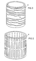
- each molding 10 consists essentially of an inwardly drawn, dome-shaped base 12 and a cylindrical wall 14, the upper, free end of which defines an opening. It can have been produced as an intermediate product from a preform using a drawing process, as described for example in FR-OS 25 67 066/8510215. After this drawing process, the wall of the molded article 10 has a thickness of, for example, 0.1 to 0.3 mm.
- the bottom 12 of the molding is noticeably thicker because it has not been influenced by the drawing process restricted to the wall 14.
- the drawing process is generally carried out at a temperature of the preform or the wall thereof which is below the glass transition temperature of the thermoplastic material.
- the wall 14 of a molding 10 produced in the manner described above is oriented in the axial direction by the drawing process.
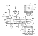
- a cam drum 19 is arranged coaxially within the housing 18, which rotates about its longitudinal axis and bears several curves 22 on the outside. The latter cooperate with cam rollers 25 which are connected to the treatment agent.
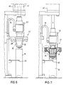
- the concave region 38 then comes into contact with the upper end region 23 of the molding. Since the mandrel 32 through the elec trical resistor 35 is heated to a temperature suitable for softening the thermoplastic material, the thermoplastic material will also experience a corresponding heating as soon as it comes into contact with the mandrel 32. This leads to a softening of the material in the end region 23, which in this state can be deformed using relatively low forces.
- the mandrel 32 is carried by a piston 41 which is guided within a pneumatic cylinder 42 and is acted upon in the direction of the blank 10 (Fig. 6).
- the lower group 47 of treatment agents has a base mandrel 50, a support sleeve 51 surrounding the latter, a cooling sleeve 52 surrounding the latter, and a movable clamping ring 53 surrounding the cooling sleeve 52. All of these parts are independently axially slidably mounted.
- the remaining parts of the lower group 47 that is to say the support sleeve 51, the cooling sleeve 52 and the movable clamping ring 53, also take part in the upward movement of the base mandrel 50 until it rests on the base 12 of the molding 10, so that these means as a unit from the position according to 10 into which FIG. 11 can be moved, although each of these means is assigned its own drive in the form of a cam roller.
- the support sleeve 51 is shifted upward, the inside diameter of which is the outside diameter of the molded article 10 does not correspond to pre-expanded area.
- the upper end position of the support sleeve 51 is shown in Fig. 12. It is located a short distance from the lower end of the tempering mandrel 56, which still occupies its upper starting position in FIG. 12, the free end of which protrudes into the pre-widened end region of the molded article 10 after it has been raised by the above-mentioned common upward movement of the bottom mandrel 50 and the holding mandrel 55 had been moved up to a position.
- FIG 14 shows the position of the temperature control mandrel 56 after the expansion process has ended.
- the temperature control mandrel 56 remains in this position for a period of time which is required for the desired heat setting.
- holding mandrel 55 and bottom mandrel 50 are brought back into contact with the bottom 12 of the expanded molding.
- the movable clamping ring 53 is displaced by a short distance, so that the edge of the molding is released.
- the cooling sleeve 51 and the lower clamping ring 53 are also moved downwards so far that they release the molded article.
- the gripper 75 can then be closed around the molding.
- the base mandrel 50 and holding mandrel 55 are then moved away from the molding or out of the molding pulled out so that it can be transported by the gripper 75 by a pivoting movement of the transport device 72 out of the treatment station 28 and to the transport shaft 30.
- the cam drum 19 is driven by a motor 82, on whose shaft, possibly with the interposition of a gear, sits a gear 83 which meshes with a ring gear 84 which is attached to an inwardly projecting flange of the cam drum 19.
Landscapes
- Engineering & Computer Science (AREA)
- Mechanical Engineering (AREA)
- Physics & Mathematics (AREA)
- Thermal Sciences (AREA)
- Manufacturing & Machinery (AREA)
- Robotics (AREA)
- Blow-Moulding Or Thermoforming Of Plastics Or The Like (AREA)
- Shaping By String And By Release Of Stress In Plastics And The Like (AREA)
- Shaping Of Tube Ends By Bending Or Straightening (AREA)
Applications Claiming Priority (2)
| Application Number | Priority Date | Filing Date | Title |
|---|---|---|---|
| DE3705947 | 1987-02-25 | ||
| DE19873705947 DE3705947A1 (de) | 1987-02-25 | 1987-02-25 | Verfahren und vorrichtung zum herstellen von hohlkoerpern aus orientiertem thermoplastischem kunststoff |
Publications (3)
| Publication Number | Publication Date |
|---|---|
| EP0280203A2 true EP0280203A2 (fr) | 1988-08-31 |
| EP0280203A3 EP0280203A3 (fr) | 1991-05-02 |
| EP0280203B1 EP0280203B1 (fr) | 1994-08-03 |
Family
ID=6321684
Family Applications (1)
| Application Number | Title | Priority Date | Filing Date |
|---|---|---|---|
| EP88102413A Expired - Lifetime EP0280203B1 (fr) | 1987-02-25 | 1988-02-19 | Procédé et appareil pour la fabrication de corps creux en matière thermoplastique orientée |
Country Status (4)
| Country | Link |
|---|---|
| US (1) | US4894198A (fr) |
| EP (1) | EP0280203B1 (fr) |
| JP (1) | JP2623107B2 (fr) |
| DE (2) | DE3705947A1 (fr) |
Cited By (1)
| Publication number | Priority date | Publication date | Assignee | Title |
|---|---|---|---|---|
| WO1990005625A1 (fr) * | 1988-11-14 | 1990-05-31 | Plm Ab | Procede et dispositif pour regler la temperature d'un preforme |
Families Citing this family (8)
| Publication number | Priority date | Publication date | Assignee | Title |
|---|---|---|---|---|
| SE450630B (sv) * | 1984-12-14 | 1987-07-13 | Petainer Sa | Sett och anordning for tillverkning av en plastbehallare genom omformning av en i huvudsak rorliknande forform |
| GB8827967D0 (en) * | 1988-11-30 | 1989-01-05 | Ward I M | Die-free drawing |
| US5445783A (en) * | 1993-07-06 | 1995-08-29 | Ford Motor Company | Blow molding method |
| US20050269744A1 (en) * | 2004-06-07 | 2005-12-08 | Lonsway Michael J | Stretched container and method of manufacture |
| US20080054525A1 (en) * | 2006-09-06 | 2008-03-06 | Graham Packaging Company, Lp | Method and apparatus for stretching the neck finish of a molded plastic article |
| DE102013010693B4 (de) * | 2013-06-27 | 2015-11-19 | Khs Corpoplast Gmbh | Vorrichtung zum Erwärmen von Vorformlingen aus thermoplastischem Kunststoff |
| CN104802390B (zh) * | 2015-04-17 | 2017-03-01 | 江苏新美星包装机械股份有限公司 | 一种瓶坯分流装置 |
| CN110039758B (zh) * | 2019-05-23 | 2023-12-26 | 江苏鼎尚电子材料股份有限公司 | 热缩管生产补气机构 |
Family Cites Families (7)
| Publication number | Priority date | Publication date | Assignee | Title |
|---|---|---|---|---|
| FR437036A (fr) * | 1911-11-22 | 1912-04-11 | John Christopher Taliaferro | Machine automatique à faire les rebords de boites de conserves |
| US3812696A (en) * | 1970-10-22 | 1974-05-28 | Crown Cork & Seal Co | Method of and apparatus for forming container bodies |
| US4412966A (en) * | 1979-11-07 | 1983-11-01 | Yoshino Kogyosho Co., Ltd. | Neck orienting method of bottles of saturated polyester resins |
| DE3101283C2 (de) * | 1981-01-16 | 1986-01-16 | Krupp Corpoplast Maschinenbau GmbH, 2000 Hamburg | Vorrichtung zum Herstellen von aus thermoplastischem Kunststoff bestehenden Vorformlingen für das Blasformen von Hohlkörpern |
| SE428775B (sv) * | 1981-11-26 | 1983-07-25 | Plm Ab | Behallare samt sett och anordning for att framstella en sadan |
| SE451969B (sv) * | 1984-07-05 | 1987-11-09 | Petainer Sa | Sett att framstella en behallare fran ett rorformat och i botten tillslutet emne av orienterbart plastmaterial |
| SE450630B (sv) * | 1984-12-14 | 1987-07-13 | Petainer Sa | Sett och anordning for tillverkning av en plastbehallare genom omformning av en i huvudsak rorliknande forform |
-
1987
- 1987-02-25 DE DE19873705947 patent/DE3705947A1/de not_active Withdrawn
- 1987-12-04 US US07/129,025 patent/US4894198A/en not_active Expired - Fee Related
-
1988
- 1988-02-19 DE DE3850892T patent/DE3850892D1/de not_active Expired - Fee Related
- 1988-02-19 EP EP88102413A patent/EP0280203B1/fr not_active Expired - Lifetime
- 1988-02-25 JP JP63040911A patent/JP2623107B2/ja not_active Expired - Lifetime
Cited By (3)
| Publication number | Priority date | Publication date | Assignee | Title |
|---|---|---|---|---|
| WO1990005625A1 (fr) * | 1988-11-14 | 1990-05-31 | Plm Ab | Procede et dispositif pour regler la temperature d'un preforme |
| US5145629A (en) * | 1988-11-14 | 1992-09-08 | Plm Ab | Process and apparatus for temperature conditioning a thermoplastic blank |
| US5340526A (en) * | 1988-11-14 | 1994-08-23 | Plm Ab | Temperature conditioning |
Also Published As
| Publication number | Publication date |
|---|---|
| DE3850892D1 (de) | 1994-09-08 |
| DE3705947A1 (de) | 1988-09-08 |
| JPS63227318A (ja) | 1988-09-21 |
| JP2623107B2 (ja) | 1997-06-25 |
| US4894198A (en) | 1990-01-16 |
| EP0280203A3 (fr) | 1991-05-02 |
| EP0280203B1 (fr) | 1994-08-03 |
Similar Documents
| Publication | Publication Date | Title |
|---|---|---|
| EP0387737B1 (fr) | Procédé pour réchauffer des préformes injectées prélevées d'une réserve, pour les souffler enfin dans un moule de soufflage et en faire des corps creux et procédé pour le moulage par soufflage de préformes préfabriquées | |
| DE69204350T2 (de) | Injections- und Streckblasverfahren zum Formen von Hohlkörpern mit dickem Boden. | |
| DE3314106C2 (de) | Vorrichtung zum Herstellen von Hohlkörpern aus warmformbarem Kunststoff | |
| EP2428347B1 (fr) | Dispositif et procédé destinés à la fabrication de récipients ovales en matière plastique | |
| DE3587856T2 (de) | Hohlkörper und Verfahren und Vorrichtung zu dessen Herstellung. | |
| DE2161066B2 (de) | Verfahren und vorrichtung zur herstellung eines hohlkoerpers aus thermoplastischem kunststoff | |
| DE69328561T2 (de) | Blasformling, verfahren und vorrichtung | |
| DE2856132A1 (de) | Vorrichtung zur herstellung von biaxial orientierten spritzgussteilen | |
| DE3006064A1 (de) | Verfahren und vorrichtung zur herstellung von kunststoff-flaschen | |
| EP0280204B1 (fr) | Procédé et appareil pour le formage d'un flanc à un corps creux en matière thermoplastique | |
| DE3020913A1 (de) | Verfahren zur herstellung eines rohlings fuer einen behaelter und gem. dem verfahren hergestellter rohling | |
| DE69523249T2 (de) | Verfahren zum Blasformen von grossen Behältern durch Streckblasformen | |
| EP0280203B1 (fr) | Procédé et appareil pour la fabrication de corps creux en matière thermoplastique orientée | |
| EP0062144A2 (fr) | Procédé et appareil pour calibrer des corps creux en matière thermoplastique orientés biaxialement | |
| DE2611244A1 (de) | Verfahren und vorrichtung zum zweistufigen blasformen | |
| DE2807199A1 (de) | Verfahren und vorrichtung zur herstellung von hohlkoerpern aus thermoplastischem kunststoff | |
| DE69024371T2 (de) | Verfahren und vorrichtung zum herstellen eines behälters | |
| EP3103616A1 (fr) | Dispositif et procédé destinés à la fabrication de récipients en matière plastique ovales | |
| EP1619006A2 (fr) | Procédé et appareil pour la fabrication d'un corps creux avec au moins un insert | |
| DE68906785T2 (de) | Verfahren und vorrichtung zur temperaturregelung eines vorformlings. | |
| DE1704119B1 (de) | Verfahren und maschine zum herstellen von hohlkoerpern insbesondere flaschen aus thermoplastischem kunststoff | |
| WO1998021019A1 (fr) | Procede et dispositif de transfert de pieces moulees | |
| DE29713665U1 (de) | Vorrichtung zum thermischen Formen von Kunststoffolien | |
| DE69123154T2 (de) | Verfahren und vorrichtung zum herstellen eines behälters | |
| EP0234300B1 (fr) | Procédé et dispositif de fabrication de corps creux en matière thermoplastique |
Legal Events
| Date | Code | Title | Description |
|---|---|---|---|
| PUAI | Public reference made under article 153(3) epc to a published international application that has entered the european phase |
Free format text: ORIGINAL CODE: 0009012 |
|
| AK | Designated contracting states |
Kind code of ref document: A2 Designated state(s): DE FR GB IT |
|
| PUAL | Search report despatched |
Free format text: ORIGINAL CODE: 0009013 |
|
| AK | Designated contracting states |
Kind code of ref document: A3 Designated state(s): DE FR GB IT |
|
| 17P | Request for examination filed |
Effective date: 19910827 |
|
| 17Q | First examination report despatched |
Effective date: 19921203 |
|
| GRAA | (expected) grant |
Free format text: ORIGINAL CODE: 0009210 |
|
| AK | Designated contracting states |
Kind code of ref document: B1 Designated state(s): DE FR GB IT |
|
| REF | Corresponds to: |
Ref document number: 3850892 Country of ref document: DE Date of ref document: 19940908 |
|
| GBT | Gb: translation of ep patent filed (gb section 77(6)(a)/1977) |
Effective date: 19940916 |
|
| ITF | It: translation for a ep patent filed | ||
| ET | Fr: translation filed | ||
| PLBE | No opposition filed within time limit |
Free format text: ORIGINAL CODE: 0009261 |
|
| STAA | Information on the status of an ep patent application or granted ep patent |
Free format text: STATUS: NO OPPOSITION FILED WITHIN TIME LIMIT |
|
| 26N | No opposition filed | ||
| PGFP | Annual fee paid to national office [announced via postgrant information from national office to epo] |
Ref country code: DE Payment date: 19990109 Year of fee payment: 12 |
|
| PGFP | Annual fee paid to national office [announced via postgrant information from national office to epo] |
Ref country code: GB Payment date: 19990211 Year of fee payment: 12 |
|
| PGFP | Annual fee paid to national office [announced via postgrant information from national office to epo] |
Ref country code: FR Payment date: 19990224 Year of fee payment: 12 |
|
| PG25 | Lapsed in a contracting state [announced via postgrant information from national office to epo] |
Ref country code: GB Free format text: LAPSE BECAUSE OF NON-PAYMENT OF DUE FEES Effective date: 20000219 |
|
| GBPC | Gb: european patent ceased through non-payment of renewal fee |
Effective date: 20000219 |
|
| PG25 | Lapsed in a contracting state [announced via postgrant information from national office to epo] |
Ref country code: FR Free format text: LAPSE BECAUSE OF NON-PAYMENT OF DUE FEES Effective date: 20001031 |
|
| PG25 | Lapsed in a contracting state [announced via postgrant information from national office to epo] |
Ref country code: DE Free format text: LAPSE BECAUSE OF NON-PAYMENT OF DUE FEES Effective date: 20001201 |
|
| REG | Reference to a national code |
Ref country code: FR Ref legal event code: ST |
|
| PG25 | Lapsed in a contracting state [announced via postgrant information from national office to epo] |
Ref country code: IT Free format text: LAPSE BECAUSE OF NON-PAYMENT OF DUE FEES;WARNING: LAPSES OF ITALIAN PATENTS WITH EFFECTIVE DATE BEFORE 2007 MAY HAVE OCCURRED AT ANY TIME BEFORE 2007. THE CORRECT EFFECTIVE DATE MAY BE DIFFERENT FROM THE ONE RECORDED. Effective date: 20050219 |