EP0280220A1 - Instrument pour transformer un article en forme de barre - Google Patents
Instrument pour transformer un article en forme de barre Download PDFInfo
- Publication number
- EP0280220A1 EP0280220A1 EP88102517A EP88102517A EP0280220A1 EP 0280220 A1 EP0280220 A1 EP 0280220A1 EP 88102517 A EP88102517 A EP 88102517A EP 88102517 A EP88102517 A EP 88102517A EP 0280220 A1 EP0280220 A1 EP 0280220A1
- Authority
- EP
- European Patent Office
- Prior art keywords
- chuck
- article
- outer sleeve
- inner sleeve
- bar shaped
- Prior art date
- Legal status (The legal status is an assumption and is not a legal conclusion. Google has not performed a legal analysis and makes no representation as to the accuracy of the status listed.)
- Granted
Links
Images


Classifications
-
- B—PERFORMING OPERATIONS; TRANSPORTING
- B43—WRITING OR DRAWING IMPLEMENTS; BUREAU ACCESSORIES
- B43K—IMPLEMENTS FOR WRITING OR DRAWING
- B43K23/00—Holders or connectors for writing implements; Means for protecting the writing-points
-
- A—HUMAN NECESSITIES
- A45—HAND OR TRAVELLING ARTICLES
- A45D—HAIRDRESSING OR SHAVING EQUIPMENT; EQUIPMENT FOR COSMETICS OR COSMETIC TREATMENTS, e.g. FOR MANICURING OR PEDICURING
- A45D40/00—Casings or accessories specially adapted for storing or handling solid or pasty toiletry or cosmetic substances, e.g. shaving soaps or lipsticks
- A45D40/02—Casings wherein movement of the lipstick or like solid is a sliding movement
-
- A—HUMAN NECESSITIES
- A45—HAND OR TRAVELLING ARTICLES
- A45D—HAIRDRESSING OR SHAVING EQUIPMENT; EQUIPMENT FOR COSMETICS OR COSMETIC TREATMENTS, e.g. FOR MANICURING OR PEDICURING
- A45D40/00—Casings or accessories specially adapted for storing or handling solid or pasty toiletry or cosmetic substances, e.g. shaving soaps or lipsticks
- A45D40/20—Pencil-like cosmetics; Simple holders for handling stick-shaped cosmetics or shaving soap while in use
- A45D40/205—Holders for stick-shaped cosmetics whereby the stick can move axially relative to the holder
-
- B—PERFORMING OPERATIONS; TRANSPORTING
- B43—WRITING OR DRAWING IMPLEMENTS; BUREAU ACCESSORIES
- B43K—IMPLEMENTS FOR WRITING OR DRAWING
- B43K21/00—Propelling pencils
- B43K21/02—Writing-core feeding mechanisms
- B43K21/22—Writing-cores gripping means, e.g. chucks
-
- B—PERFORMING OPERATIONS; TRANSPORTING
- B43—WRITING OR DRAWING IMPLEMENTS; BUREAU ACCESSORIES
- B43L—ARTICLES FOR WRITING OR DRAWING UPON; WRITING OR DRAWING AIDS; ACCESSORIES FOR WRITING OR DRAWING
- B43L19/00—Erasers, rubbers, or erasing devices; Holders therefor
- B43L19/0056—Holders for erasers
- B43L19/0068—Hand-held holders
- B43L19/0075—Hand-held holders of the pencil type
- B43L19/0081—Hand-held holders of the pencil type of the mechanical pencil type
-
- A—HUMAN NECESSITIES
- A45—HAND OR TRAVELLING ARTICLES
- A45D—HAIRDRESSING OR SHAVING EQUIPMENT; EQUIPMENT FOR COSMETICS OR COSMETIC TREATMENTS, e.g. FOR MANICURING OR PEDICURING
- A45D40/00—Casings or accessories specially adapted for storing or handling solid or pasty toiletry or cosmetic substances, e.g. shaving soaps or lipsticks
- A45D40/20—Pencil-like cosmetics; Simple holders for handling stick-shaped cosmetics or shaving soap while in use
- A45D40/205—Holders for stick-shaped cosmetics whereby the stick can move axially relative to the holder
- A45D2040/207—Holders for stick-shaped cosmetics whereby the stick can move axially relative to the holder the relative movement being made by an axial action, e.g. by pushing
-
- Y—GENERAL TAGGING OF NEW TECHNOLOGICAL DEVELOPMENTS; GENERAL TAGGING OF CROSS-SECTIONAL TECHNOLOGIES SPANNING OVER SEVERAL SECTIONS OF THE IPC; TECHNICAL SUBJECTS COVERED BY FORMER USPC CROSS-REFERENCE ART COLLECTIONS [XRACs] AND DIGESTS
- Y10—TECHNICAL SUBJECTS COVERED BY FORMER USPC
- Y10T—TECHNICAL SUBJECTS COVERED BY FORMER US CLASSIFICATION
- Y10T279/00—Chucks or sockets
- Y10T279/17—Socket type
- Y10T279/17119—Feed type
-
- Y—GENERAL TAGGING OF NEW TECHNOLOGICAL DEVELOPMENTS; GENERAL TAGGING OF CROSS-SECTIONAL TECHNOLOGIES SPANNING OVER SEVERAL SECTIONS OF THE IPC; TECHNICAL SUBJECTS COVERED BY FORMER USPC CROSS-REFERENCE ART COLLECTIONS [XRACs] AND DIGESTS
- Y10—TECHNICAL SUBJECTS COVERED BY FORMER USPC
- Y10T—TECHNICAL SUBJECTS COVERED BY FORMER US CLASSIFICATION
- Y10T279/00—Chucks or sockets
- Y10T279/17—Socket type
- Y10T279/17291—Resilient split socket
- Y10T279/17307—Reciprocating cam sleeve
Definitions
- This invention relates to a working out container of bar shaped article such as an erasing gum, a lead of pencil, a crayon, a pastel, eye brow, espacially for drawing out or in the bar shaped article.
- said bar shaped articles 8 such as erasing gum are soft and plasticity so that in non-use, the articles 8 are distorted by the securing force of the chuck 4 and if the duration of the state from the manufacturer to consumer is long time, the chuck 4 encroached into the articles 8 and can not be separated from the article and it results difficulty of drawing out the articles.
- This invention intends to eliminate said drawbacks, and an object of this invention is to provide a working out container of bar shaped article inwhich the end of bar shaped article is drawn out from the container and retracted into the container after use by knocking operation.
- Another object of this invention is to provide a working out container of bar shaped article inwhich the chuck 4 opens in non-use state by a amount which can hold the articles 8 such as erasing gum.
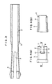
- Fig 1 shows a cross sectional view of the container of an embodiment of this invention
- Fig 2 shows a cross sectional view cut along II - II line in Fig 1 at knocked state.
- Figs 1,2. 1 is a outer sleeve
- 2 is an inner sleeve inserted in the outer sleeve 1.
- a chuck 4 is provided at the end of the inner sleeve 2.
- the chuck 4 is formed by two divided pieces but may by three divided pieces as shown in Fig 3. 7 is a slit of the chuck 4.
- a chuck ring 5 engaging with the end of the outer sleeve 1 is inserted between the chuck 4 and outer sleeve 1, connecting holes 6 are provided at the opposite sides and the rear part of the chuck ring 5, a projection 9 and a insert 10 are provided on the outer sleeve 1 at the part opposing to said connecting hole 6, the projection 9 is to contact with a bar shaped article 8 in the inner sleeve 2 through the connecting hole 6 and a split 7 of the chuck 4, the insert 10 is slidable and connectable against said connecting hole 6.
- 11 is a stopper for preventing the escapement of the insert 10 from the connecting hole 6 when the insert 10 is connected to the connecting hole 6.
- the stopper 11 has slanted edges so as to guide the insert 10 into the connecting hole 6.
- the insert 10 also has slanted edges so as to be introduced easily into the connecting hole 6.
- the elestic member 3 acting in axial direction is provided between said inner sleeve 2 and outer sleeve 1.
- the elestic member 3 is a knock spring inserted between a receiver 13 of the inner sleeve 2 and a receiver 12 of the insert 10 of the outer sleeve 1. If the receiver 12 of the insert 10 is not sufficient, a ring plate or another receivers 14,14 as shown Figs 5 and 6b in dotted line are provided. These receivers 14,14 are at right angle position against the receivers 12,12. In this case, said chuck ring 5 must provide slits at positions corresponding to said receivers 14,14.
- an erasing gum, a lead of pencil, a crayon, a pastel, eye brow are used as the bar shaped article 8.
- the article 8 is inserted into the inner sleeve 2 from rear or front end and the end of the article 8 contacts with the projection 9.
- the outer sleeve 1 is holded by hand and knock the rear end of the inner sleeve 2 against the spring 3, the chuck 4 and article 8 holded by the chuck 4 is forwarded by a predetermined amount and chuck ring 5 also forwarded until the stopper 11 of the connecting hole 6 contacts to the insert 10.
- the chuck 4 opens. In this state, the projection 9 engages with the article 8 and hold the article 8 in the position so as to prevent the escapement and returning of the article 8.
- the inner sleeve 2 retract by the resilient force of the spring 3 until the chuck ring 5 contacts with the end of the outer sleeve 1. Then, the chuck 4 is inserted into the chuck ring 5 and closes and hold the article 8 together with the projection 9.
- the article 8 By repeating the knocking operation, the article 8 can be drawn out for use.
- Fig 7 shows an outer sleeve of another embodiment of this invention.
- Figs 8 a,8 b are cross sectional views along VIIIa - VIIIa line and VIIIb - VIIIb line respectively.
- U shaped slits 15,15 are provided on the outer sleeve 1 and resilient tongues 16,16 are formed and the projections 9,9 are provided at the ends of the inner face of the tongues 16,16.
- the inserts 10, 10 having receiver 12 are positioned at an right angle against the tongues 16,16.
- the chuck ring 5 should have slits at a position corresponding to said projections 9,9 and connecting holes 6,6 and slits at a positions corresponding to said insert 10,10 and receivers 12,12.
- the projections 9,9 are flexibly provided by the displacement of the tongues 16,16 so that the forwarding or retracting movement of the article 8 are smoothly performed and variation of the diameter of the article 8 can be absorbed.
- the bar shaped article 8 set in the inner sleeve 2 can be drawn out or fed by predetermined amount by repeating the knocking operation of the rear end of the inner sleeve 2 and opening or closing the chuck 4 by chuck rings 5, and may be drawn in by pressing the end of the article 8 at the opened state of the chuck 4. So that this invention provides a compact and good handling working out container of bar shaped article.
- every article can be drawn out from the container and consumed without residual and contaminating another object such as hand but settimg time of the article 8.
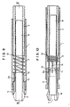
- Fig 9 shows a cross sectional view of the container of an embodiment of this invention
- Fig 10 shows a cross sectional view cut along X - X line in Fig 9 at knocked state.
- Figs 9,10. 1 is a outer sleeve
- 2 is an inner sleeve inserted in the outer sleeve 1.
- a chuck 4 is provided at the end of the inner sleeve 2.
- the chuck 4 is formed by two divided pieces but may by three divided pieces as shown Fig 3. 7 is a slit of the chuck 4.
- a chuck sleeve 5 engaging with the end of the outer sleeve 1 is inserted between the chuck 4 and outer sleeve 1, connecting bores 6 are provided at the opposite sides and the rear part of the chuck sleeve 5, a resilient member 9a and a insert 10 are provided on the outer sleeve 1 at the part opposing to said connecting bore 6, the resilient member 9a is to contact with a bar shaped article 8 in the inner sleeve 2 through the connecting bore 6 and a split 7 of the chuck 4, the insert 10 is slidable and connectable against said connecting bore 6.
- 11 is a stopper for preventing the escapement of the insert 10 from the connecting bore 6 when the insert 10 is connected to the connecting bore 6.
- the stopper 11 has slanted edges so as to guide the insert 10 into the connecting bore 6.
- the insert 10 also has slanted edges so as to be introduced easily into the connecting bore 6.
- an elastic member 3 acting in axial direction is provided between said inner sleeve 2 and outer sleeve 1.
- the elastic member 3 is a knock spring inserted between a receiver 13 of the inner sleeve 2 and a receiver 12 of the insert 10 of the outer sleeve 1. If the receiver 12 of the insert 10 is not sufficient, a ring plate or another receivers 14,14 as shown Figs 12 and 13 in dotted line are provided. These receivers 14,14 are at right angle position against the receivers 12,12. In this case, said chuck sleeve 5 must provide slits at positions corresponding to said receivers 14,14.
- the resilient member 9a is integral with the elastic member 3 but it may be flat spring or elastic member such as gum provided between knock spring 3 and sprimg receiver 12 as shown in Fig 14.
- an erasing gum, a lead of pencil, a crayon, a pastel, eye brow are used as the bar shaped article 8.
- the shape of the cross section of the article 8 may be circle, flat, square, polygon. The article 8 is inserted into the inner sleeve 2 from rear or front end and the article 8 contacts with the resilient member 9a.
- the outer sleeve 1 is holded by hand and knock the rear end of the inner sleeve 2 against the spring 3, the chuck 4 and article 8 holded by the chuck 4 is forwarded by a predetermined amount and chuck sleeve 5 also forwarded until the stopper 11 of the connecting bore 6 contacts to the insert 10.
- the chuck 4 opens.
- the resilient member 9a engages with the article 8 and hold the article 8 in the position so as to prevent the escapement and returning of the article 8.
- the inner sleeve 2 retract by the resilient force of the spring 3 until the chuck sleeve 5 contacts with the end of the outer sleeve 1. Then, the chuck 4 is inserted into the chuck sleeve 5 and closes and hold the article 8 together with the resilient member 9a.
- the article 8 By repeating the knocking operation, the article 8 can be drawn out for use.
- the chuck 4 opens and press the end of the article 8 against the frictional force between the article 8 and of the resilient member 9a which contacts with the article 8 by suitable force through the connecting hole 6 and slit 7, then the article 8 can be retracted smoothly.
- the resilient members 9a,9a contact with the article 8 by suitable force 16,16 so that the forwarding or retracting movement of the article 8 are smoothly and firmly performed and variation of the diameter of the article 8 can be absorbed.
- the bar shaped article 8 set in the inner sleeve 2 can be drawn out or fed by predetermined amount by repeating the knocking operation of the rear end of the inner sleeve 2 and opening or closing the chuck 4 by chuck sleeve 5, and may be drawn in by pressing the end of the article 8 at the opened state of the chuck 4 so that this invention provides a compact and good handling working out container of bar shaped article.
- the resilient members 9a,9a contacts with the article 8 by suitable force 16,16 so that the forwarding or retracting movement of the article 8 are smoothly and firmly performed and variation of the diameter of the article 8 can be absorbed.
- every article can be drawn out from the container and consumed without residual and contaminating another object such as hand but settimg time of the article 8.
- This invention the number of parts is less so that cost is low and trouble is less.
- Fig 15 shows a cross sectional view of the container of the sixth embodiment of this invention
- Fig 16 shows a cross sectional view cut along XVI-XVI line in Fig 15 at knocked state.
- Fig 17 shows a cross sectinal of the inner sleeve cut along XVII-XVII line in Fig 16 in this invention.
- Figs 15,16. 1 is a outer sleeve
- 2 is an inner sleeve inserted the outer sleeve 1.
- a chuck 4 is provided at the end of the inner sleeve 2.
- the chuck 4 is formed by two divided pieces but may by three divided pieces, As shown in Fig 18.
- 7 is a slit of the chuck 4 and the width of the slit 7 is narrow at the interior part 7a by tapered edges.
- a chuck ring 5 engaging with the end of the outer sleeve 1 is inserted between the chuck 4 and outer sleeve 1, connecting holes 6 are provided at the opposite sides and the rear part of the chuck ring 5, a projection 9 and a insert 10 are provided on the outer sleeve 1 at the part opposing to said connecting hole 6, the projection 9 is to contact with a bar shaped article 8 in the inner sleeve 2 through the connecting hole 6 and a split 7 of the chuck 4, the insert 10 is slidable and connectable against said connecting hole 5.
- 11 is a stopper for preventing the escapement of the insert 10 from the connecting hole 6 when the insert 10 is connected to the connecting hole 6.
- the stopper 11 has slanted edges so as to guide the insert 10 into the connecting hole 6.
- an elastic member 3 acting in axial direction is provided between said inner sleeve 2 and outer sleeve 1.
- the elastic member 3 is a knock spring inserted between a receiver 13 of the inner sleeve 2 and a receiver 12 of the insert 10 of the outer sleeve 1. If the receiver 12 of the insert 10 is not sufficient, a ring plate or another receivers 14,14 as shown Figs 19 and 20a,20b. These receivers 14,14 are at right angle position against the receivers 12,12. In this case, said chuck ring 5 must provide slits 17 at positions corresponding to said receivers 14,14.
- the insert 10 In drawning in state of the article 8, the insert 10 is positioned in the interior part 7a of the slit 7 and opens the chuck 4 slightly which can hold the article 8.
- an erasing gum, a lead of pencil, a crayon, a pastel, eye brow are used as the bar shaped article 8.
- the article 8 is inserted into the inner sleeve 2 from rear or front end and the end of the article 8 contacts with the projection 9.
- the projection 9 is integral with the outer sleeve 1 but may be another separated body such as gum or spring.
- the outer sleeve 1 is holded by hand and knock the rear end of the inner sleeve 2 against the spring 3 by knocking distance a
- the chuck 4 and article 8 holded by the chuck 4 is forwarded by a predetermined amount and chuck ring 5 also forwarded until the stopper 11 of the connecting hole 6 contacts to the insert 10.
- the chuck 4 opens. In this state, the projection 9 engages with the article 8 and hold the article 8 in the position so as to prevent the escapement and returning of the article 8.
- the inner sleeve 2 retract by the resilient force of the spring 3 until the chuck ring 5 contacts with the end of the outer sleeve 1. Then, the chuck 4 is inserted into the chuck ring 5 and closes and hold the article 8 together with the projection 9.
- the article 8 By repeating the knocking operation, the article 8 can be drawn out for use.
- the chuck opens surely by chuck opening means and press the end of the article 8 against the frictional force between the article 8 and the end of the projection 9 which contacts with the article 8 but not encroaching through the connecting hole 6 and slit 7, then the article 8 can be retracted smoothly.
- the interior part 7a of the slit 7 of the chuck 4 is narrow so that the chuck 4 is slightly opened by the insert 10 of the outer sleeve 1 at retracted position, the chuck 4 does not encroach into the article 8 even if the article 8 is soft and resilient material and leaved long time in non use state, the chuck 4 separates from the article 8 easily, the article 8 can be drawn out surely.
- anothe container may be used.
- Fig 7 shows a cross sectional view of the eighth embodiment of this invention. and Figs 22a,22b are cross sectional views along XXIIa - XXIIa line and XXIIb - XXIIb line respectively.
- a projection 18 to be entered into the intertior part 7a is provided at the inner face of the chuck ring 5.
- the chuck 4 is opened slightly by entering the projection 18 into the interior part 7a at the retracted state, so that the chuck 4 does not encroach into the article 8 as well as the first embodiment even if the article 8 is soft and resilient material and leaved long time in non use state, the chuck 4 separates from the article 8 easily, the article 8 can be drawn out surely.
- the chuck 4 is opened by entering the insert 10 or the projection 18 enters into the narrower interior part 7a at the retracted state, so that the chuck 4 does not encroach into the article 8 as well as the first embodiment even if the article 8 is soft and resilient material and resilient material and leaved long time in non use state, the chuck 4 separates from the article 8 easily, the article 8 can be drawn out surely.
- every article can be drawn out from the container and consumed without residual and contaminating another object such as hand but settimg time of the article 8.
Landscapes
- Engineering & Computer Science (AREA)
- Mechanical Engineering (AREA)
- Mechanical Pencils And Projecting And Retracting Systems Therefor, And Multi-System Writing Instruments (AREA)
- Packaging Of Annular Or Rod-Shaped Articles, Wearing Apparel, Cassettes, Or The Like (AREA)
Applications Claiming Priority (6)
| Application Number | Priority Date | Filing Date | Title |
|---|---|---|---|
| JP2609787U JPH0344552Y2 (fr) | 1987-02-23 | 1987-02-23 | |
| JP26097/87 | 1987-02-23 | ||
| JP6556087U JPH051425Y2 (fr) | 1987-04-28 | 1987-04-28 | |
| JP65560/87 | 1987-04-28 | ||
| JP108497/87 | 1987-07-14 | ||
| JP1987108497U JPH051426Y2 (fr) | 1987-07-14 | 1987-07-14 |
Publications (2)
| Publication Number | Publication Date |
|---|---|
| EP0280220A1 true EP0280220A1 (fr) | 1988-08-31 |
| EP0280220B1 EP0280220B1 (fr) | 1991-10-09 |
Family
ID=27285262
Family Applications (1)
| Application Number | Title | Priority Date | Filing Date |
|---|---|---|---|
| EP88102517A Expired - Lifetime EP0280220B1 (fr) | 1987-02-23 | 1988-02-20 | Instrument pour transformer un article en forme de barre |
Country Status (5)
| Country | Link |
|---|---|
| US (1) | US4856693A (fr) |
| EP (1) | EP0280220B1 (fr) |
| DE (1) | DE3865317D1 (fr) |
| ES (1) | ES2027331T3 (fr) |
| MX (1) | MX168765B (fr) |
Cited By (8)
| Publication number | Priority date | Publication date | Assignee | Title |
|---|---|---|---|---|
| EP0524600A1 (fr) * | 1991-07-23 | 1993-01-27 | KOTOBUKI & CO., LTD. | Récipient pour faire sortir une substance en forme de baton |
| FR2765149A1 (fr) * | 1997-06-30 | 1998-12-31 | Val De Marne Atel Du | Crayon porte-mines |
| EP1808308A1 (fr) * | 2006-01-13 | 2007-07-18 | Kotobuki & Co. Ltd. | Distributeur à propulsion pour matériel sous forme de bâton |
| EP1977660A1 (fr) * | 2007-04-03 | 2008-10-08 | Kotobuki & Co., Ltd | Récipient propulsant d'un matériel sous forme de bâton |
| EP1919716A4 (fr) * | 2005-07-26 | 2010-01-13 | Biss Product Dev Llc | Stylo mecanique |
| ITMI20090536A1 (it) * | 2009-04-03 | 2010-10-04 | Chromavis Spa | Prodotto cosmetico multifunzionale in forma di matita con elemento truccante intercambiabile |
| US8096016B2 (en) | 2005-03-15 | 2012-01-17 | Sakura Color Products Corporation | Holder for holding a stick-shaped body so as to advance said body and combination of said holder and a stick-shaped body |
| CN110077146A (zh) * | 2018-05-16 | 2019-08-02 | 张济人 | 一种无笔帽的泛用型圆珠笔壳 |
Families Citing this family (15)
| Publication number | Priority date | Publication date | Assignee | Title |
|---|---|---|---|---|
| JPH0537451U (ja) * | 1991-10-22 | 1993-05-21 | 日本ミクロコーテイング株式会社 | 円盤状デイスク固定装置 |
| US5362166A (en) * | 1993-06-28 | 1994-11-08 | Kotobuki & Co., Ltd. | Flat stick-shaped material propelling container |
| US5598604A (en) * | 1995-05-08 | 1997-02-04 | Ho; Kun-Chuan | Pencil-shaped eraser |
| US6500732B1 (en) | 1999-08-10 | 2002-12-31 | Silicon Genesis Corporation | Cleaving process to fabricate multilayered substrates using low implantation doses |
| US20040086317A1 (en) * | 2001-03-26 | 2004-05-06 | Hanna Tania W. | Holder for releasably holding conventional cosmetic tools |
| US6505984B2 (en) | 2001-04-27 | 2003-01-14 | Binney & Smith Inc. | Crayon with eraser |
| US6565275B2 (en) | 2001-04-27 | 2003-05-20 | Binney & Smith Inc. | Marker with eraser |
| US6547465B1 (en) | 2002-01-22 | 2003-04-15 | Shoot The Moon Products Ii, Llc | Pencil with exposable eraser |
| US7232270B1 (en) * | 2003-07-28 | 2007-06-19 | Goldstein Cassidy L | Device for holding writing instruments |
| US8162967B1 (en) * | 2003-10-16 | 2012-04-24 | Biomet Sports Medicine Llc | Method and apparatus for coring and reaming of bone |
| DE102005014469B4 (de) * | 2005-03-30 | 2007-01-04 | Schwan-Stabilo Cosmetics Gmbh & Co. Kg | Verfahren zum Herstellen eines Stiftes und Stift |
| US20070245515A1 (en) * | 2006-04-24 | 2007-10-25 | Liberty Japan Limited | Holder for rod shaped body |
| TWD121497S1 (zh) | 2006-09-22 | 2008-02-21 | 壽股份有限公司 | 條狀物送出容器 |
| US8641718B2 (en) | 2010-10-19 | 2014-02-04 | Biomet Manufacturing, Llc | Method and apparatus for harvesting cartilage for treatment of a cartilage defect |
| JP7701067B2 (ja) * | 2021-11-25 | 2025-07-01 | プラス株式会社 | 消しゴムケース |
Citations (4)
| Publication number | Priority date | Publication date | Assignee | Title |
|---|---|---|---|---|
| US2358091A (en) * | 1944-01-22 | 1944-09-12 | Moore Pen Company | Mechanical pencil |
| CH288755A (de) * | 1952-09-01 | 1953-02-15 | Lanz Hans | Druckstift für Radiergummieinsätze. |
| DE1090138B (de) * | 1955-08-10 | 1960-09-29 | Baier & Koeppel K G | Schreibstift |
| US3998558A (en) * | 1972-12-08 | 1976-12-21 | A. W. Faber-Castell | Mechanical pencil |
Family Cites Families (9)
| Publication number | Priority date | Publication date | Assignee | Title |
|---|---|---|---|---|
| US271439A (en) * | 1883-01-30 | Berjsthard eybel | ||
| US372710A (en) * | 1887-11-08 | Tiieodoe o | ||
| US240399A (en) * | 1881-04-19 | Charles frederick | ||
| US253803A (en) * | 1882-02-14 | Eudolp wittmasn | ||
| US223467A (en) * | 1880-01-13 | Doefee | ||
| US1702780A (en) * | 1925-07-07 | 1929-02-19 | Robt H Ingersoll Inc | Mechanical pencil |
| DE737818C (de) * | 1940-02-21 | 1943-07-24 | Koh I Noor Bleistiftfabrik L & | Fuellbleistift mit durch eine Druckkappe verschiebbarem Spitzenkoerper und Minenfuehrungsrohr |
| CH262818A (fr) * | 1947-09-10 | 1949-07-31 | Caran D Ache Crayons | Porte-mines. |
| GB2023508B (en) * | 1978-06-14 | 1982-04-28 | Chun Liang Kuo | Writing implement |
-
1988
- 1988-02-16 MX MX010437A patent/MX168765B/es unknown
- 1988-02-20 ES ES198888102517T patent/ES2027331T3/es not_active Expired - Lifetime
- 1988-02-20 EP EP88102517A patent/EP0280220B1/fr not_active Expired - Lifetime
- 1988-02-20 DE DE8888102517T patent/DE3865317D1/de not_active Expired - Lifetime
- 1988-02-23 US US07/159,258 patent/US4856693A/en not_active Expired - Lifetime
Patent Citations (4)
| Publication number | Priority date | Publication date | Assignee | Title |
|---|---|---|---|---|
| US2358091A (en) * | 1944-01-22 | 1944-09-12 | Moore Pen Company | Mechanical pencil |
| CH288755A (de) * | 1952-09-01 | 1953-02-15 | Lanz Hans | Druckstift für Radiergummieinsätze. |
| DE1090138B (de) * | 1955-08-10 | 1960-09-29 | Baier & Koeppel K G | Schreibstift |
| US3998558A (en) * | 1972-12-08 | 1976-12-21 | A. W. Faber-Castell | Mechanical pencil |
Cited By (12)
| Publication number | Priority date | Publication date | Assignee | Title |
|---|---|---|---|---|
| EP0524600A1 (fr) * | 1991-07-23 | 1993-01-27 | KOTOBUKI & CO., LTD. | Récipient pour faire sortir une substance en forme de baton |
| FR2765149A1 (fr) * | 1997-06-30 | 1998-12-31 | Val De Marne Atel Du | Crayon porte-mines |
| US8096016B2 (en) | 2005-03-15 | 2012-01-17 | Sakura Color Products Corporation | Holder for holding a stick-shaped body so as to advance said body and combination of said holder and a stick-shaped body |
| EP1919716A4 (fr) * | 2005-07-26 | 2010-01-13 | Biss Product Dev Llc | Stylo mecanique |
| EP1808308A1 (fr) * | 2006-01-13 | 2007-07-18 | Kotobuki & Co. Ltd. | Distributeur à propulsion pour matériel sous forme de bâton |
| US7878726B2 (en) | 2006-01-13 | 2011-02-01 | Kotobuki & Co., Ltd. | Stick-shaped material propelling container |
| EP1977660A1 (fr) * | 2007-04-03 | 2008-10-08 | Kotobuki & Co., Ltd | Récipient propulsant d'un matériel sous forme de bâton |
| US8348535B2 (en) | 2007-04-03 | 2013-01-08 | Kotobuki & Co., Ltd. | Stick-shaped material propelling container |
| CN101279563B (zh) * | 2007-04-03 | 2013-05-08 | 株式会社寿 | 棒状物伸出容器 |
| ITMI20090536A1 (it) * | 2009-04-03 | 2010-10-04 | Chromavis Spa | Prodotto cosmetico multifunzionale in forma di matita con elemento truccante intercambiabile |
| EP2238860A1 (fr) * | 2009-04-03 | 2010-10-13 | CHROMAVIS S.p.A. | Produit cosmétique multifonction sous forme de crayon doté d'un élément de maquillage interchangeable |
| CN110077146A (zh) * | 2018-05-16 | 2019-08-02 | 张济人 | 一种无笔帽的泛用型圆珠笔壳 |
Also Published As
| Publication number | Publication date |
|---|---|
| US4856693A (en) | 1989-08-15 |
| MX168765B (es) | 1993-06-07 |
| EP0280220B1 (fr) | 1991-10-09 |
| DE3865317D1 (de) | 1991-11-14 |
| ES2027331T3 (es) | 1992-06-01 |
Similar Documents
| Publication | Publication Date | Title |
|---|---|---|
| EP0280220A1 (fr) | Instrument pour transformer un article en forme de barre | |
| EP0513874A2 (fr) | Instrument pour écrire | |
| EP0212530A1 (fr) | Outil tranchant | |
| US3708235A (en) | Marking instrument | |
| DE2821625A1 (de) | Mechanischer schreibstift | |
| DE3803527A1 (de) | Spender | |
| US6039485A (en) | Double-chuck mechanical pencil | |
| US5193927A (en) | Mechanical pencil having propelling device for a bar shaped article | |
| US4729684A (en) | Mechanical pencil | |
| US5052838A (en) | Mechanical pencil | |
| AU538921B2 (en) | Tool holder | |
| JP2562933Y2 (ja) | 棒状物繰り出し容器 | |
| JPH051425Y2 (fr) | ||
| JPH0545513Y2 (fr) | ||
| EP1120285B1 (fr) | Support pour taille-crayon | |
| GB2298608A (en) | Drawing pin insertion tool | |
| EP0530227B1 (fr) | Porte-mine | |
| CZ282696A3 (en) | Writing instrument | |
| DE202007001572U1 (de) | Markiergerät | |
| KR900000674Y1 (ko) | 봉심(棒芯) 송출케이스 | |
| EP0032651B1 (fr) | Porte-mines à poussoir | |
| JPH0347907Y2 (fr) | ||
| JP2527958Y2 (ja) | 棒状物繰り出し容器 | |
| US4844639A (en) | Push-type writing instrument | |
| JPH0356398Y2 (fr) |
Legal Events
| Date | Code | Title | Description |
|---|---|---|---|
| PUAI | Public reference made under article 153(3) epc to a published international application that has entered the european phase |
Free format text: ORIGINAL CODE: 0009012 |
|
| AK | Designated contracting states |
Kind code of ref document: A1 Designated state(s): DE ES FR GB IT |
|
| 17P | Request for examination filed |
Effective date: 19890119 |
|
| 17Q | First examination report despatched |
Effective date: 19900521 |
|
| GRAA | (expected) grant |
Free format text: ORIGINAL CODE: 0009210 |
|
| AK | Designated contracting states |
Kind code of ref document: B1 Designated state(s): DE ES FR GB IT |
|
| REF | Corresponds to: |
Ref document number: 3865317 Country of ref document: DE Date of ref document: 19911114 |
|
| ITF | It: translation for a ep patent filed | ||
| ET | Fr: translation filed | ||
| REG | Reference to a national code |
Ref country code: ES Ref legal event code: FG2A Ref document number: 2027331 Country of ref document: ES Kind code of ref document: T3 |
|
| PLBE | No opposition filed within time limit |
Free format text: ORIGINAL CODE: 0009261 |
|
| STAA | Information on the status of an ep patent application or granted ep patent |
Free format text: STATUS: NO OPPOSITION FILED WITHIN TIME LIMIT |
|
| 26N | No opposition filed | ||
| PGFP | Annual fee paid to national office [announced via postgrant information from national office to epo] |
Ref country code: GB Payment date: 19980209 Year of fee payment: 11 |
|
| PG25 | Lapsed in a contracting state [announced via postgrant information from national office to epo] |
Ref country code: GB Free format text: LAPSE BECAUSE OF NON-PAYMENT OF DUE FEES Effective date: 19990220 |
|
| GBPC | Gb: european patent ceased through non-payment of renewal fee |
Effective date: 19990220 |
|
| PGFP | Annual fee paid to national office [announced via postgrant information from national office to epo] |
Ref country code: ES Payment date: 20000209 Year of fee payment: 13 |
|
| PG25 | Lapsed in a contracting state [announced via postgrant information from national office to epo] |
Ref country code: ES Free format text: LAPSE BECAUSE OF NON-PAYMENT OF DUE FEES Effective date: 20010221 |
|
| PGFP | Annual fee paid to national office [announced via postgrant information from national office to epo] |
Ref country code: FR Payment date: 20010228 Year of fee payment: 14 |
|
| PG25 | Lapsed in a contracting state [announced via postgrant information from national office to epo] |
Ref country code: FR Free format text: LAPSE BECAUSE OF NON-PAYMENT OF DUE FEES Effective date: 20021031 |
|
| REG | Reference to a national code |
Ref country code: ES Ref legal event code: FD2A Effective date: 20021016 |
|
| REG | Reference to a national code |
Ref country code: FR Ref legal event code: ST |
|
| PG25 | Lapsed in a contracting state [announced via postgrant information from national office to epo] |
Ref country code: IT Free format text: LAPSE BECAUSE OF NON-PAYMENT OF DUE FEES;WARNING: LAPSES OF ITALIAN PATENTS WITH EFFECTIVE DATE BEFORE 2007 MAY HAVE OCCURRED AT ANY TIME BEFORE 2007. THE CORRECT EFFECTIVE DATE MAY BE DIFFERENT FROM THE ONE RECORDED. Effective date: 20050220 |
|
| PGFP | Annual fee paid to national office [announced via postgrant information from national office to epo] |
Ref country code: DE Payment date: 20070430 Year of fee payment: 20 |