EP0280333A2 - Unité arithmétique-logique à voies optiques croisées - Google Patents
Unité arithmétique-logique à voies optiques croisées Download PDFInfo
- Publication number
- EP0280333A2 EP0280333A2 EP88102935A EP88102935A EP0280333A2 EP 0280333 A2 EP0280333 A2 EP 0280333A2 EP 88102935 A EP88102935 A EP 88102935A EP 88102935 A EP88102935 A EP 88102935A EP 0280333 A2 EP0280333 A2 EP 0280333A2
- Authority
- EP
- European Patent Office
- Prior art keywords
- optical
- light
- paths
- optical paths
- region
- Prior art date
- Legal status (The legal status is an assumption and is not a legal conclusion. Google has not performed a legal analysis and makes no representation as to the accuracy of the status listed.)
- Withdrawn
Links
Images




Classifications
-
- G—PHYSICS
- G06—COMPUTING OR CALCULATING; COUNTING
- G06F—ELECTRIC DIGITAL DATA PROCESSING
- G06F7/00—Methods or arrangements for processing data by operating upon the order or content of the data handled
-
- G—PHYSICS
- G02—OPTICS
- G02F—OPTICAL DEVICES OR ARRANGEMENTS FOR THE CONTROL OF LIGHT BY MODIFICATION OF THE OPTICAL PROPERTIES OF THE MEDIA OF THE ELEMENTS INVOLVED THEREIN; NON-LINEAR OPTICS; FREQUENCY-CHANGING OF LIGHT; OPTICAL LOGIC ELEMENTS; OPTICAL ANALOGUE/DIGITAL CONVERTERS
- G02F3/00—Optical logic elements; Optical bistable devices
-
- G—PHYSICS
- G06—COMPUTING OR CALCULATING; COUNTING
- G06E—OPTICAL COMPUTING DEVICES
- G06E1/00—Devices for processing exclusively digital data
- G06E1/02—Devices for processing exclusively digital data operating upon the order or content of the data handled
- G06E1/06—Devices for processing exclusively digital data operating upon the order or content of the data handled for performing computations using a digital non-denominational number representation, i.e. number representation without radix; using combinations of denominational and non-denominational number representations
- G06E1/065—Devices for processing exclusively digital data operating upon the order or content of the data handled for performing computations using a digital non-denominational number representation, i.e. number representation without radix; using combinations of denominational and non-denominational number representations using residue arithmetic
Definitions
- This invention relates generally to optical information processing and, in particular, to an optical cross bar technique for performing parallel optical logic and arithmetic operations.
- optical circuits in which the information carriers are photons, and electronic circuits, where the carriers are electrons. In the former case the carriers do not interact with each other, while in the latter they do.
- optical devices there exist interconnect possibilities that do not exist with electronic hardware, in particular, interconnected parallel architectures.
- the invention described herein uses this type of architecture to perform digital arithmetic and logic operations in a completely parallel, single step process. After the inputs are switched on, the output appears in the time it takes a photon to transit the device. No faster computation time is possible.
- the invention described herein relies on a mathematical framework similar to that described in the application of C.D. Capps and R.A. Falk, entitled “Parallel Optical Arithmetic/Logic Unit", Attorney Docket No. 86CAP805DAB, filed concurrently herewith and incorporated herein by reference.
- the above- mentioned disclosure incorporates parallel optical Fourier transform pattern recognition to determine the spacing between the two lighted sources of a linear set of equidistant, coherent point sources.
- this technique provides for the determination of the elements of any n by n logic truth table that can be permuted to be anti-diagonal. In particular, residue addition and multiplication can be performed.
- each "bit" in the representation is independent of the other.
- residue arithmetic does not have a "carry” operation; that is, each "bit” in the representation is independent of the other.
- each "bit" in a representation of a number is the decimal value of the number modulo the prime number corresponding to that position, called the "radix".
- the present invention uses crossed optical paths of light to represent truth table inputs and computes the table value in a single step by determining the intensity of light at the intersection of two optical paths.
- the technique eliminates the need for lenses and filters, and will function with both coherent and incoherent light inputs.
- This technique uses n2 non-linear threshold elements to evaluate an n by n truth table. Since typical values of n will be less than 30 (adequate for residue representation of 32 bit numbers, for example) the number of required threshold elements is readily produced by modern thin film fabrication methods.
- Input 100 from Channel 1 and input 200 from Channel 2 transmit light in optical paths 101 and 201 respectively to intersect at a region designated by reference number 300.
- Inputs 100 and 200 may comprise light sources coupled directly or indirectly to the optical paths 101 and 201 respectively.
- the level of liqht intensity at intersection region 300 is equivalent to two units of light.
- the level of light intensity detected at intersecting regions 301 and 302 is only one unit of light, and the level of light intensity detected at intersecting region 303 is zero.
- Figs. 2 and 3 Some examples of possible truth tables that can be realized by the present invention are shown in Figs. 2 and 3.
- Figs. 2a and 2b show examples of the kinds of two level logic tables associated with standard Boolean algebra, the AND and EXCLUSIVE-OR tables respectively.
- Fig. 2c shows an example of a multi-value logic table, specifically showing a table for radix 3 residue addition. The lack of carry operations is apparent, and thus makes parallel processing of residue addition possible.
- Figure 3a shows a radix 5 residue multiplication table and Fig.
- 3b indicates how the reduced table (with zeros removed) can be made anti-diagonal via permutation, as discussed by Szabo and Tanaka in Residue Arithmetic and its Applications to Computer Technology , McGraw-Hill, New York, 1977 and incorporated herein by reference.
- These tables are representative examples only as it is apparent that all possible multi-level logic tables can be constructed in a similar fashion.
- FIG. 4 A first possible optical embodiment of the EXCLUSIVE-OR operation is shown in Fig. 4.
- a spherical lens 1 in combination with a cylindrical lens 3 can be used to convert an input point source 5 (such as an LED, LD, etc.) into a line 7 of light.
- This line 7 can be used as one of four cross bar inputs in a spatial pattern of horizontal and vertical line images transmitted along optical paths 20, 21 and 10, 11 respectively, as shown in Fig. 4b.
- Detectors 32, 34, 36 and 38 placed at the intersecting regions of the optical paths will see either 0, 1, or 2 units of light (equal input powers assumed) when one optical path from each channel is transmitting.
- Fig. 4a A first possible optical embodiment of the EXCLUSIVE-OR operation is shown in Fig. 4.
- Detectors 32, 34, 36 and 38 placed at the intersecting regions of the optical paths will see either 0, 1, or 2 units of light (equal input powers assumed) when one optical path from each channel is transmitting.
- a line light image is transmitted along path 10 of Channel 1 (corresponding to a logic "0" state) and along path 21 of Channel 2 (corresponding to a logic "1" state).
- the detector 34 detects the double light intensity corresponding to the correct output of the EXCLUSIVE-OR operation.
- Electronic thresholding may be used as a method of discriminating the correct intensity levels and thus the correct output or desired answer for the logical operation.
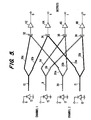
- FIG. 5 A second possible optical embodiment of the EXCLUSIVE-OR operation is shown in Fig. 5.
- This embodiment is equivalent to that shown in Fig. 4, except that fiber optics for detector illumination replace lenses 1 and 3 used in Fig. 4a and thereby form the optical paths 10, 11, 20 and 21.
- Each optical path 10, 11, 20 and 21 defined by the fiber optics is split into two individual optical paths also defined by the fiber optics, as shown, for example, by paths 10a and 10b for optical path 10.
- paths 10a and 10b direct transmitted light from an LED 13 towards detectors 32 and 34 respectively.
- Paths 21a and 21b direct transmitted light from an LED 19 towards detectors 34 and 38 respectively.
- LED's 15 and 17 are used for directing light along paths 11a, 11b and 20a and 20b to respective detectors 36, 38 (for LED 15) and 32, 36 (for LED 17). Assuming for the representative EXCLUSIVE-OR operation that only LED's 13 and 19 are energized, light from paths 10b and 21a are crossed at detector 34 whereby detector 34 detects two units of light to be discriminated by threshold unit 44. Threshold units 42, 46 and 48 are likewise connected to their corresponding detectors 32, 36 and 38, respectively.
- a significant advantage of the implementation in Fig. 5 is reduced alignment sensitivity and increased ease of packaging.
- optical waveguides 51a-51d define optical paths 10, 11, 20 and 21 respectively, and are made to intersect at optical bistable devices 50a-50d as shown.
- the optical bistable devices 50a-50d are non-linear devices which can perform an AND operation, i.e., they only turn on when two light inputs are present.
- the bistable device 50c permits the transmission of light, indicated by arrows 62, from a sampling beam designated by arrows 60 only when an intersecting region of the device 50c has two units of light crossing. For the example shown, this will only occur where path intersects path 20.
- FIG. 7 An example of a fiber optic radix 3 adder for realizing the multi-value logic table of Fig. 2c is shown in Fig. 7.
- LED module 70 transmits light through an optical fiber 72 to a power divider 74 where the intensity of the transmitted light is divided equally between optical fibers 76a, 76b and 76c.
- Fibers 76a, 76b and 76c define optical paths leading to detectors 78a, 78b and 78c respectively.
- Each of the detectors 78a, 78b and 78c also receives a second optical path from one of the Channel 2 inputs in such a way that the optical paths from Channel 1 and 2 intersect.
- Each of the detectors 78a-78c is indicative of a result in the multi-level logic table shown in Fig. 2c.
- both the integrated optics (Fig. 6) and the optical and electronic (Fig. 7) embodiments will achieve the desired result, although the integrated optics version utilizing the cross bar technique is able to operate at significantly higher speeds.
- the R-C time constants of the electronic interconnects shown in Fig. 7 will limit the response time to values on the order of 1 nsec.
- the speed of the integrated optics device is primarily limited only by the response time of the final non-linear AND operation.
- the integrated optics configuration would thus permit high speed operation with demonstrated optical bistable switching speeds of 10's of psec (e.g., GaAs multi-quantum well devices).
- the described invention has utility not only in computer applications, but also in certain specialized applications, such as high speed encrypting.
- the cross bar optical technique uses n2 non-linear threshold elements to evaluate an n by n truth or multi-level logic table. Since typical values of n will be less than 30 for adequate residue representation of, for example, 32 bit numbers, the number of required threshold elements may be easily produced by current thin film fabrication methods.
Landscapes
- Engineering & Computer Science (AREA)
- Physics & Mathematics (AREA)
- Theoretical Computer Science (AREA)
- General Physics & Mathematics (AREA)
- Computing Systems (AREA)
- Nonlinear Science (AREA)
- Optics & Photonics (AREA)
- General Engineering & Computer Science (AREA)
- Optical Modulation, Optical Deflection, Nonlinear Optics, Optical Demodulation, Optical Logic Elements (AREA)
- Photometry And Measurement Of Optical Pulse Characteristics (AREA)
Applications Claiming Priority (2)
| Application Number | Priority Date | Filing Date | Title |
|---|---|---|---|
| US07/019,761 US5010505A (en) | 1987-02-27 | 1987-02-27 | Optical cross bar arithmetic/logic unit |
| US19761 | 1987-02-27 |
Publications (2)
| Publication Number | Publication Date |
|---|---|
| EP0280333A2 true EP0280333A2 (fr) | 1988-08-31 |
| EP0280333A3 EP0280333A3 (fr) | 1991-04-03 |
Family
ID=21794889
Family Applications (1)
| Application Number | Title | Priority Date | Filing Date |
|---|---|---|---|
| EP19880102935 Withdrawn EP0280333A3 (fr) | 1987-02-27 | 1988-02-26 | Unité arithmétique-logique à voies optiques croisées |
Country Status (5)
| Country | Link |
|---|---|
| US (1) | US5010505A (fr) |
| EP (1) | EP0280333A3 (fr) |
| JP (1) | JPS63229438A (fr) |
| KR (1) | KR880010360A (fr) |
| AU (1) | AU1060688A (fr) |
Cited By (2)
| Publication number | Priority date | Publication date | Assignee | Title |
|---|---|---|---|---|
| EP0378833A1 (fr) * | 1988-12-21 | 1990-07-25 | The Boeing Company | Méthode et appareil pour effectuer une comparaison arithmétique-optique à entrées multiples |
| US5191549A (en) * | 1988-12-21 | 1993-03-02 | The Boeing Company | Method and apparatus for performing a multiple-input optical arithmetic comparison |
Families Citing this family (7)
| Publication number | Priority date | Publication date | Assignee | Title |
|---|---|---|---|---|
| US6898343B2 (en) | 2001-08-17 | 2005-05-24 | Fujitsu Limited | Optical switching apparatus and method for fabricating |
| US6922508B2 (en) * | 2001-08-17 | 2005-07-26 | Fujitsu Limited | Optical switching apparatus with adiabatic coupling to optical fiber |
| US20070233761A1 (en) * | 2006-04-03 | 2007-10-04 | Mouttet Blaise L | Crossbar arithmetic processor |
| US9965251B2 (en) * | 2006-04-03 | 2018-05-08 | Blaise Laurent Mouttet | Crossbar arithmetic and summation processor |
| US9939711B1 (en) | 2013-12-31 | 2018-04-10 | Open Portal Enterprises (Ope) | Light based computing apparatus |
| US10545529B1 (en) | 2014-08-11 | 2020-01-28 | OPē, LLC | Optical analog numeric computation device |
| US9948454B1 (en) | 2015-04-29 | 2018-04-17 | Open Portal Enterprises (Ope) | Symmetric data encryption system and method |
Family Cites Families (8)
| Publication number | Priority date | Publication date | Assignee | Title |
|---|---|---|---|---|
| US3476459A (en) * | 1965-10-23 | 1969-11-04 | Sperry Rand Corp | Optical logic system with a screen made of photochromic material |
| US3680080A (en) * | 1970-06-29 | 1972-07-25 | Optical Memory Systems | Optical logic function generator |
| US3996455A (en) * | 1974-05-08 | 1976-12-07 | The United States Of America As Represented By The Administrator Of The National Aeronautics And Space Administration | Two-dimensional radiant energy array computers and computing devices |
| SU579618A1 (ru) * | 1975-03-25 | 1977-11-05 | Институт математики и механики АН Казахской ССР | Устройство дл умножени |
| DE2619307A1 (de) * | 1976-04-30 | 1977-11-10 | Inst Mat I Mekh Akademii Nauk | Multipliziereinrichtung |
| US4363106A (en) * | 1980-08-13 | 1982-12-07 | Environmental Research Institute Of Michigan | Computation module for addition and multiplication in residue arithmetic |
| US4569033A (en) * | 1983-06-14 | 1986-02-04 | The United States Of America As Represented By The Secretary Of The Navy | Optical matrix-matrix multiplier based on outer product decomposition |
| JPS60260925A (ja) * | 1984-06-07 | 1985-12-24 | Omron Tateisi Electronics Co | 光and回路 |
-
1987
- 1987-02-27 US US07/019,761 patent/US5010505A/en not_active Expired - Fee Related
-
1988
- 1988-01-20 AU AU10606/88A patent/AU1060688A/en not_active Abandoned
- 1988-02-25 JP JP63040920A patent/JPS63229438A/ja active Pending
- 1988-02-26 EP EP19880102935 patent/EP0280333A3/fr not_active Withdrawn
- 1988-02-27 KR KR1019880002041A patent/KR880010360A/ko not_active Withdrawn
Cited By (2)
| Publication number | Priority date | Publication date | Assignee | Title |
|---|---|---|---|---|
| EP0378833A1 (fr) * | 1988-12-21 | 1990-07-25 | The Boeing Company | Méthode et appareil pour effectuer une comparaison arithmétique-optique à entrées multiples |
| US5191549A (en) * | 1988-12-21 | 1993-03-02 | The Boeing Company | Method and apparatus for performing a multiple-input optical arithmetic comparison |
Also Published As
| Publication number | Publication date |
|---|---|
| KR880010360A (ko) | 1988-10-08 |
| JPS63229438A (ja) | 1988-09-26 |
| US5010505A (en) | 1991-04-23 |
| AU1060688A (en) | 1988-09-01 |
| EP0280333A3 (fr) | 1991-04-03 |
Similar Documents
| Publication | Publication Date | Title |
|---|---|---|
| Guilfoyle et al. | High-speed low-energy digital optical processors | |
| US6151428A (en) | All-optical wavelength coded logic gates | |
| Ha et al. | Parallel modified signed-digit arithmetic using an optoelectronic shared content-addressable-memory processor | |
| EP0350760A2 (fr) | Unité arithmétique-logique électro-optique intégrée et procédé pour sa fabrication | |
| US5010505A (en) | Optical cross bar arithmetic/logic unit | |
| Li et al. | Content-addressable-memory-based single-stage optical modified-signed-digit arithmetic | |
| HK1001009B (en) | Method of and device for recognizing optically encoded signals | |
| Goutzoulis et al. | Optical processing with residue LED/LD lookup tables | |
| US4910699A (en) | Optical computer including parallel residue to binary conversion | |
| Craig et al. | Optical cellular logic image processor: implementation and programming of a single channel digital optical circuit | |
| US6778303B2 (en) | N-valued optical logic architecture and method | |
| Walker et al. | Optoelectronic systems based on InGaAs–complementary-metal-oxide-semiconductor smart-pixel arrays and free-space optical interconnects | |
| US4948959A (en) | Optical computer including pipelined conversion of numbers to residue representation | |
| Basuray et al. | A tristate optical logic system | |
| Fey et al. | Specification for a reconfigurable optoelectronic VLSI processor suitable for digital signal processing | |
| Beyette Jr et al. | Bitonic sorting using an optoelectronic recirculating architecture | |
| Gonza´ lez-Marcos et al. | Method to analyze the influence of hysteresis in optical arithmetic units | |
| US5121249A (en) | Fiber optic computational network utilizing optical and/or gate employing non-linear organic polymers and photovoltaic/piezoelectric optical interfaces | |
| Li et al. | Optical on-the-fly conversion of a modified signed digit into two’s complement binary number representation | |
| Cathey et al. | High concurrency data bus using arrays of optical emitters and detectors | |
| EP4473451B1 (fr) | Procédé destiné à calculer optiquement des fonctions booléennes à m entrées et système de calcul électro-optique associé | |
| RU2044338C1 (ru) | Логическое устройство, реализующее операции maximum & minimum | |
| Ghosh et al. | Binary to modified trinary number system conversion and vice-versa for optical super computing | |
| US5155619A (en) | Optical AND/OR gate employing non-linear organic polymers and photovoltaic/piezoelectric optical interfaces | |
| US5045681A (en) | Optoelectric ripple carry adder |
Legal Events
| Date | Code | Title | Description |
|---|---|---|---|
| PUAI | Public reference made under article 153(3) epc to a published international application that has entered the european phase |
Free format text: ORIGINAL CODE: 0009012 |
|
| AK | Designated contracting states |
Kind code of ref document: A2 Designated state(s): AT BE CH DE ES FR GB GR IT LI LU NL SE |
|
| RBV | Designated contracting states (corrected) |
Designated state(s): DE FR GB SE |
|
| PUAL | Search report despatched |
Free format text: ORIGINAL CODE: 0009013 |
|
| AK | Designated contracting states |
Kind code of ref document: A3 Designated state(s): AT BE CH DE ES FR GB GR IT LI LU NL SE |
|
| STAA | Information on the status of an ep patent application or granted ep patent |
Free format text: STATUS: THE APPLICATION IS DEEMED TO BE WITHDRAWN |
|
| 18D | Application deemed to be withdrawn |
Effective date: 19911005 |