EP0280395B1 - Procédé et dispositif pour la fabrication de courroies - Google Patents
Procédé et dispositif pour la fabrication de courroies Download PDFInfo
- Publication number
- EP0280395B1 EP0280395B1 EP88300532A EP88300532A EP0280395B1 EP 0280395 B1 EP0280395 B1 EP 0280395B1 EP 88300532 A EP88300532 A EP 88300532A EP 88300532 A EP88300532 A EP 88300532A EP 0280395 B1 EP0280395 B1 EP 0280395B1
- Authority
- EP
- European Patent Office
- Prior art keywords
- mandrel
- segments
- tube
- flexible tube
- axis
- Prior art date
- Legal status (The legal status is an assumption and is not a legal conclusion. Google has not performed a legal analysis and makes no representation as to the accuracy of the status listed.)
- Expired - Lifetime
Links
- 238000004519 manufacturing process Methods 0.000 title description 8
- 238000005520 cutting process Methods 0.000 claims description 29
- 238000000034 method Methods 0.000 claims description 16
- 230000008878 coupling Effects 0.000 description 4
- 238000010168 coupling process Methods 0.000 description 4
- 238000005859 coupling reaction Methods 0.000 description 4
- 229910052782 aluminium Inorganic materials 0.000 description 3
- XAGFODPZIPBFFR-UHFFFAOYSA-N aluminium Chemical compound [Al] XAGFODPZIPBFFR-UHFFFAOYSA-N 0.000 description 3
- 239000000463 material Substances 0.000 description 3
- 108091008695 photoreceptors Proteins 0.000 description 3
- 239000000758 substrate Substances 0.000 description 3
- 238000009966 trimming Methods 0.000 description 3
- 238000000576 coating method Methods 0.000 description 2
- 230000007812 deficiency Effects 0.000 description 2
- 230000005484 gravity Effects 0.000 description 2
- 238000003466 welding Methods 0.000 description 2
- DHKHKXVYLBGOIT-UHFFFAOYSA-N 1,1-Diethoxyethane Chemical compound CCOC(C)OCC DHKHKXVYLBGOIT-UHFFFAOYSA-N 0.000 description 1
- 229920004943 Delrin® Polymers 0.000 description 1
- 230000001133 acceleration Effects 0.000 description 1
- 239000011354 acetal resin Substances 0.000 description 1
- 230000004913 activation Effects 0.000 description 1
- 238000010923 batch production Methods 0.000 description 1
- 230000006835 compression Effects 0.000 description 1
- 238000007906 compression Methods 0.000 description 1
- 238000010276 construction Methods 0.000 description 1
- 230000003247 decreasing effect Effects 0.000 description 1
- 238000003384 imaging method Methods 0.000 description 1
- 229910052751 metal Inorganic materials 0.000 description 1
- 239000002184 metal Substances 0.000 description 1
- 229920006324 polyoxymethylene Polymers 0.000 description 1
- 238000002360 preparation method Methods 0.000 description 1
- 229920005992 thermoplastic resin Polymers 0.000 description 1
Images
Classifications
-
- B—PERFORMING OPERATIONS; TRANSPORTING
- B26—HAND CUTTING TOOLS; CUTTING; SEVERING
- B26D—CUTTING; DETAILS COMMON TO MACHINES FOR PERFORATING, PUNCHING, CUTTING-OUT, STAMPING-OUT OR SEVERING
- B26D3/00—Cutting work characterised by the nature of the cut made; Apparatus therefor
- B26D3/16—Cutting rods or tubes transversely
- B26D3/161—Cutting rods or tubes transversely for obtaining more than one product at a time
-
- B—PERFORMING OPERATIONS; TRANSPORTING
- B26—HAND CUTTING TOOLS; CUTTING; SEVERING
- B26D—CUTTING; DETAILS COMMON TO MACHINES FOR PERFORATING, PUNCHING, CUTTING-OUT, STAMPING-OUT OR SEVERING
- B26D7/00—Details of apparatus for cutting, cutting-out, stamping-out, punching, perforating, or severing by means other than cutting
- B26D7/20—Cutting beds
- B26D2007/202—Rollers or cylinders being pivoted during operation
-
- Y—GENERAL TAGGING OF NEW TECHNOLOGICAL DEVELOPMENTS; GENERAL TAGGING OF CROSS-SECTIONAL TECHNOLOGIES SPANNING OVER SEVERAL SECTIONS OF THE IPC; TECHNICAL SUBJECTS COVERED BY FORMER USPC CROSS-REFERENCE ART COLLECTIONS [XRACs] AND DIGESTS
- Y10—TECHNICAL SUBJECTS COVERED BY FORMER USPC
- Y10T—TECHNICAL SUBJECTS COVERED BY FORMER US CLASSIFICATION
- Y10T82/00—Turning
- Y10T82/16—Severing or cut-off
- Y10T82/16016—Processes
-
- Y—GENERAL TAGGING OF NEW TECHNOLOGICAL DEVELOPMENTS; GENERAL TAGGING OF CROSS-SECTIONAL TECHNOLOGIES SPANNING OVER SEVERAL SECTIONS OF THE IPC; TECHNICAL SUBJECTS COVERED BY FORMER USPC CROSS-REFERENCE ART COLLECTIONS [XRACs] AND DIGESTS
- Y10—TECHNICAL SUBJECTS COVERED BY FORMER USPC
- Y10T—TECHNICAL SUBJECTS COVERED BY FORMER US CLASSIFICATION
- Y10T82/00—Turning
- Y10T82/16—Severing or cut-off
- Y10T82/16229—Interrelated means for tool infeed and circumrotation
Definitions
- This invention relates in general to apparatus and processes for fabricating flexible belts.
- Reinforced belts have been cut from a belt-band by supporting the belt-band on two parallel cylinders that are moved away from each other to stretch the belt-band for cutting. Each end of each cylinder is supported to maintain the parallel relationship of the cylinders during stretching of the belt-band. This approach is time-consuming and cumbersome because at least one end of each cylinder must be separated from its support to permit loading and unloading of the belt-band from the cylinders. Moreover, at least one of the cylinders must be sequentially moved toward, away from, and toward the other cylinder to permit loading stretching and unloading, respectively, of the belt-band.
- Belts can also be prepared from continuous webs by slicing the webs lengthwise, cutting the sliced webs into short segments and thereafter welding opposite ends of the webs together.
- This involves a batch process that consumes considerable time, requires duplicate manual handling, occupies excessive floor space and necessitates extensive equipment for alignment, cutting, welding trimming and other processing steps.
- the resulting belt has a seam which is highly undesirable for many applications.
- US-A-1,986,587 a technique for sectionalizing tubes in which an expansible tube is placed within a rotatable carrier and is rotated so that centrifugal forces cause the tube to expand within the rotating carrier. A severing force is then applied by a cutting edge to that portion of the expansible tube projecting beyond one end of rotating carrier such that the expanded tube is cut.
- US-A-3,576,147 discloses a belt cutter comprising a disc-shaped cutting member which is rotated against a disc-shaped anvil to cut an endless belt into narrower strips.
- US-A-4,292,867 discloses an apparatus and method for slitting elongated rolls of material in which a roll of web material is rolled on a tubular core and a slitting assembly comprising a circular knife blade and circular saw blade is controlled so as to cut the roll into plural strips.
- US-A-3,107,563 discloses an apparatus for cutting belt bands comprising an endless belt which is mounted on rotatable support means. A cutter engages the belt, to cut it into individual strips.
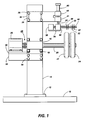
- a base plate 10 upon which is mounted by bolts 12 a vertical beam post 14.
- a bearing plate 16 is bolted to post 14 by bolts 18.
- Bearing plate 16 supports a rotatable shaft 20.
- Cylindrical mandrels 22 and 24 are mounted on an end of shaft 20.
- a variable speed electric motor 26 is coupled to the other end of shaft 20 through a conventional coupling device, such as Lovejoy coupling 28. If desired, any suitable coupling device, such as a universal, may be substituted for the Lovejoy coupling.
- Motor 26 is mounted on a plate 30 which is welded to a support bracket 32.
- Support bracket 32 is secured to post 14 by bolts 34.
- a cutter support bracket 36 is fastened to post 14 by means of bolts 38.
- Brackets 39 are provided in bracket 36 to permit adjustment in a vertical direction.
- Bearing supports 40 and 41 welded to the bifurcated end of bracket 36 support a slidable shaft 42 having a square cross-section.
- a bearing support 44 welded to the lower end of shaft 42 supports a horizontal rotatable cutter shaft 46.
- Cutting disks 48, 50, 52, and 54 are mounted on on end of shaft 46.
- a plate 56 is welded to the bottom of bearing support 44. The plate 56 supports a cutter shaft drive motor 58 which is coupled directly to cutter shaft 46.
- a two-way acting pneumatic cylinder 60 is mounted on bearing support 40 and is adapted to extend and retract shaft 42 in a vertical direction.
- the cylinder 60 is placed in the extend or retract mode by means of conventional valves and suitable air hoses (not shown) connected to a source of compressed air.
- any other suitable device for extending or retracting the cutting blade may be substituted for the two-way acting pneumatic cylinder, e.g. solenoid, cam and lever arm, and the like.
- suitable conventional cutting devices such as non-rotary knife blades, rotary saw blades, and the like may be substituted for the rotary cutting disks.
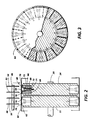
- cylindrical mandrel 22 mounted on rotatable shaft 20 carries a plurality of movable segments 62.
- Each movable segment 62 is adapted to move in a radial direction toward and away from rotatable shaft 20.
- Each movable segment 62 has an arcuate, outwardly-facing, gripping surface 63 which, together with outwardly-facing gripping surfaces of adjacent movable segments, forms a substantially cylindrical surface.
- each movable segment 62 contains a large-diameter hole 64 and a small-diameter hole 66, and is adapted to reciprocate on shouldered guide screw 68.
- Guide screw 68 has a head 70 slightly smaller than the diameter of the large-diameter hole 70.
- Guide screw 68 is screwed into the bottom 71 of annular channel 72 of movable segment 62.
- An optional coil spring 73 surrounds the portion of guide screw 68 between head 70 and the bottom of large diameter hole 64 to bias movable segments 62 radially toward shaft 20.
- Each movable segment 62 contains at least one groove 74 which, together with grooves of adjacent movable segments, forms an annular groove around cylindrical mandrel 22.
- grooves 74, 76, 78 and 80 are adapted to receive the edges of cutting blades 48, 50, 52 and 54, respectively when rotatable cutter shaft 46 is lowered toward mandrels 22 and 24.
- FIG. 2 a partial view of a flexible tube 82 is shown with the movable segments 62 radially extended away from shaft 20 so that the arcuate outwardly-facing gripping surfaces 63 of adjacent movable segments 62 form a substantially-cylindrical surface in contact with the inner surface of flexible tube 82. In the extended position, the bottom 84 of each segment 62 is spaced from the bottom 71 of annular channel 72.
- variable-speed electric motor 26 In operation, electrical power to variable-speed electric motor 26 is initially off, by appropriate turning of control knob of a conventional potentiometer (not shown). Since the cylindrical mandrels 22 and 24 are stationary, each movable segment 62 is in a retracted position because each coil spring 72 biases the movable segments 62 radially toward shaft 20. Since the segments 62 are in a retracted position, the substantially-cylindrical surface defined by the arcuate outwardly-facing gripping surfaces 63 of the movable segments 62 has a perimeter that is smaller than the substantially-cylindrical surface defined by the arcuate outwardly-facing gripping surfaces 63 when the movable segments 62 are in an extend position.
- the smaller perimeter of the substantially-cylindrical surface defined by the arcuate outwardly-facing gripping surfaces 63 is also smaller than the inside perimeter of the flexible tube 82 to facilitate sliding of the flexible tube 82 over mandrels 22 and 24 for subsequent cutting.
- the two-way acting pneumatic cylinder 60 is in a retracted mode to provide sufficient clearance between the cutting blades 48, 50, 52 and 54 and mandrels 22 and 24 during loading of flexible tube 82 onto mandrels 22 and 24.
- power is supplied to rotate shaft 20 at a speed sufficient to cause centrifugal force to drive the movable segments 62 radially away from shaft 20 and to compress coil springs 73.
- the outwardly-facing gripping surfaces 63 of the radially extended segments 62 grip the inner surface of flexible tube 82 to hold it immobile relative to the extended segments 62.
- Electric power is then supplied to motor 58 by activation of a conventional switch (not shown) to cause shaft 46 to rotate.
- Compressed air is thereafter supplied to the upper end of two-way acting pneumatic cylinder 60 to lower the lower edge of cutting blades 48, 50, 52 and 54 through one side of flexible tube 82 into grooves 74, 76, 78 and 80, respectively.
- the cutting blades 48, 50, 52 and 54 circumferentially slice the flexible tube 82 into separate belts.
- the supply of compressed air to the upper end of two-way acting pneumatic cylinder 60 is diverted by a suitable conventional valve (not shown) to the lower end of two-way acting pneumatic cylinder 60 thereby raising cutting blades 48, 50, 52 and 54 away from mandrels 22 and 24.
- Power supplied to motor 26 is terminated and the segments 62 are allowed to return to the retracted position because of the bias supplied by the springs 73.
- the sliced sections of the flexible tube 82 are thereafter readily removed from mandrels 22 and 24.
- the optional compression type coil springs 72 may be substituted for other suitable means for retracting the segments 62.
- tension coil springs that pull rather than push the segments 62 toward shaft 20.
- at least one large circular coil spring may be placed in a deep channel extending around the periphery of segments 62 to encircle all the segments 62 and bias the segments 62 toward shaft 20.
- suitable two-way actuators such as solenoids, pneumatic cylinders or hydraulic cylinders, may be substituted for coil springs 72.
- the omission of coil springs or other biasing devices is preferred because of the simplicity, size and low cost of the devices.
- the mandrel During loading of an unbiased mandrel, the mandrel is stationary and the top segments are retracted, because of gravity. The bottom segments are lifted by the operator as the tube is slid onto the mandrel with a rotating action. If desired, stationary knife blades may be substituted for the rotating disk-shaped cutting blades 48, 50, 52 and 54.
- mandrels are shown in the drawings, any suitable number of mandrels may be used. Further, the mandrels may be spaced from each other as shown in the Figures, closely adjacent to, or in contact with, each other. Moreover, the grooves in the segments may be of any desired number depending upon the width of the segments and width being sought. The grooves in the segments are essential because the outer diameter of the segments often describe a slightly-varying true circle during operation. Thus, the grooves provide the flexibility required to accommodate any variations of the belt internal diameter.
- the speed of rotation of the mandrels depends upon numerous factors, such as the diameter of the mandrel, weight of the segments, strength of the coil springs, distance that the segments, must move, resilience of the flexible tube, and the like. However, the speed of rotation of the mandrels should be sufficient to allow centrifugal force to drive the movable segments radially away from shaft ,and so that the outwardly-facing gripping surfaces of the radially-extended segments grip the inner surface of flexible tube to hold it immobile relative to the extended segments.
- a flexible seamless, tube of thermoplastic resin having a thickness of about 0.2 mm, a length of about 180 mm and an inside perimeter of about 330 mm was manually fed over a disk-shaped mandrel.
- the mandrel was similar in construction to the mandrel illustrated in Figs. 2 and 3, and comprised an acetal resin (Delrin, available from E. I. du Pont de Nemours & Co.).
- the mandrel had three wide parallel grooves to hold three parallel rings of segments. Each segment was aluminum and was 65 mm ⁇ 45 mm at the bottom, 65 mm ⁇ 60 mm at the top, and the radial distance from the bottom to the top was about 50 mm.
- Each segment had a pair of parallel grooves having a rectangular cross-section, with a width at the top of about 1.3 mm and a depth of about 5 mm. These grooves were 2.5 mm apart and were parallel to each face of the disk-shaped mandrel.
- the mandrel had an outside circumference of about 330 mm when the segments were extended.
- the mandrel was mounted on a shaft supported at one end in the chuck of a metal lathe. The other free end of the shaft was temporarily supported by a bearing block during the cutting operation.
- the bearing block was adapted to slide away from the end of the shaft to facilitate sliding of the flexible seamless tube onto the mandrel.
- This apparatus occupied a floor space of about 1.5 meters ⁇ 3.6 meters. No biasing devices were used for the segments.
- the mandrel was stationary and the top segments were retracted because of gravity.
- the bottom segments were lifted by the operator as the flexible tube was slid onto the mandrel with a rotating action.
- the shaft carrying the mandrel and tube was rotated at 800 rpm to force the aluminum segments radially outwardly on shouldered guide screws from the axis of the mandrel by centrifugal force.
- the segments moved radially outwardly away from the shaft until the gripping surfaces of the segments firmly gripped and tautly supported the interior of the flexible tube.
- Slitting disks supported on a common shaft revolving at about 10,000 RPM were positioned opposite the circumferential grooves in the gripping surface of the segments and moved toward the axis of the mandrel to slice the seamless tube into belts.
- the five newly-formed belts and scrap end material were removed from the mandrel after the lathe was stopped.
- the resulting belts were free of creases and the outside surfaces were undamaged.
- precise belt widths with a tolerance of ⁇ 0.125 mm was achieved.
- the apparatus and process of this invention minimizes the equipment needed for alignment, cutting, trimming and other processing of the belts.
- the apparatus and process of this invention achieve greater uniform belt quality.
- This process was repeated with a mandrel having five channels carrying aluminum segments to produce 11 belts.
- the 11 resulting belts were also free of creases and exhibited precise belt widths with a tolerance of ⁇ 0.125 mm.
- This apparatus was thereafter converted, within a period of about one hour, to fabricate belts of a different width by merely changing the mandrel and alligning cutting blades opposite the circumferential grooves in the gripping surface of the segments.
- the apparatus and process of this invention can cut flexible tubes in less time without contacting the outside surface of the tubes thereby decreasing the likelihood of damage to delicate tubes or coatings thereon, particularly for coated substrates that demand precision tolerances. Moreover the apparatus of this invention occupies little floor space and minimizes the equipment needed for alignment, cutting, trimming and other processing of the belts. In addition, the apparatus and process of this invention achieve greater uniform belt quality. Also, because of differences in belt size requirements for different applications, the apparatus of this invention can be rapidly and easily converted from fabricating a belt of one diameter or width to preparing a belt of a different diameter or width by merely changing the mandrel and position of the cutting blades. Moreover, the characteristics of belt fabrication systems of this invention exhibit are capable of manufacturing belts of different widths and diameters within precise tolerance standards.
Landscapes
- Life Sciences & Earth Sciences (AREA)
- Forests & Forestry (AREA)
- Engineering & Computer Science (AREA)
- Mechanical Engineering (AREA)
- Nonmetal Cutting Devices (AREA)
Claims (9)
- Dispositif pour fabriquer des courroies souples comprenant au moins un mandrin cylindrique (22, 24) comportant une multitude de segments mobiles (62) disposés autour de la périphérie du mandrin, chaque segment comportant une surface de serrage faisant face vers l'extérieur (63) qui coopère avec les surfaces de serrage contigues sur les segments contigus pour former une surface pratiquement cylindrique comportant au moins une rainure annulaire (74, 76, 78, 80) qui entoure la surface pratiquement cylindrique, un moyen (68) pour guider chaque segment à mesure qu'il se déplace radialement par rapport à l'axe du mandrin, un moyen pour tourner le mandrin, au moins un outil de découpe (48, 50, 52, 54) contigu à et séparé de la rainure et un moyen pour déplacer l'outil de découpe ou les outils de découpe et la surface cylindrique les uns par rapport aux autres, si bien que l'outil de découpe entoure le mandrin le long d'un trajet aligné avec la rainure.
- Dispositif selon la revendication 1, dans lequel la surface de serrage faisant face vers l'extérieur comporte au moins deux rainures annulaires.
- Dispositif selon la revendication 1 ou 2, comportant un moyen (73) pour déplacer les segments radialement vers l'axe du mandrin.
- Dispositif selon la revendication 3, dans lequel le moyen de sollicitation pour déplacer les segments radialement vers l'axe du mandrin comprend un ressort en spirale.
- Dispositif selon l'une quelconque des revendications précédentes, dans lequel les segments sont prévus pour être déplacés radialement loin de l'axe du mandrin par la force centrifuge produite par la rotation du mandrin.
- Procédé pour fabriquer des courroies souples comprenant les étapes consistant à délivrer un tube souple (82) comportant une paroi mince, introduire au moins un mandrin (22, 24) à l'intérieur du tube comportant une surface extérieure cylindrique dilatable ayant une surface de serrage extérieure (63), dilater le mandrin jusqu'à ce que les surfaces de serrage extérieures viennent en contact par frottement avec la surface intérieure du tube souple, découper le tube souple à partir de l'extérieur le long d'au moins un trajet qui entoure le tube, pour former un segment de tube et rétracter le mandrin pour éliminer le contact des surfaces de serrage à partir de la surface intérieure du tube souple.
- Procédé selon la revendication 6, dans lequel le mandrin est dilaté en appliquant une force centrifuge suffisante à celui-ci pour déplacer les segments mobiles de celui-ci radialement loin de l'axe du mandrin.
- Procédé selon la revendication 6 ou 7, comportant l'enlèvement des segments de tube à partir du mandrin après qu'il ait été rétracté.
- Procédé selon l'une quelconque des revendications 6 à 8, comportant la découpe du tube souple simultanément le long d'une multitude de trajets parallèles qui entourent le tube, afin de former une multitude de segments de tube.
Applications Claiming Priority (2)
| Application Number | Priority Date | Filing Date | Title |
|---|---|---|---|
| US17398 | 1987-02-24 | ||
| US07/017,398 US4766789A (en) | 1987-02-24 | 1987-02-24 | Apparatus and process for preparing belts |
Publications (3)
| Publication Number | Publication Date |
|---|---|
| EP0280395A2 EP0280395A2 (fr) | 1988-08-31 |
| EP0280395A3 EP0280395A3 (en) | 1989-11-29 |
| EP0280395B1 true EP0280395B1 (fr) | 1992-06-17 |
Family
ID=21782368
Family Applications (1)
| Application Number | Title | Priority Date | Filing Date |
|---|---|---|---|
| EP88300532A Expired - Lifetime EP0280395B1 (fr) | 1987-02-24 | 1988-01-22 | Procédé et dispositif pour la fabrication de courroies |
Country Status (5)
| Country | Link |
|---|---|
| US (1) | US4766789A (fr) |
| EP (1) | EP0280395B1 (fr) |
| JP (1) | JPH0643104B2 (fr) |
| CA (1) | CA1305044C (fr) |
| DE (1) | DE3871983T2 (fr) |
Families Citing this family (5)
| Publication number | Priority date | Publication date | Assignee | Title |
|---|---|---|---|---|
| US5820897A (en) * | 1995-07-27 | 1998-10-13 | Xerox Corporation | Apparatus for handling and dippling flexible belts using a blow molded polymer chucking device |
| DE19602730A1 (de) * | 1996-01-26 | 1997-07-31 | Brodbeck Maschb Gmbh | Vorrichtung zum Schneiden von Rohren |
| US6418822B1 (en) * | 2000-06-27 | 2002-07-16 | Sonoco Development, Inc. | Cut-off apparatus for non-circular tubes |
| DE102006009203A1 (de) * | 2006-02-24 | 2007-08-30 | Arntz Beteiligungs Gmbh & Co. Kg | Rotierend antreibbares Schneid- bzw. Fräswerkzeug zum Bearbeiten zäher, elastischer oder platischer Materialien |
| CN109176623B (zh) * | 2018-09-10 | 2024-03-12 | 闳诚科技有限公司 | 一种环状弹性带的裁切机装置 |
Family Cites Families (11)
| Publication number | Priority date | Publication date | Assignee | Title |
|---|---|---|---|---|
| DD64884A (fr) * | ||||
| US465075A (en) * | 1891-12-15 | John walter grantland | ||
| US1758729A (en) * | 1929-01-25 | 1930-05-13 | Goodrich Co B F | Method and apparatus for severing elastic tubular articles |
| US1986587A (en) * | 1932-04-08 | 1935-01-01 | Ball Brothers Co | Method of sectionalizing tubes |
| US2661579A (en) * | 1949-09-06 | 1953-12-08 | Dayton Rubber Company | Belt dressing and cutting device |
| US3107563A (en) * | 1960-06-08 | 1963-10-22 | Us Rubber Co | Apparatus for cutting belt-bands |
| US3576147A (en) * | 1969-03-12 | 1971-04-27 | Eltec Inc | Belt cutter |
| US3818576A (en) * | 1970-09-08 | 1974-06-25 | Goodyear Tire & Rubber | Method for manufacturing v belts |
| US3875832A (en) * | 1973-07-26 | 1975-04-08 | Johnny W Mayfield | Manual pipe bevelling tool |
| US4072072A (en) * | 1977-03-15 | 1978-02-07 | Harb Mitchell A | Dual tire cutting machine |
| US4292867A (en) * | 1979-11-06 | 1981-10-06 | Judelshon Industries Division, John Dusenbery Co., Inc. | Apparatus and method for slitting elongated rolls of material |
-
1987
- 1987-02-24 US US07/017,398 patent/US4766789A/en not_active Expired - Lifetime
- 1987-12-21 CA CA000554973A patent/CA1305044C/fr not_active Expired - Fee Related
-
1988
- 1988-01-22 EP EP88300532A patent/EP0280395B1/fr not_active Expired - Lifetime
- 1988-01-22 DE DE8888300532T patent/DE3871983T2/de not_active Expired - Lifetime
- 1988-02-17 JP JP63034950A patent/JPH0643104B2/ja not_active Expired - Fee Related
Also Published As
| Publication number | Publication date |
|---|---|
| EP0280395A3 (en) | 1989-11-29 |
| JPH0643104B2 (ja) | 1994-06-08 |
| DE3871983D1 (de) | 1992-07-23 |
| CA1305044C (fr) | 1992-07-14 |
| DE3871983T2 (de) | 1992-12-03 |
| EP0280395A2 (fr) | 1988-08-31 |
| JPS63216734A (ja) | 1988-09-09 |
| US4766789A (en) | 1988-08-30 |
Similar Documents
| Publication | Publication Date | Title |
|---|---|---|
| EP0492918B1 (fr) | Procédé de fabrication d'une couche | |
| US5391342A (en) | Method of forming an apex filler | |
| US8430351B2 (en) | Stretch film winder | |
| CN1131836C (zh) | 用于制备复卷机用的卷绕心轴和卷芯的设备和方法 | |
| EP1989137B1 (fr) | Procédé et dispositif pour préparer des noyaux de bobinages tubulaires | |
| US3654828A (en) | Tire building machine | |
| EP1582320B1 (fr) | Dispositif de serrage pour machines pour faire la coupe transversale des pièces longues de papier | |
| US5100497A (en) | Method and apparatus for forming an apex filler and/or applying an apex filler to a bead ring sub-assembly | |
| GB2062539A (en) | Apparatus and method for slitting elongated rolls of material | |
| EP0340147B1 (fr) | Dispositif pour la fabrication de pneus | |
| JPH028893B2 (fr) | ||
| EP0280395B1 (fr) | Procédé et dispositif pour la fabrication de courroies | |
| EP0214079B1 (fr) | Procédé et dispositif d'emmagasinage et d'alimentation de talons de pneus | |
| EP1297946A2 (fr) | Tambour pour la fabrication d'une carcasse de pneu et appareil comprenant ledit tambour | |
| US6723195B1 (en) | Adjustable tire building contour drum and method of building tire thereon | |
| US4172399A (en) | Method and apparatus for slitting rolled material | |
| US3791243A (en) | Method and apparatus for forming edges on an endless belt | |
| CA2326768C (fr) | Formage et application des plis de pneus | |
| US4805684A (en) | Tire tread grooving method and apparatus | |
| US3993530A (en) | Apparatus for applying belt strips to a tire carcass | |
| EP1150830B1 (fr) | Tambour avec contour de confection de pneu reglable et procede de confection de pneu sur ce tambour | |
| US5054341A (en) | Apparatus and method for trimming a can body | |
| GB2236124A (en) | Paint roller finishing and cutting machine | |
| CA1333711C (fr) | Ensemble tourelle pour transfert automatique d'etiquettes | |
| US3188254A (en) | Method and apparatus for making endless belt bodies |
Legal Events
| Date | Code | Title | Description |
|---|---|---|---|
| PUAI | Public reference made under article 153(3) epc to a published international application that has entered the european phase |
Free format text: ORIGINAL CODE: 0009012 |
|
| AK | Designated contracting states |
Kind code of ref document: A2 Designated state(s): DE FR GB |
|
| PUAL | Search report despatched |
Free format text: ORIGINAL CODE: 0009013 |
|
| AK | Designated contracting states |
Kind code of ref document: A3 Designated state(s): DE FR GB |
|
| RHK1 | Main classification (correction) |
Ipc: B29D 29/00 |
|
| 17P | Request for examination filed |
Effective date: 19900525 |
|
| 17Q | First examination report despatched |
Effective date: 19910925 |
|
| GRAA | (expected) grant |
Free format text: ORIGINAL CODE: 0009210 |
|
| AK | Designated contracting states |
Kind code of ref document: B1 Designated state(s): DE FR GB |
|
| REF | Corresponds to: |
Ref document number: 3871983 Country of ref document: DE Date of ref document: 19920723 |
|
| ET | Fr: translation filed | ||
| PLBE | No opposition filed within time limit |
Free format text: ORIGINAL CODE: 0009261 |
|
| STAA | Information on the status of an ep patent application or granted ep patent |
Free format text: STATUS: NO OPPOSITION FILED WITHIN TIME LIMIT |
|
| 26N | No opposition filed | ||
| REG | Reference to a national code |
Ref country code: GB Ref legal event code: IF02 |
|
| PGFP | Annual fee paid to national office [announced via postgrant information from national office to epo] |
Ref country code: FR Payment date: 20030110 Year of fee payment: 16 |
|
| PGFP | Annual fee paid to national office [announced via postgrant information from national office to epo] |
Ref country code: GB Payment date: 20030122 Year of fee payment: 16 |
|
| PGFP | Annual fee paid to national office [announced via postgrant information from national office to epo] |
Ref country code: DE Payment date: 20030130 Year of fee payment: 16 |
|
| PG25 | Lapsed in a contracting state [announced via postgrant information from national office to epo] |
Ref country code: GB Free format text: LAPSE BECAUSE OF NON-PAYMENT OF DUE FEES Effective date: 20040122 |
|
| PG25 | Lapsed in a contracting state [announced via postgrant information from national office to epo] |
Ref country code: DE Free format text: LAPSE BECAUSE OF NON-PAYMENT OF DUE FEES Effective date: 20040803 |
|
| GBPC | Gb: european patent ceased through non-payment of renewal fee |
Effective date: 20040122 |
|
| PG25 | Lapsed in a contracting state [announced via postgrant information from national office to epo] |
Ref country code: FR Free format text: LAPSE BECAUSE OF NON-PAYMENT OF DUE FEES Effective date: 20040930 |
|
| REG | Reference to a national code |
Ref country code: FR Ref legal event code: ST |