EP0280399B1 - Gewendeltes Gerät - Google Patents
Gewendeltes Gerät Download PDFInfo
- Publication number
- EP0280399B1 EP0280399B1 EP88300587A EP88300587A EP0280399B1 EP 0280399 B1 EP0280399 B1 EP 0280399B1 EP 88300587 A EP88300587 A EP 88300587A EP 88300587 A EP88300587 A EP 88300587A EP 0280399 B1 EP0280399 B1 EP 0280399B1
- Authority
- EP
- European Patent Office
- Prior art keywords
- coil
- cleaning
- turns
- rotor
- earth working
- Prior art date
- Legal status (The legal status is an assumption and is not a legal conclusion. Google has not performed a legal analysis and makes no representation as to the accuracy of the status listed.)
- Expired - Lifetime
Links
Images



Classifications
-
- A—HUMAN NECESSITIES
- A01—AGRICULTURE; FORESTRY; ANIMAL HUSBANDRY; HUNTING; TRAPPING; FISHING
- A01B—SOIL WORKING IN AGRICULTURE OR FORESTRY; PARTS, DETAILS, OR ACCESSORIES OF AGRICULTURAL MACHINES OR IMPLEMENTS, IN GENERAL
- A01B29/00—Rollers
- A01B29/06—Rollers with special additional arrangements
-
- A—HUMAN NECESSITIES
- A01—AGRICULTURE; FORESTRY; ANIMAL HUSBANDRY; HUNTING; TRAPPING; FISHING
- A01B—SOIL WORKING IN AGRICULTURE OR FORESTRY; PARTS, DETAILS, OR ACCESSORIES OF AGRICULTURAL MACHINES OR IMPLEMENTS, IN GENERAL
- A01B29/00—Rollers
- A01B29/04—Rollers with non-smooth surface formed of rotatably-mounted rings or discs or with projections or ribs on the roller body; Land packers
- A01B29/046—Rollers with non-smooth surface formed of rotatably-mounted rings or discs or with projections or ribs on the roller body; Land packers the soil-pressing body being a helical coil
-
- A—HUMAN NECESSITIES
- A01—AGRICULTURE; FORESTRY; ANIMAL HUSBANDRY; HUNTING; TRAPPING; FISHING
- A01B—SOIL WORKING IN AGRICULTURE OR FORESTRY; PARTS, DETAILS, OR ACCESSORIES OF AGRICULTURAL MACHINES OR IMPLEMENTS, IN GENERAL
- A01B71/00—Construction or arrangement of setting or adjusting mechanisms, of implement or tool drive or of power take-off; Means for protecting parts against dust, or the like; Adapting machine elements to or for agricultural purposes
- A01B71/08—Means for protecting against dust or the like, or for cleaning agricultural implements
Definitions
- the present invention relates to an earth working apparatus.
- a number of forms of apparatus used for earth working include an elongate helical coil mounted on a frame for rotation about the longitudinal axis of the coil relative to the frame.
- the coil rotates about a substantially horizontal axis by the effect of contact of the earth with the coil when the coil is dragged across the ground, for example by a tractor.
- the rotation of the coil may be used for example for crumbling the earth to provide a seed bed, or the apparatus may be used as a plough packer for consolidating the land after ploughing, again to provide a seed bed.
- a difficulty with such coils is that in wet conditions earth clings to the coils, blocking the coils and reducing efficiency of operation.
- Previously known attempts to clean such a coil have been made by providing a fixed scraper bar parallel to the axis of the coil and positioned close to the periphery of the coil, so as to scrape off excess earth.
- Such attempts have been unsuccessful in adequately cleaning the helical turns of the coil.
- US-A-2,300,851 discloses an earth working apparatus comprising a frame for movement over the ground, an elongate earth working rotary member mounted on the frame for rotation about the longitudinal axis of the rotary member in contact with the earth for the purposes of earth working, said rotary member having spaces on its outer surface, and means for cleaning the earth working rotary member, the cleaning means comprising a plurality of rotatable cleaning rotors each having outwardly projecting portions for projecting into said spaces of the rotary member to clean said rotary member.
- the rotary member is a horizontal cylinder bearing a series of helical grooves about its outer surface to provide said spaces.
- the grooves of the earth working cylinder are cleaned by an array of petalled wheels which mesh with the grooves in the cylinder, and appear to clean the cylinder by the tips of the petals digging dirt out of the grooves in the cylinder.
- Rotation of the grooved cylinder forces the petalled wheels to rotate by the effect of the grooves on the tips of the petals.
- cleaning of the cylinder is additionally effected by causing it to mesh with a second, similar cylinder.
- an earth working apparatus as defined above, and characterised in that said earth working rotary member comprises an elongate helical coil, said spaces on the outer surface thereof being defined between turns of the coil, in that each said cleaning rotor is rotatable about an axis transverse to the axis of the helical coil, and in that the outwardly projecting portions of each cleaning rotor protrude into said spaces between turns of the coil such that the sides of the projecting portions scrape across the sides of the turns of the coil during its rotation to thereby clean the coil.
- said cleaning rotors are arranged such that said projecting portions are generally substantially level with or below the level of a central diametral plane of said coil which extends substantially at right angles to the axes of the rotors.
- each cleaning rotor comprises outwardly projecting arms arranged such that the only contact between the cleaning rotor and the coil is contact between a side of an arm and the coil.
- each projecting portion extends sufficiently to protrude through a space between two adjacent turns of the coil beyond the inner edges of the coil turns.
- Such an arrangement allows thorough cleaning of the coil by a side of an arm scraping against the side edge of a turn of the coil, and by the projecting arm passing through the turn of the coil and thoroughly cleaning earth clinging to the coil.
- each cleaning rotor has four outwardly projecting portions positioned symmetrically about the axis of the cleaning rotor.
- each projecting portion has a main portion with side edges converging towards each other in the outward direction, and a shorter, tip portion, with side edges converging towards each other more rapidly than the convergence of the main portion.
- each projecting portion of a cleaning rotor is inclined relative to a plane perpendicular to the axis of rotation of the cleaning rotor.
- said plane may be the central diametral plane of said helical coil extending at right angles to the axes of the rotors.
- the cleaning rotors are positioned in a substantially horizontal array when the apparatus is standing on horizontal ground, and each projecting portion is inclined downwardly when protruding into a space between turns of the coil.
- each cleaning rotor may project outwardly in a radial direction, or in some arrangements may project along an axis off-set slightly from the radial position.
- each cleaning rotor is preferably itself freely rotatable about its axis of rotation, and, in operation, is rotated by the effect of turns of the helical coil on the projecting portions thereof.
- the earth working coil is driven in rotation by the effect of contact with the ground as the coil is moved over the earth.
- a cleaning system for an earth working coil which is powered entirely by the movement of the earth working helical coil over the ground, and which allows thorough cleaning of the earth working coil by the protrusion of portions of the cleaning rotors into the spaces between the turns of the coil, by a scraping action due to direct contact of the cleaning rotors against the turns of the earth working coil.
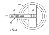
- an earth working apparatus includes a movable frame 11 arranged to be mounted on a vehicle, for example at the rear of a tractor, for movement over the land in the direction A or the direction B as indicated by arrows in Figure 1.
- the preferred direction of movement is direction A but the positioning of the moving components is that which would arise for movement in the direction B .
- a helical coil 12 is mounted by end plates 13 and 14 on a central core 15 which is journalled for rotation about the axis of the coil 12.
- the coil 12 may be of conventional design, for example a 1.5 inch square steel bar wound along a helix having a pitch of 5.5 inches. In operation the coil 12 is rotated by the effect of the coil being dragged over the ground by the tractor.
- Each rotor 16 comprises four arms 18 extending outwardly from the bolt 17, but off-set slightly from the radial position, so as to be substantially tangential to the axis of rotation of the rotor.
- Each rotor 16 is freely rotatable on its bolt 17, and the arms 18 protrude into the spaces between turns of the helical coil 12. It will be seen from Figure 2 that the arms 18 are, in general, substantially at the same level as the horizontally extending, central diametral plane of the coil 12 which is substantially at right angles to its rotation axis.
- rotation of the helical coil 12 causes the turns of the coil 12 to make contact with the arms 18 of the rotors 16, and the coil is cleaned by the scraping action of the arms 18 on the sides of the turns of the coil 12.
- the coil 12 rotates in effect the spaces between the turns of the coil move longitudinally along the coil, and the rotors 16 are rotated by the effect of contact of the turns of the coil 12 on the arms 18.
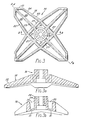
- FIGs 3a and 3b there is shown in plan and in two sections respectively an alternative preferred form of cleaning rotor 16, which may be used in place of the cleaning rotor 16 in Figures 1 and 2.
- Figures 4 and 5 correspond to previous Figures 1 and 2, and like components are indicated by like reference numerals. In general the description given with regard to Figures 1 and 2 applies also to Figures 4 and 5.
- the preferred form of cleaning rotor 16 has four arms 18 projecting outwardly from the axis of rotation of the rotor 16 in radial directions.
- Each arm 18 has a main portion 20 with sides which converge in the outward direction, and a tip portion 21 which is shorter than the main portion 20, and which has converging sides which converge more rapidly than the convergence of the main portion 20.
- each arm 18 is inclined to a plane perpendicular to the axis of rotation of the rotor, and as shown in Figure 5, each arm is inclined downwardly when the rotors are arranged in a horizontal array behind the cleaning coil.
- each arm 18 has three deep raised ribs 22, 23 and 24, linked by flat webs 25 and 26.
- the ribs 22 and 24 run along the edges of the arm 18, and the rib 23 is a central rib of the arm.
- a central core of the rotor 16 comprises a square arrangement of similar ribs 27 with an inner strengthened bearing portion of two cylindrical ribs 28 and 29.
- the core ribs 27, 28 and 29 are linked by cross ribs 30 and webs 31.
- the shape of rotor 16 shown in Figures 3, 3a and 3b, is suitable for manufacture from synthetic plastics material, the ribs giving sufficient strength for the cleaning purpose.
- the rotors 16 are mounted on a transverse frame 11 and are adjusted, for example, to give a clearance of 8mm between the outermost edge of the coil 12 and the junction of two arms 18, as shown at C in Figure 4.
- the rotors 16 are positioned so that a line 33 drawn substantially through the centre of the core of the rotor 16 projects through the axle 15 of the coil 12.
- the central diametral plane of the coil 12 can be represented by the line 33, and it will be seen that the arms 18 are generally below the level of the plane.
- each arm 18 is narrower than the distance between adjacent turns of the coil 12, so that only one side of each coil turn contacts only one side of an arm 18 of a rotor 16.
- a particularly effective scraping action takes place between the side of the protruding arm 18, and the turn of the coil 12.
- Each arm 18 extends sufficiently to protrude through the space between two adjacent turns of the coil 12 beyond the inner edge of the coil turns, when it is penetrating to its greatest extent. This protrusion of the arm through the coil, rather than just into the space between the turns, is a particularly effective in loosening of soil which is clogging the coil.
- each rotor may have a diameter of 228mm (9 inches) and may be made of self-lubricating polypropelene.
- the cleaning rotors 16 may be mounted beneath a length of box sectioned steel positioned at the rear and running the full length of the coil 12. There may be approximately four cleaning rotors per meter of coil. As the coil 12 rotates in moving across the earth, the rotors 16 automatically revolve in time with the coil and scrape off any clinging soil.
- the shape of the cleaning rotors enables the arms to project into the coil and clean inside as well as outside. Although the tips of the arms effect some cleaning within the coil, the primary effect of the cleaning rotors is that the sides of the arms clean the turns of the coil by a sliding and scraping action.
- FIG. 4a Another arrangement is shown in Figure 4a, where the cleaning rotors of Figures 3, 3a and 3b, are mounted on the apparatus previously described with reference to Figures 1 and 2.
- the positions of the cleaning rotor correspond to movement in the direction A .
Landscapes
- Life Sciences & Earth Sciences (AREA)
- Engineering & Computer Science (AREA)
- Mechanical Engineering (AREA)
- Soil Sciences (AREA)
- Environmental Sciences (AREA)
- Superconductors And Manufacturing Methods Therefor (AREA)
- Magnetic Resonance Imaging Apparatus (AREA)
- Soil Working Implements (AREA)
- Cleaning In General (AREA)
- Sampling And Sample Adjustment (AREA)
- Fuel-Injection Apparatus (AREA)
- Mushroom Cultivation (AREA)
- Fertilizers (AREA)
- Physical Deposition Of Substances That Are Components Of Semiconductor Devices (AREA)
- Cleaning By Liquid Or Steam (AREA)
- Manufacture Of Motors, Generators (AREA)
- Linear Motors (AREA)
Claims (8)
- Bodenbearbeitungsvorrichtung mit einem Rahmen (11) zur Fortbewegung über den Boden, mit einem länglichen, drehenden Teil (12), das am Rahmen (11) befestigt ist und das sich bei der Bodenbearbeitung durch Kontakt mit dem Boden um seine Längsachse dreht, wobei das drehende Teil (12) Vertiefungen in seiner Außenoberfläche aufweist, und mit einer Vorrichtung (16) zum Reinigen des drehenden Teils (12), wobei die Reinigungsvorrichtung mehrere drehbare Reinigungsrotoren (16) aufweist, die nach außen abstehende Bereiche (18) aufweisen, die in die Vertiefungen im drehenden Teil (12) hineinragen, dadurch gekennzeichnet, daß das drehende Teil eine längliche Wendel (12) aufweist, deren Windungen die Vertiefungen in der Außenoberfläche zwischen sich bilden, daß jeder Reinigungsrotor (16) um eine quer zur Achse der Wendel (12) gerichtete Achse drehbar ist, und daß die nach außen abstehenden Bereiche (18) jedes Reinigungsrotors (16) in die Vertiefungen zwischen den Windungen der Wendel (12) ragen, so daß die Seiten der nach außen abstehenden Bereiche (18) während der Drehung über die Seiten der Windungen der Wendel (12) schaben um die Wendel (12) zu reinigen.
- Vorrichtung nach Anspruch 1, dadurch gekennzeichnet, daß die Reinigungsrotoren (16) so angeordnet sind, daß sich die nach außen abstehenden Bereiche (18) im wesentlichen in oder unterhalb einer Ebene (33) befinden, die durch die Achse der Wendel (12) verläuft und die mit den Achsen der Reinigungsrotoren (16) ungefähr einen rechten Winkel bildet.
- Vorrichtung nach Anspruch 1 oder 2, dadurch gekennzeichnet, daß die abstehenden Bereiche (18) jedes Reinigungsrotors (16) nach außen abstehende Arme (18) aufweisen, die so angeordnet sind, daß die einzige Berührung zwischen Reinigungsrotor (16) und Wendel (12) eine Berührung an der Seite eines Arms (18) und der Wendel (12) ist.
- Vorrichtung nach einem der vorhergehenden Ansprüche, dadurch gekennzeichnet, daß jeder abstehende Bereich (18) tiefer als die Innenränder der Windungen der Wendel (12) in eine Vertiefung zwischen zwei benachbarten Windungen der Wendel (12) hineinragt
- Vorrichtung nach einem der vorhergehenden Ansprüche, dadurch gekennzeichnet, daß jeder Reinigungsrotor (16) vier nach außen abstehende Bereiche (18) aufweist, die symmetrisch zur Achse des Reinigungsrotors (16) angeordnet sind.
- Vorrichtung nach einem der vorhergehenden Ansprüche, dadurch gekennzeichnet, daß jeder abstehende Bereich (18) einen Hauptbereich, dessen Seiten nach außen zueinander konvergieren, und einen kürzeren Endbereich, dessen Seiten stärker zueinander konvergieren als im Hauptbereich, aufweist.
- Vorrichtung nach einem der vorhergehenden Ansprüche, dadurch gekennzeichnet, daß jeder abstehende Bereich (18) eines Reinigungsrotors (16) zu einer senkrecht zur Drehachse des Reingungsrotors (16) stehenden Ebene geneigt ist.
- Vorrichtung nach Anspruch 7, dadurch gekennzeichnet, daß die Reinigungsrotoren (16) ungefähr horizontal angeordnet sind, wenn sich die Vorrichtung auf horizontalem Boden befindet, und daß jeder abstehende Bereich (18) nach unten geneigt ist, wenn er in eine Vertiefung zwischen Windungen der Wendel (12) hineinragt.
Priority Applications (2)
| Application Number | Priority Date | Filing Date | Title |
|---|---|---|---|
| EP91116885A EP0477993B1 (de) | 1987-01-26 | 1988-01-25 | Bodenbearbeitungsvorrichtung |
| AT88300587T ATE81249T1 (de) | 1987-01-26 | 1988-01-25 | Gewendeltes geraet. |
Applications Claiming Priority (2)
| Application Number | Priority Date | Filing Date | Title |
|---|---|---|---|
| GB878701606A GB8701606D0 (en) | 1987-01-26 | 1987-01-26 | Coil apparatus |
| GB8701606 | 1987-01-26 |
Related Child Applications (1)
| Application Number | Title | Priority Date | Filing Date |
|---|---|---|---|
| EP91116885.4 Division-Into | 1991-10-03 |
Publications (3)
| Publication Number | Publication Date |
|---|---|
| EP0280399A2 EP0280399A2 (de) | 1988-08-31 |
| EP0280399A3 EP0280399A3 (en) | 1988-09-14 |
| EP0280399B1 true EP0280399B1 (de) | 1992-10-07 |
Family
ID=10611198
Family Applications (2)
| Application Number | Title | Priority Date | Filing Date |
|---|---|---|---|
| EP91116885A Expired - Lifetime EP0477993B1 (de) | 1987-01-26 | 1988-01-25 | Bodenbearbeitungsvorrichtung |
| EP88300587A Expired - Lifetime EP0280399B1 (de) | 1987-01-26 | 1988-01-25 | Gewendeltes Gerät |
Family Applications Before (1)
| Application Number | Title | Priority Date | Filing Date |
|---|---|---|---|
| EP91116885A Expired - Lifetime EP0477993B1 (de) | 1987-01-26 | 1988-01-25 | Bodenbearbeitungsvorrichtung |
Country Status (5)
| Country | Link |
|---|---|
| EP (2) | EP0477993B1 (de) |
| AT (2) | ATE108296T1 (de) |
| DE (2) | DE3875135T2 (de) |
| ES (2) | ES2035913T3 (de) |
| GB (2) | GB8701606D0 (de) |
Families Citing this family (9)
| Publication number | Priority date | Publication date | Assignee | Title |
|---|---|---|---|---|
| NL8701344A (nl) * | 1987-06-10 | 1989-01-02 | Lely Nv C Van Der | Grondbewerkingsinrichting voorzien van een rol. |
| GB8718122D0 (en) * | 1987-07-30 | 1987-09-03 | British Res Agricult Eng | Clod crumbler |
| GB8720269D0 (en) * | 1987-08-27 | 1987-10-07 | Cousins N | Tillage |
| FR2624685B1 (fr) * | 1987-12-22 | 1991-07-05 | Franquet Ets | Appareil de traitement du sol, notamment par emottage et compactage |
| GB2223387B (en) * | 1988-08-24 | 1993-01-06 | Flexi Coil | Coil apparatus |
| GB2228851B (en) * | 1989-02-14 | 1994-03-16 | Flexi Coil | Coil apparatus |
| DE69412786D1 (de) * | 1994-03-16 | 1998-10-01 | Herbert R J Eng Ltd | Verfahren und Vorrichtung um Hackfrüchternte zu Fördern |
| FR2868244B1 (fr) | 2004-04-02 | 2006-06-16 | Religieux Freres Sarl | Rouleau du type a spires pour machine de travail du sol |
| US8347824B2 (en) | 2010-06-24 | 2013-01-08 | David Christopher Marshall | Combination retractable leash assembly and wearable locket for companion pet |
Family Cites Families (6)
| Publication number | Priority date | Publication date | Assignee | Title |
|---|---|---|---|---|
| US2261893A (en) * | 1939-11-27 | 1941-11-04 | Wolfard Noah Ellsworth | Earth roller |
| US2300851A (en) * | 1939-12-14 | 1942-11-03 | Wolfard Noah Ellsworth | Earth pulverizer |
| DE2747535C2 (de) * | 1977-10-22 | 1983-11-17 | Fritz 7315 Weilheim Güttler | Stern- oder Packersternwalze |
| DE2818718A1 (de) * | 1978-04-28 | 1979-11-08 | Howard Machinery Ltd | Krumenpacker |
| DE2849891A1 (de) * | 1978-11-17 | 1980-05-22 | Weiste & Co Accord Landmasch | Bodenbearbeitungsgeraet |
| FR2488768A1 (fr) * | 1980-08-22 | 1982-02-26 | Lafforgue Jean | Dispositif pour briser les mottes de terre |
-
1987
- 1987-01-26 GB GB878701606A patent/GB8701606D0/en active Pending
-
1988
- 1988-01-25 AT AT91116885T patent/ATE108296T1/de not_active IP Right Cessation
- 1988-01-25 GB GB8801593A patent/GB2201073B/en not_active Revoked
- 1988-01-25 ES ES198888300587T patent/ES2035913T3/es not_active Expired - Lifetime
- 1988-01-25 EP EP91116885A patent/EP0477993B1/de not_active Expired - Lifetime
- 1988-01-25 DE DE8888300587T patent/DE3875135T2/de not_active Expired - Fee Related
- 1988-01-25 DE DE3850677T patent/DE3850677T2/de not_active Expired - Fee Related
- 1988-01-25 AT AT88300587T patent/ATE81249T1/de not_active IP Right Cessation
- 1988-01-25 ES ES91116885T patent/ES2061144T3/es not_active Expired - Lifetime
- 1988-01-25 EP EP88300587A patent/EP0280399B1/de not_active Expired - Lifetime
Also Published As
| Publication number | Publication date |
|---|---|
| EP0280399A2 (de) | 1988-08-31 |
| GB8801593D0 (en) | 1988-02-24 |
| EP0477993B1 (de) | 1994-07-13 |
| DE3850677T2 (de) | 1995-03-23 |
| DE3850677D1 (de) | 1994-08-18 |
| GB8701606D0 (en) | 1987-03-04 |
| GB2201073A (en) | 1988-08-24 |
| ATE108296T1 (de) | 1994-07-15 |
| EP0280399A3 (en) | 1988-09-14 |
| ES2061144T3 (es) | 1994-12-01 |
| ATE81249T1 (de) | 1992-10-15 |
| DE3875135D1 (de) | 1992-11-12 |
| DE3875135T2 (de) | 1993-05-06 |
| ES2035913T3 (es) | 1993-05-01 |
| EP0477993A1 (de) | 1992-04-01 |
| GB2201073B (en) | 1990-10-17 |
Similar Documents
| Publication | Publication Date | Title |
|---|---|---|
| US3774689A (en) | Tine cultivators with support shields | |
| US4047576A (en) | Cultivator wheel for agricultural machines | |
| EP0280399A2 (de) | Gewendeltes Gerät | |
| US3897830A (en) | Soil cultivating implements and supporting rollers | |
| US4533000A (en) | Soil cultivating implements | |
| US4417627A (en) | Apparatus for breaking rock located in a field | |
| US3338315A (en) | Soil packer and pulverizer | |
| US3841411A (en) | Cultivator and tines | |
| US4412588A (en) | Soil cultivating implements | |
| US5076367A (en) | Soil working device | |
| US4515222A (en) | Soil cultivating implements | |
| EP0383561B1 (de) | Schraubenförmige Vorrichtung | |
| EP0356083B1 (de) | Spiralgerät mit Abstreifer und Bodenbearbeitungsmaschine, das dieses Spiralgerät inkorporiert | |
| US2669173A (en) | Rotary cultivator | |
| US4342365A (en) | Soil crumbling rollers | |
| EP0294903B1 (de) | Bodenbearbeitungsmaschine mit Walze | |
| US2654982A (en) | Cultivating device | |
| DE3327362C2 (de) | ||
| US2650460A (en) | Spirally arranged toothed cultivator wheel | |
| US4151885A (en) | Soil cultivating implements | |
| US4043400A (en) | Harrows | |
| GB1592961A (en) | Soil cultivating machine | |
| GB2128461A (en) | Soil cultivating implements | |
| US4189006A (en) | Soil cultivating implements | |
| US2321537A (en) | Weeder |
Legal Events
| Date | Code | Title | Description |
|---|---|---|---|
| PUAI | Public reference made under article 153(3) epc to a published international application that has entered the european phase |
Free format text: ORIGINAL CODE: 0009012 |
|
| PUAL | Search report despatched |
Free format text: ORIGINAL CODE: 0009013 |
|
| AK | Designated contracting states |
Kind code of ref document: A2 Designated state(s): AT BE CH DE ES FR GB IT LI NL SE |
|
| AK | Designated contracting states |
Kind code of ref document: A3 Designated state(s): AT BE CH DE ES FR GB IT LI NL SE |
|
| 17P | Request for examination filed |
Effective date: 19890307 |
|
| 17Q | First examination report despatched |
Effective date: 19900702 |
|
| GRAA | (expected) grant |
Free format text: ORIGINAL CODE: 0009210 |
|
| AK | Designated contracting states |
Kind code of ref document: B1 Designated state(s): AT BE CH DE ES FR GB IT LI NL SE |
|
| PG25 | Lapsed in a contracting state [announced via postgrant information from national office to epo] |
Ref country code: SE Effective date: 19921007 Ref country code: LI Effective date: 19921007 Ref country code: CH Effective date: 19921007 |
|
| REF | Corresponds to: |
Ref document number: 81249 Country of ref document: AT Date of ref document: 19921015 Kind code of ref document: T |
|
| XX | Miscellaneous (additional remarks) |
Free format text: TEILANMELDUNG 91116885.4 EINGEREICHT AM 25/01/88. |
|
| REF | Corresponds to: |
Ref document number: 3875135 Country of ref document: DE Date of ref document: 19921112 |
|
| ITF | It: translation for a ep patent filed | ||
| REG | Reference to a national code |
Ref country code: CH Ref legal event code: PL |
|
| ET | Fr: translation filed | ||
| REG | Reference to a national code |
Ref country code: ES Ref legal event code: FG2A Ref document number: 2035913 Country of ref document: ES Kind code of ref document: T3 |
|
| PLBE | No opposition filed within time limit |
Free format text: ORIGINAL CODE: 0009261 |
|
| STAA | Information on the status of an ep patent application or granted ep patent |
Free format text: STATUS: NO OPPOSITION FILED WITHIN TIME LIMIT |
|
| 26N | No opposition filed | ||
| PGFP | Annual fee paid to national office [announced via postgrant information from national office to epo] |
Ref country code: ES Payment date: 20010228 Year of fee payment: 14 |
|
| REG | Reference to a national code |
Ref country code: GB Ref legal event code: IF02 |
|
| PG25 | Lapsed in a contracting state [announced via postgrant information from national office to epo] |
Ref country code: ES Free format text: LAPSE BECAUSE OF NON-PAYMENT OF DUE FEES Effective date: 20020126 |
|
| PGFP | Annual fee paid to national office [announced via postgrant information from national office to epo] |
Ref country code: DE Payment date: 20030129 Year of fee payment: 16 Ref country code: FR Payment date: 20030129 Year of fee payment: 16 Ref country code: BE Payment date: 20030129 Year of fee payment: 16 |
|
| PGFP | Annual fee paid to national office [announced via postgrant information from national office to epo] |
Ref country code: NL Payment date: 20030130 Year of fee payment: 16 |
|
| PGFP | Annual fee paid to national office [announced via postgrant information from national office to epo] |
Ref country code: AT Payment date: 20030131 Year of fee payment: 16 |
|
| REG | Reference to a national code |
Ref country code: ES Ref legal event code: FD2A Effective date: 20031022 |
|
| PG25 | Lapsed in a contracting state [announced via postgrant information from national office to epo] |
Ref country code: AT Free format text: LAPSE BECAUSE OF NON-PAYMENT OF DUE FEES Effective date: 20040125 |
|
| PG25 | Lapsed in a contracting state [announced via postgrant information from national office to epo] |
Ref country code: BE Free format text: LAPSE BECAUSE OF NON-PAYMENT OF DUE FEES Effective date: 20040131 |
|
| BERE | Be: lapsed |
Owner name: *FLEXI-COIL (UK) LTD Effective date: 20040131 |
|
| PG25 | Lapsed in a contracting state [announced via postgrant information from national office to epo] |
Ref country code: NL Free format text: LAPSE BECAUSE OF NON-PAYMENT OF DUE FEES Effective date: 20040801 |
|
| PG25 | Lapsed in a contracting state [announced via postgrant information from national office to epo] |
Ref country code: DE Free format text: LAPSE BECAUSE OF NON-PAYMENT OF DUE FEES Effective date: 20040803 |
|
| PG25 | Lapsed in a contracting state [announced via postgrant information from national office to epo] |
Ref country code: FR Free format text: LAPSE BECAUSE OF NON-PAYMENT OF DUE FEES Effective date: 20040930 |
|
| NLV4 | Nl: lapsed or anulled due to non-payment of the annual fee |
Effective date: 20040801 |
|
| REG | Reference to a national code |
Ref country code: FR Ref legal event code: ST |
|
| PG25 | Lapsed in a contracting state [announced via postgrant information from national office to epo] |
Ref country code: IT Free format text: LAPSE BECAUSE OF NON-PAYMENT OF DUE FEES;WARNING: LAPSES OF ITALIAN PATENTS WITH EFFECTIVE DATE BEFORE 2007 MAY HAVE OCCURRED AT ANY TIME BEFORE 2007. THE CORRECT EFFECTIVE DATE MAY BE DIFFERENT FROM THE ONE RECORDED. Effective date: 20050125 |
|
| PGFP | Annual fee paid to national office [announced via postgrant information from national office to epo] |
Ref country code: GB Payment date: 20060106 Year of fee payment: 19 |
|
| GBPC | Gb: european patent ceased through non-payment of renewal fee |
Effective date: 20070125 |
|
| PG25 | Lapsed in a contracting state [announced via postgrant information from national office to epo] |
Ref country code: GB Free format text: LAPSE BECAUSE OF NON-PAYMENT OF DUE FEES Effective date: 20070125 |