EP0280444A1 - Elektromagnetische Kontaktanordnung mit leichtem, für breite Bereiche geeignetem Stromübersetzer - Google Patents
Elektromagnetische Kontaktanordnung mit leichtem, für breite Bereiche geeignetem Stromübersetzer Download PDFInfo
- Publication number
- EP0280444A1 EP0280444A1 EP88301164A EP88301164A EP0280444A1 EP 0280444 A1 EP0280444 A1 EP 0280444A1 EP 88301164 A EP88301164 A EP 88301164A EP 88301164 A EP88301164 A EP 88301164A EP 0280444 A1 EP0280444 A1 EP 0280444A1
- Authority
- EP
- European Patent Office
- Prior art keywords
- current
- voltage
- terminal
- armature
- transducer
- Prior art date
- Legal status (The legal status is an assumption and is not a legal conclusion. Google has not performed a legal analysis and makes no representation as to the accuracy of the status listed.)
- Withdrawn
Links
Images


Classifications
-
- H—ELECTRICITY
- H01—ELECTRIC ELEMENTS
- H01F—MAGNETS; INDUCTANCES; TRANSFORMERS; SELECTION OF MATERIALS FOR THEIR MAGNETIC PROPERTIES
- H01F29/00—Variable transformers or inductances not covered by group H01F21/00
- H01F29/08—Variable transformers or inductances not covered by group H01F21/00 with core, coil, winding, or shield movable to offset variation of voltage or phase shift, e.g. induction regulators
- H01F29/10—Variable transformers or inductances not covered by group H01F21/00 with core, coil, winding, or shield movable to offset variation of voltage or phase shift, e.g. induction regulators having movable part of magnetic circuit
Definitions
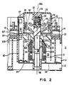
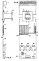
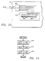
- a recess 52 into which the crossbar 54 of the carrier 42 is disposed and constrained from moving transversely (radially) as shown in Fig. 2, but is free to move or slide longitudinally (axially) of the center line 38A of the aforementioned channel 38.
- Contact bridge 44 is maintained in carrier 42 with the help of a contact spring 56.
- the contact spring 56 compresses to allow continued movement of the carrier 52 towards slug 36 even after the contacts 22-46 and 26-48 have abutted or "made".
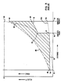
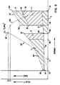
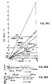
- Fig. 2 and Fig. 3 four superimposed curves are shown for the purpose of depicting the state or the art prior to the present invention.
- plots of force versus distance for a magnetic solenoid such as 31 in Fig. 2, a kickout spring such as 34 shown in Fig. 2, and a contact spring such as 56 shown in Fig. 2 are depicted.
- a superimposed plot 92 of instanteneous velocity versus distance is depicted for an armature such as 40 shown in Fig. 2.
- the independent variable in each case is distance, it could just as well be time as the two variables are closely related for the curves shown in Fig. 3. It is to be understood that the reference to component parts of the contactor 10 of Fig.
- the difference in energy is represented by the area enclosed by the lines which connect the points 74, 88, curve 86, points 90, 84 82, 81 and 74 once again. This energy is wasted or unnecessary energy, and it would be very desirable not to have to produce this energy.
- the second undesirable characteristic or situation is the fact that the armature 80 is accelerating at its maximum and producing its most force of kinetic energy at the instant immediaely before it makes abutting contact with the permanent magent 36.
- a velocity curve 92 which starts at point 72 and ends at point 94 as shown in Fig. 3, represents the velocity of the armature 40 as it accelerates along its axial motion path. Note the change in shape at 80 as the kickout spring 34 is engaged.
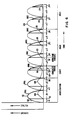
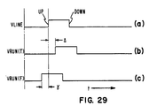
- seal-in or GRAB may occur by allowing coil current to flow for a portion of a current half-wave represented by conduction angles p4, ⁇ 5 and 66, for example, to generate sea;-in or GRAB pulses 120.
- the ACCELERATION, COAST and GRAB operations work on the principle of feed forward voltage control. In the last stage of operation, HOLD, it is recognized that the mechanical system has essentially come to rest but a certain amount of magnetism is nevertheless necessary to keep the armature 40 abutted against the. fixed magnet 36 thus keeping the contacts closed.
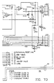
- the overload relay board 60 which includes a connector J101 and connector J102 which are complementary with and connectable to the connector J2 on coil current control board 28 by way of a cable 64.
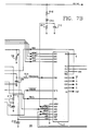
- the previously-mentioned current-to-voltage transducer former 62 may be represented by three transformers 62A, 62B and 62C, respectively for a three-phase electrical system which is controlled by the overload relay board 60.
- One side of each of the secondary windings of these current-to-voltage transducers 62A, 62B and 62C is grounded while the other side is connected to one side of a resistive element R101, R102 and R103, respectively.
- a triple two-channel analog multiplexer/demultiplexer or transmission gate U101 having terminals aOR, bOR and cOR connected to the other sides of resistive elements R101, R102 and R103, respectively.
- the ay, by and cy terminals of gate U101 are connected to ground.
- Terminals ax, bx and cx of gate U101 are all tied together electrically and connected to one side of an integrating capacitor C101 and the anode of a rectifier CR101.
- the + 10V power supply voltage is supplied to the aforementioned amplifier-with-gain U105 and to one side of a resistive element 104, the other side of which is connected to supply power to the aforementioned transmission gates U101 and U102 as well as the anode of a diode CR106, the cathode of which is connected to the + 5 V power supply voltage.
- the + 5 V power supply level VZ on terminal board J102 is also supplied to one side of filter capacitive element C103, the other side of which is grounded and to one main terminal of a potentiometer P102, the other main terminal of which is ground ed.
- the other side of the normally open START pushbutton is connected to the "3" input terminal of the terminal board J1
- the other side of the RESET pushbutton is connected to the reset terminal R of the terminal board J1.
- the aforementioned pushbuttons may be manipulated in a manner well known in the art to provide control information to the coil control board 28 and overload relay board 60.
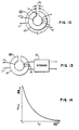
- the cross-sectional area of the core is designated A, and the cross-sectional area of the air gap is designated A2.
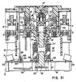
- the output voltage of the transformer is varied by changing the effective length of the air gap I 2 . This can be accomplished by either inserting metallic shims into the air gap 111 as is shown in Figs. 15 and 16, or by moving separate portions of the core structure of the transformer as shown in Fig. 17, to provide a relatively smaller or larger air gap 111. Once the length of the air gap 111 has been chosen, a relatively small current-sensing transformer or transducer is formed which produces an output voltage eo(t) which is generally proportional to the derivative of the input current iL1 in the input winding of the transformer.
- Equation (1) The output voltage eo(t) produced by the secondary winding of the transformer or transducer 62X shown in Fig. 12, for example, is given by Equation (1):
- Voltage V is less than or equal to voltage V2 for the first magnetic reluctance and for values of current I less than or equal to 11.
- the variable but discrete air gap is changeable to provide a second and higher value of air gap reluctance which prevents magnetic saturation of the magnetic core of values of electrical current I less than or equal to 12 where 12 is greater than 11.
- the voltage V remains, less than or equal to V1 for the second value of air gap reluctance and for values of current less than or equal to 12.
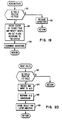
- the LVOLT signal is utilized in the "READVOLTS" algorithm of Fig. 20.
- a decision block 162 asks the question “Is this a positive voltage half cycle?". The question is asked and answered in the same manner associated with the question in decision block 152 associated with Fig. 19. If the answer to the question in decision block 162 is "No", then the algorithm is exited. If the answer is "Yes”, then command block 164 orders the microprocessor to select the AN3 input of the microprocessor U2 to perform an analog-to-digital conversion on the signal there present in correspondence with the command block 162. This information is then stored in the memory locations of the microprocessor U2 accoridng to command block 168 for use in a manner described previously and the algorithm is exited.
- the output voltage V C101 across the integrating capacitor C101 is provided to the buffer amplifier with gain U105 for creating the signal MCUR which is provided to the AN1 input terminal of the microprocessor U2.
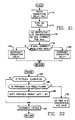
- the microprocessor U2 digitizes the data provided by the signal MCUR in a manner associated with the "RANGE" algorithm of Fig. 22.
- the voltage signal MCUR is provided as a single analog input to an eight-bit five-volt A-to-D (analog-to-digital) converter 200 which is an internal part of the microprocessor U2.
- Equation (1) the output voltage for the transducer as originally defined by Equation (1) may be rewritten in the form shown in Equation (5).
- the output voltage eo(t) is impressed across the resistor R101 for conversion into a charging current iCH for the integrating capacitor C101 according to Equation (6).
- a plot of this expressed in per units (P.U.) is shown in Fig. 25B.
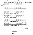
- the A-to-D converter 200 can accept input voltages up to 5 volts positive for producing an 8-bit signal for provision to the first eight locations, 204, of an accumulator or storage device 202 which is located in the memory of the microprocessor U2.
- the maximum five volts input is represented by a decimal number of 256 which corresponds to digital ones in all eight locations of portion 204 of accumulator 202.
- the digitization does not take place for the simple reason that the output of the analog-to-digital converter would be unreliable with such a large analog number on its input.
- the digital number stored in the portion 204 of the accumulator 200 during the previous digitization of the 3.2 volt analog signal is merely shifted one place to the left for each bit in the digital number to provide a new digital number which is equivalent to the decimal number 326.
- the new digital number utilizes a portion of the spill-over member 206 of the accumulator 202 as is clearly shown in Fig. 27.
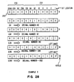
- the "RANGE” algorithm samples at HCYCLE equal “2", "4" and “8” and provides appropriate analog-to-digital conversions to update the portion 204 of the accumulator 202.
- HCYCLE samples "16" and "32” the portion 204 of the accumulator 202 is updated by two successive serial left shifts of the previous information stored in the location 204 rather than by an analog-to-digital conversion. It is clear that an analog-to-digital conversion would have produced an unreliable result for the latter two samples.
- HCYCLE equal "2" .8 volts is digitized producing a digital number equivalent to the decimal number 40.
- the new digital number has a digital 1 in the "256”, “64”, “4" and “2" bit locations of the accumulator 202.
- the new digital number has a decimal equivalent of 652.
- the new digital number has a digital one in the "512" location, "128” location, the "8” bit location and the "4" bit location. This number is then utilized to represent the current measured in the line by way of the overload relay board 60, the value stored in the accumulator 202 will be utilized as described previously for performing useful functions by the contactor or controller 10.
- the nipple or protrusion 336 is provided. This prevents movement of the leg 322 under the influence of the hold pulses but nevertheless reduces the residual magnetism to a point where the operation of the kickout spring 34' is effective.
Landscapes
- Engineering & Computer Science (AREA)
- Power Engineering (AREA)
- Electromagnets (AREA)
- Control Of Electric Motors In General (AREA)
- Measuring Instrument Details And Bridges, And Automatic Balancing Devices (AREA)
- Transformers For Measuring Instruments (AREA)
Applications Claiming Priority (2)
| Application Number | Priority Date | Filing Date | Title |
|---|---|---|---|
| US1642287A | 1987-02-19 | 1987-02-19 | |
| US16422 | 1987-02-19 |
Publications (1)
| Publication Number | Publication Date |
|---|---|
| EP0280444A1 true EP0280444A1 (de) | 1988-08-31 |
Family
ID=21777043
Family Applications (1)
| Application Number | Title | Priority Date | Filing Date |
|---|---|---|---|
| EP88301164A Withdrawn EP0280444A1 (de) | 1987-02-19 | 1988-02-12 | Elektromagnetische Kontaktanordnung mit leichtem, für breite Bereiche geeignetem Stromübersetzer |
Country Status (6)
| Country | Link |
|---|---|
| EP (1) | EP0280444A1 (de) |
| JP (1) | JPS63282666A (de) |
| AU (1) | AU595678B2 (de) |
| BR (1) | BR8800664A (de) |
| CA (1) | CA1317998C (de) |
| MX (1) | MX169715B (de) |
Cited By (3)
| Publication number | Priority date | Publication date | Assignee | Title |
|---|---|---|---|---|
| DE102009015280A1 (de) * | 2009-04-01 | 2010-10-14 | B2Electronic Gmbh | Vorrichtung zur Diagnose von Messobjekten unter Verwendung einer Messspannung |
| DE102010013103A1 (de) * | 2010-03-29 | 2011-09-29 | B2 Electronic Gmbh | Vorrichtung und Verfahren zur Diagnose von Messobjekten unter Verwendung einer Messspannung |
| WO2021043646A1 (de) * | 2019-09-04 | 2021-03-11 | Volkswagen Aktiengesellschaft | Überwachungsvorrichtung, kraftfahrzeug und verfahren zur überwachung einer masseanbindung eines motorblocks mit einer karosserie eines kraftfahrzeugs |
Citations (5)
| Publication number | Priority date | Publication date | Assignee | Title |
|---|---|---|---|---|
| BE389516A (de) * | ||||
| DE856021C (de) * | 1950-11-10 | 1952-11-17 | Siemens Ag | Einrichtung zum Schalten oder Regeln der Spannung fuer Stromverbraucher |
| FR1384805A (fr) * | 1963-11-28 | 1965-01-08 | Applic Electro Thermiques Soc | Inductance variable |
| DE1763092A1 (de) * | 1968-03-14 | 1972-01-05 | Landis & Gyr Ag | Messwandler mit einstellbarem UEbersetzungsverhaeltnis |
| GB1275787A (en) * | 1969-09-04 | 1972-05-24 | Drake Transformers Ltd | Improvements in and relating to variable inductances |
Family Cites Families (3)
| Publication number | Priority date | Publication date | Assignee | Title |
|---|---|---|---|---|
| US3197721A (en) * | 1963-07-01 | 1965-07-27 | Sperry Rand Corp | Toroidal apparatus with winding surrounding both core and gap wherein permeable material is variably positioned |
| JPS5089075A (de) * | 1973-12-10 | 1975-07-17 | ||
| JPS5173472A (ja) * | 1974-12-21 | 1976-06-25 | Omron Tateisi Electronics Co | Denryukenshutsusochi |
-
1988
- 1988-02-04 AU AU11297/88A patent/AU595678B2/en not_active Ceased
- 1988-02-12 EP EP88301164A patent/EP0280444A1/de not_active Withdrawn
- 1988-02-17 CA CA000559151A patent/CA1317998C/en not_active Expired - Fee Related
- 1988-02-18 BR BR8800664A patent/BR8800664A/pt not_active IP Right Cessation
- 1988-02-18 MX MX1046288A patent/MX169715B/es unknown
- 1988-02-19 JP JP63037360A patent/JPS63282666A/ja active Pending
Patent Citations (5)
| Publication number | Priority date | Publication date | Assignee | Title |
|---|---|---|---|---|
| BE389516A (de) * | ||||
| DE856021C (de) * | 1950-11-10 | 1952-11-17 | Siemens Ag | Einrichtung zum Schalten oder Regeln der Spannung fuer Stromverbraucher |
| FR1384805A (fr) * | 1963-11-28 | 1965-01-08 | Applic Electro Thermiques Soc | Inductance variable |
| DE1763092A1 (de) * | 1968-03-14 | 1972-01-05 | Landis & Gyr Ag | Messwandler mit einstellbarem UEbersetzungsverhaeltnis |
| GB1275787A (en) * | 1969-09-04 | 1972-05-24 | Drake Transformers Ltd | Improvements in and relating to variable inductances |
Non-Patent Citations (2)
| Title |
|---|
| PATENT ABSTRACTS OF JAPAN, vol. 10, no. 150 (E-408)[2207], 31st May 1986; & JP-A-61 008 910 (HITACHI DENSEN K.K.) 16-01-1986 * |
| PATENT ABSTRACTS OF JAPAN, vol. 5, no. 7 (E-41)[679], 17th January 1981; & JP-A-55 136 499 (TOKYO SHIBAURA DENKI K.K.) 24-10-1980 * |
Cited By (4)
| Publication number | Priority date | Publication date | Assignee | Title |
|---|---|---|---|---|
| DE102009015280A1 (de) * | 2009-04-01 | 2010-10-14 | B2Electronic Gmbh | Vorrichtung zur Diagnose von Messobjekten unter Verwendung einer Messspannung |
| DE102010013103A1 (de) * | 2010-03-29 | 2011-09-29 | B2 Electronic Gmbh | Vorrichtung und Verfahren zur Diagnose von Messobjekten unter Verwendung einer Messspannung |
| DE102010013103B4 (de) * | 2010-03-29 | 2015-06-11 | B2 Electronic Gmbh | Vorrichtung und Verfahren zur Diagnose von Messobjekten unter Verwendung einer Messspannung |
| WO2021043646A1 (de) * | 2019-09-04 | 2021-03-11 | Volkswagen Aktiengesellschaft | Überwachungsvorrichtung, kraftfahrzeug und verfahren zur überwachung einer masseanbindung eines motorblocks mit einer karosserie eines kraftfahrzeugs |
Also Published As
| Publication number | Publication date |
|---|---|
| CA1317998C (en) | 1993-05-18 |
| AU1129788A (en) | 1988-09-01 |
| MX169715B (es) | 1993-07-20 |
| JPS63282666A (ja) | 1988-11-18 |
| BR8800664A (pt) | 1988-10-04 |
| AU595678B2 (en) | 1990-04-05 |
Similar Documents
| Publication | Publication Date | Title |
|---|---|---|
| US4893102A (en) | Electromagnetic contactor with energy balanced closing system | |
| EP0279593B1 (de) | Elektromagnetisches Schütz mit Steuerkreis für die Versorgung der Beschleunigungs-, Landungs- und Greiffunktion | |
| EP0279597B1 (de) | Elektromagnetisches Schütz mit reduziertem Lärm des magnetischen Ankers | |
| US4980794A (en) | Electromagnetic contactor with lightweight wide range current transducer with sintered powdered metal core | |
| US4833565A (en) | Electromagnetic contactor with algorithm controlled closing system | |
| US4757420A (en) | Electromagnetic contactor with wide range overload current relay board utilizing left shifting and method | |
| EP0279595B1 (de) | Elektromagnetischer Schutz mit stromgeregelter elektromagnetischer Wicklung für das Zusammenhalten der Kontakte | |
| US4728810A (en) | Electromagnetic contactor with discriminator for determining when an input control signal is true or false and method | |
| EP0279592B1 (de) | Elektromagnetisches Schütz mit energetisch ausbalancierter Schliessfunktion | |
| US4748343A (en) | Electromagnetic contactor with universal control | |
| AU611126B2 (en) | Electromagnetic contactor with lightweight wide range current transducer with sintered powdered metal core | |
| EP0280444A1 (de) | Elektromagnetische Kontaktanordnung mit leichtem, für breite Bereiche geeignetem Stromübersetzer | |
| GB2201296A (en) | Electromagnetic contactor |
Legal Events
| Date | Code | Title | Description |
|---|---|---|---|
| PUAI | Public reference made under article 153(3) epc to a published international application that has entered the european phase |
Free format text: ORIGINAL CODE: 0009012 |
|
| AK | Designated contracting states |
Kind code of ref document: A1 Designated state(s): DE FR GB IT SE |
|
| 17P | Request for examination filed |
Effective date: 19890110 |
|
| 17Q | First examination report despatched |
Effective date: 19910510 |
|
| STAA | Information on the status of an ep patent application or granted ep patent |
Free format text: STATUS: THE APPLICATION IS DEEMED TO BE WITHDRAWN |
|
| 18D | Application deemed to be withdrawn |
Effective date: 19911122 |