EP0280457A2 - Vorrichtung zum Anbringen von starren Abstandshaltern in Laufwagen für vertikalen Store - Google Patents
Vorrichtung zum Anbringen von starren Abstandshaltern in Laufwagen für vertikalen Store Download PDFInfo
- Publication number
- EP0280457A2 EP0280457A2 EP88301272A EP88301272A EP0280457A2 EP 0280457 A2 EP0280457 A2 EP 0280457A2 EP 88301272 A EP88301272 A EP 88301272A EP 88301272 A EP88301272 A EP 88301272A EP 0280457 A2 EP0280457 A2 EP 0280457A2
- Authority
- EP
- European Patent Office
- Prior art keywords
- spacer
- holding station
- traveller
- holding
- travellers
- Prior art date
- Legal status (The legal status is an assumption and is not a legal conclusion. Google has not performed a legal analysis and makes no representation as to the accuracy of the status listed.)
- Granted
Links
Images

Classifications
-
- E—FIXED CONSTRUCTIONS
- E06—DOORS, WINDOWS, SHUTTERS, OR ROLLER BLINDS IN GENERAL; LADDERS
- E06B—FIXED OR MOVABLE CLOSURES FOR OPENINGS IN BUILDINGS, VEHICLES, FENCES OR LIKE ENCLOSURES IN GENERAL, e.g. DOORS, WINDOWS, BLINDS, GATES
- E06B9/00—Screening or protective devices for wall or similar openings, with or without operating or securing mechanisms; Closures of similar construction
- E06B9/24—Screens or other constructions affording protection against light, especially against sunshine; Similar screens for privacy or appearance; Slat blinds
- E06B9/26—Lamellar or like blinds, e.g. venetian blinds
- E06B9/266—Devices or accessories for making or mounting lamellar blinds or parts thereof
-
- Y—GENERAL TAGGING OF NEW TECHNOLOGICAL DEVELOPMENTS; GENERAL TAGGING OF CROSS-SECTIONAL TECHNOLOGIES SPANNING OVER SEVERAL SECTIONS OF THE IPC; TECHNICAL SUBJECTS COVERED BY FORMER USPC CROSS-REFERENCE ART COLLECTIONS [XRACs] AND DIGESTS
- Y10—TECHNICAL SUBJECTS COVERED BY FORMER USPC
- Y10T—TECHNICAL SUBJECTS COVERED BY FORMER US CLASSIFICATION
- Y10T29/00—Metal working
- Y10T29/39—Venetian blind assembling
-
- Y—GENERAL TAGGING OF NEW TECHNOLOGICAL DEVELOPMENTS; GENERAL TAGGING OF CROSS-SECTIONAL TECHNOLOGIES SPANNING OVER SEVERAL SECTIONS OF THE IPC; TECHNICAL SUBJECTS COVERED BY FORMER USPC CROSS-REFERENCE ART COLLECTIONS [XRACs] AND DIGESTS
- Y10—TECHNICAL SUBJECTS COVERED BY FORMER USPC
- Y10T—TECHNICAL SUBJECTS COVERED BY FORMER US CLASSIFICATION
- Y10T29/00—Metal working
- Y10T29/53—Means to assemble or disassemble
- Y10T29/53313—Means to interrelatedly feed plural work parts from plural sources without manual intervention
-
- Y—GENERAL TAGGING OF NEW TECHNOLOGICAL DEVELOPMENTS; GENERAL TAGGING OF CROSS-SECTIONAL TECHNOLOGIES SPANNING OVER SEVERAL SECTIONS OF THE IPC; TECHNICAL SUBJECTS COVERED BY FORMER USPC CROSS-REFERENCE ART COLLECTIONS [XRACs] AND DIGESTS
- Y10—TECHNICAL SUBJECTS COVERED BY FORMER USPC
- Y10T—TECHNICAL SUBJECTS COVERED BY FORMER US CLASSIFICATION
- Y10T29/00—Metal working
- Y10T29/53—Means to assemble or disassemble
- Y10T29/53313—Means to interrelatedly feed plural work parts from plural sources without manual intervention
- Y10T29/53378—Means to interrelatedly feed plural work parts from plural sources without manual intervention including converging conveyors
-
- Y—GENERAL TAGGING OF NEW TECHNOLOGICAL DEVELOPMENTS; GENERAL TAGGING OF CROSS-SECTIONAL TECHNOLOGIES SPANNING OVER SEVERAL SECTIONS OF THE IPC; TECHNICAL SUBJECTS COVERED BY FORMER USPC CROSS-REFERENCE ART COLLECTIONS [XRACs] AND DIGESTS
- Y10—TECHNICAL SUBJECTS COVERED BY FORMER USPC
- Y10T—TECHNICAL SUBJECTS COVERED BY FORMER US CLASSIFICATION
- Y10T29/00—Metal working
- Y10T29/53—Means to assemble or disassemble
- Y10T29/53313—Means to interrelatedly feed plural work parts from plural sources without manual intervention
- Y10T29/53383—Means to interrelatedly feed plural work parts from plural sources without manual intervention and means to fasten work parts together
- Y10T29/53396—Means to interrelatedly feed plural work parts from plural sources without manual intervention and means to fasten work parts together by friction fit
-
- Y—GENERAL TAGGING OF NEW TECHNOLOGICAL DEVELOPMENTS; GENERAL TAGGING OF CROSS-SECTIONAL TECHNOLOGIES SPANNING OVER SEVERAL SECTIONS OF THE IPC; TECHNICAL SUBJECTS COVERED BY FORMER USPC CROSS-REFERENCE ART COLLECTIONS [XRACs] AND DIGESTS
- Y10—TECHNICAL SUBJECTS COVERED BY FORMER USPC
- Y10T—TECHNICAL SUBJECTS COVERED BY FORMER US CLASSIFICATION
- Y10T29/00—Metal working
- Y10T29/53—Means to assemble or disassemble
- Y10T29/53478—Means to assemble or disassemble with magazine supply
-
- Y—GENERAL TAGGING OF NEW TECHNOLOGICAL DEVELOPMENTS; GENERAL TAGGING OF CROSS-SECTIONAL TECHNOLOGIES SPANNING OVER SEVERAL SECTIONS OF THE IPC; TECHNICAL SUBJECTS COVERED BY FORMER USPC CROSS-REFERENCE ART COLLECTIONS [XRACs] AND DIGESTS
- Y10—TECHNICAL SUBJECTS COVERED BY FORMER USPC
- Y10T—TECHNICAL SUBJECTS COVERED BY FORMER US CLASSIFICATION
- Y10T29/00—Metal working
- Y10T29/53—Means to assemble or disassemble
- Y10T29/53478—Means to assemble or disassemble with magazine supply
- Y10T29/53483—Means to assemble or disassemble with magazine supply and magnetic work-holder or positioner
-
- Y—GENERAL TAGGING OF NEW TECHNOLOGICAL DEVELOPMENTS; GENERAL TAGGING OF CROSS-SECTIONAL TECHNOLOGIES SPANNING OVER SEVERAL SECTIONS OF THE IPC; TECHNICAL SUBJECTS COVERED BY FORMER USPC CROSS-REFERENCE ART COLLECTIONS [XRACs] AND DIGESTS
- Y10—TECHNICAL SUBJECTS COVERED BY FORMER USPC
- Y10T—TECHNICAL SUBJECTS COVERED BY FORMER US CLASSIFICATION
- Y10T29/00—Metal working
- Y10T29/53—Means to assemble or disassemble
- Y10T29/53539—Means to assemble or disassemble including work conveyor
- Y10T29/53543—Means to assemble or disassemble including work conveyor including transporting track
Definitions
- the present invention relates to apparatus for feeding a plurality of rigid, ferro-magnetic metallic elongate spacers, one into each of a plurality of travellers for a vertical blind.
- apparatus for feeding a plurality of rigid, ferro-magnetic metallic, elongate prefabricated spacers, one into each of a plurality of travellers for a vertical blind, said apparatus comprising a holding station, a retractable holding member in said station, means for feeding a single traveller into said holding station to be retained by said holding member, a linear guide for guiding said elongate spacers to said holding station in a lengthwise direction, a first feed mechanism for feeding said spacers individually and separately along said guide to a position with the leading edge of the spacer adjacent said holding station, a second feed mechanism for pushing a spacer, so positioned, positively into and through a co-operating slot in a traveller held in said holding station by said holding member and a discharge member for discharging a traveller and its associated spacer from said holding station, when said holding member has been retracted, in a direction parallel to the length of the associated spacer and away from said guide.
- Such an apparatus can feed the ferro-magnetic metallic elongate spacers one into each of the plurality of travellers for a vertical blind in a fully automatic manner without there being any real need for manual intervention other than providing supervision of the operation.
- the first feed mechanism preferably includes a plurality of magnetic rollers rotatable about axes perpendicular to the linear guide and spaced therealong. These magnetic rollers can cause the ferro-magnetic metallic elongate spacers to be taken up and moved accurately forwardly by the correct amount, to a position in which the leading edge of the leading spacer is immediately adjacent the holding station and a traveller positioned therein.
- the second feed mechanism which may, for example, comprise a fluid pressure operated piston and cylinder arrangement carrying a pusher finger movable along the guide by operation of the piston and cylinder arrangement, can then cause the spacer to be forced into the housing so that it passes through the co-operating slot in the traveller housing.
- the finger is pivotally mounted on the piston rod of the fluid pressure operated piston cylinder arrangement so that when the piston is retracted, it can then take up a position to operate on a subsequent spacer, the finger can pivot upwardly and readily pass over the next spacer which by this time will have been located close to the holding station.
- the means for feeding travellers advantageously comprise a system for feeding travellers tranversely to the longitudinal direction of the linear guide and equally the holding member is preferably retracted by movement in a direction transverse to the longitudinal direction of the linear guide.
- the holding member itself actually forms the means for feeding the travellers to the holding station.
- the discharge member comprises a further fluid pressure operated piston and cylinder arrangement which is mounted adjacent and substantially parallel to the linear guide and this can co-operate with the discharge guide positioned to receive several of the travellers and associated spacers as they are moved by the discharge member from the holding station.
- a magnetic catcher element is positioned adjacent the holding station to catch the free end of the spacer after it has been pushed through the associated slot of a traveller, releasing said spacer as the associated traveller is discharged from the holding station.
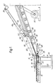
- the apparatus illustrated includes a base 10 carrying first and second support pillars 12 and 14.
- the first support pillar carries a horizontal frame 15 which supports a holding station 16.
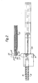
- feeding means indicated by the general reference numeral 18 include a magazine 20 carrying several traveller housings 22 which are urged to the left by means, such as a spring, pneumatic cylinder or the like (not shown).
- a reciprocable fork 24 includes a retractable holding member 25 which is movable to engage an end traveller housing 26 at the left end of the magazine 20, as seen in Figure 2, and move this along a transverse axis 27 into the holding station 16.
- the fork can also be operated by a pneumatic piston and cylinder arrangement (not shown).
- a first feed mechanism 28 includes a linear guide in the form of a ramp 30 associated with which are several magnetic rollers 32 positioned in recesses 34 and mounted for rotation about horizontal axes 36.
- the rollers 32 can be rotated in a counter-clockwise direction by a motor 37 and an associated chain system not illustrated in detail.
- the lower end of the ramp 30 includes a groove 38 into which the lowermost roller 32 and a non-magnetic further roller 33 project.
- the second feed mechanism 40 includes a pneumatic cylinder 42 having a piston, a piston rod 44 of which carries a pusher finger 46 via a pivotal connection 48 which allows the finger to pivot from the position shown in a clockwise direction to a limited extent about a horizontal axis.
- a pneumatic cylinder 42 is mounted via a horizontal axis pivot 50 on a bracket 52.
- each traveller housing 22 is provided with a pair of guide rollers 54 and the upper zone of the housing includes a first bridge 56 and a second bridge 58 under which are formed slots 59 and 60.
- a spacer 62 having an upturned leading end 64 and a downturned rear stop 66.
- Each spacer is prefabricated to the exact length required. It is this arrangement that the apparatus of the present invention is designed to assemble.
- a discharge member 68 Mounted below the ramp 30, at the lower end thereof, is a discharge member 68 having a horizontal axis ending in the same plane as the axis of the ramp 30 and the second feed mechanism cylinder 42.
- a discharge head 72 mounted on the piston rod 73 of the cylinder 70.
- a guide rail 74 carried on a guide rail support 76 mounted on the second support pillar 14.
- a pair of spaced discharge guides 78 spaced apart from one another by a distance so that the guide rollers 54 of the traveller housing 22 can run along these guide rails 78.
- a magnetic catcher element 80 is mounted below the frame 15 adjacent the holding station 16.
- a supply of traveller housings 22 are mounted in the magazine 20 and urged to the left by the means not shown.
- the feed mechanism 18 is then operated so that the end housing 26 is accommodated in the holding member 25 and continued movement of the fork 24 along the axis 27 urges the housing into the holding station, that is to say so that it lies in the vertical plane including the axes of the discharge member 68, of the first feed mechanism 28 and the second feed mechanism 40.
- the lowermost spacer 62 is positioned with its leading edge 64 adjacent the thus positioned traveller housing. This is achieved by the spacer being forced downwardly by the magnetic rollers 32 translating these spacers themselves in spaced relation towards the bottom. Having left the lowermost magnetic roller 32, continued movement of the spacer is assisted by the non-magnetic roller 33.
- the second feed mechanism 42 is then actuated and the pusher finger 46 engages the downturned rear stop 66 of this lowermost spacer and continued operation of the cylinder causes the finger to push the leading edge of the spacer into the slot 60 under the first bridge and then into the slot 59 under the second bridge.
- the spacer is then guided through guiding fork 24 to the preceeding traveller housing.
- the spacer is pushed into slot 59 under the first bridge 56 of said traveller housing and over the second bridge 58.
- fork 24 is retracted and the discharge cylinder 70 is actuated and the discharge head 72 pushes the housing 22 and its associated spacer to the left along the guide rails 74.
- the magnetic catcher 80 catches the leading edge of the inserted spacer.
- the operation is then repeated as many times as is necessary and each time the discharge cylinder is operated the housings are pushed to the left so that their rollers 54 move along the guide rail 78.
- the leading edge of the second and subsequent spacers 62 is pivoted under the first bridge 56 of the previous housing, above the spacer already inserted therein, and then over the second bridge 58, before being caught by the magnetic catcher 80, which prevents this from becoming entangled with the previously assembled traveller housings and spacers.
- the housings are shown slightly spaced from one another for the sake of clarity. In practice they would be rather closer together as they are discharged along the rail 78.
- the operation is stopped when the desired number of travellers and spacers have been assembled to form sufficient for a given blind.
- the operation is then recommenced when the travellers for a new blind are to be assembled.
Landscapes
- Structural Engineering (AREA)
- Engineering & Computer Science (AREA)
- Architecture (AREA)
- Civil Engineering (AREA)
- Automatic Assembly (AREA)
- Operating, Guiding And Securing Of Roll- Type Closing Members (AREA)
- Tents Or Canopies (AREA)
- Blinds (AREA)
- Replacement Of Web Rolls (AREA)
- Control Of Conveyors (AREA)
- Tunnel Furnaces (AREA)
- Controlling Rewinding, Feeding, Winding, Or Abnormalities Of Webs (AREA)
- Golf Clubs (AREA)
- Forklifts And Lifting Vehicles (AREA)
- Chair Legs, Seat Parts, And Backrests (AREA)
- Cable Accessories (AREA)
- Ticket-Dispensing Machines (AREA)
- Analysing Materials By The Use Of Radiation (AREA)
- Insulating Bodies (AREA)
- Handcart (AREA)
- Unwinding Of Filamentary Materials (AREA)
Priority Applications (1)
| Application Number | Priority Date | Filing Date | Title |
|---|---|---|---|
| AT88301272T ATE59692T1 (de) | 1987-02-27 | 1988-02-16 | Vorrichtung zum anbringen von starren abstandshaltern in laufwagen fuer vertikalen store. |
Applications Claiming Priority (2)
| Application Number | Priority Date | Filing Date | Title |
|---|---|---|---|
| GB8704649 | 1987-02-27 | ||
| GB8704649A GB2201710B (en) | 1987-02-27 | 1987-02-27 | Apparatus for feeding rigid spacers into travellers for a vertical blind |
Publications (3)
| Publication Number | Publication Date |
|---|---|
| EP0280457A2 true EP0280457A2 (de) | 1988-08-31 |
| EP0280457A3 EP0280457A3 (en) | 1989-04-05 |
| EP0280457B1 EP0280457B1 (de) | 1991-01-02 |
Family
ID=10613060
Family Applications (1)
| Application Number | Title | Priority Date | Filing Date |
|---|---|---|---|
| EP88301272A Expired - Lifetime EP0280457B1 (de) | 1987-02-27 | 1988-02-16 | Vorrichtung zum Anbringen von starren Abstandshaltern in Laufwagen für vertikalen Store |
Country Status (7)
| Country | Link |
|---|---|
| US (1) | US4835848A (de) |
| EP (1) | EP0280457B1 (de) |
| AT (1) | ATE59692T1 (de) |
| DE (1) | DE3861332D1 (de) |
| DK (1) | DK104788A (de) |
| ES (1) | ES2020600B3 (de) |
| GB (1) | GB2201710B (de) |
Cited By (1)
| Publication number | Priority date | Publication date | Assignee | Title |
|---|---|---|---|---|
| EP0516003A3 (en) * | 1991-05-25 | 1993-02-17 | Klaus-D. Dipl.-Ing. Wecker | Method and apparatus for the production of interconnected spacers for vertical blinds |
Families Citing this family (4)
| Publication number | Priority date | Publication date | Assignee | Title |
|---|---|---|---|---|
| US5594985A (en) * | 1995-05-08 | 1997-01-21 | Texas Instruments Incorporated | End pin extractor for semiconductor storage tube |
| US6321821B1 (en) * | 1999-12-30 | 2001-11-27 | Benthin Aktiengesellschaft | Traveler for a vertical blind |
| US8551762B2 (en) * | 2009-07-07 | 2013-10-08 | Nch Corporation | System and apparatus for feeding, solubilizing, growing and discharging a biological material |
| US8881364B2 (en) * | 2010-12-03 | 2014-11-11 | Btm Corporation | Pierce nut insertion tool |
Family Cites Families (6)
| Publication number | Priority date | Publication date | Assignee | Title |
|---|---|---|---|---|
| US2917810A (en) * | 1956-11-13 | 1959-12-22 | Elmo S Wilson | Venetian blind assembly device |
| US3281914A (en) * | 1964-08-21 | 1966-11-01 | Products Engineering Co | Method and apparatus for assembling venetian blinds |
| BE731284A (de) * | 1969-02-19 | 1969-09-15 | ||
| SE361915B (de) * | 1972-04-12 | 1973-11-19 | S A Nilsson | |
| GB2124283B (en) * | 1982-07-16 | 1987-04-23 | Hunter Douglas Ind Bv | Slat feeding apparatus for venetian blind assembling machine |
| SE440933B (sv) * | 1984-01-10 | 1985-08-26 | Gustav Kohler | Vexlingsanordning vid en maskin for tillverkning av persienner |
-
1987
- 1987-02-27 GB GB8704649A patent/GB2201710B/en not_active Expired - Fee Related
-
1988
- 1988-02-16 ES ES88301272T patent/ES2020600B3/es not_active Expired - Lifetime
- 1988-02-16 DE DE8888301272T patent/DE3861332D1/de not_active Expired - Fee Related
- 1988-02-16 AT AT88301272T patent/ATE59692T1/de active
- 1988-02-16 EP EP88301272A patent/EP0280457B1/de not_active Expired - Lifetime
- 1988-02-25 US US07/160,549 patent/US4835848A/en not_active Expired - Fee Related
- 1988-02-26 DK DK104788A patent/DK104788A/da not_active Application Discontinuation
Cited By (1)
| Publication number | Priority date | Publication date | Assignee | Title |
|---|---|---|---|---|
| EP0516003A3 (en) * | 1991-05-25 | 1993-02-17 | Klaus-D. Dipl.-Ing. Wecker | Method and apparatus for the production of interconnected spacers for vertical blinds |
Also Published As
| Publication number | Publication date |
|---|---|
| DE3861332D1 (de) | 1991-02-07 |
| US4835848A (en) | 1989-06-06 |
| DK104788A (da) | 1988-08-28 |
| GB8704649D0 (en) | 1987-04-01 |
| GB2201710A (en) | 1988-09-07 |
| EP0280457B1 (de) | 1991-01-02 |
| ES2020600B3 (es) | 1991-08-16 |
| EP0280457A3 (en) | 1989-04-05 |
| DK104788D0 (da) | 1988-02-26 |
| GB2201710B (en) | 1990-10-17 |
| ATE59692T1 (de) | 1991-01-15 |
Similar Documents
| Publication | Publication Date | Title |
|---|---|---|
| EP0222344B1 (de) | Vorrichtung zum Prüfen und Sortieren von elektronischen Bauelementen | |
| US6003218A (en) | Apparatus for cutting and assembling slats for window blind units | |
| DE3637561C2 (de) | ||
| US5020575A (en) | Method and installation for feeding longitudinal elements to a welding machine for grates or gratings | |
| EP2689904B1 (de) | Verfahren zum maschinellen, sequentiellen Einsetzen von separaten Verbindern in Nuten von plattenförmigen Baupaneelen sowie Vorrichtung zur Durchführung des Verfahrens | |
| EP0143960B1 (de) | Vorrichtung zum Richten und Ablängen von Draht | |
| US4612700A (en) | Component insertion apparatus | |
| EP0037202B1 (de) | Verfahren und Anordnung zur Herstellung von mit Verdrahtung versehenen elektrischen Verbindern | |
| EP0280457B1 (de) | Vorrichtung zum Anbringen von starren Abstandshaltern in Laufwagen für vertikalen Store | |
| EP0080230A1 (de) | Vorrichtung zum automatischen Schneiden einer Metallplatte in mehrere Stücke unterschiedlicher Abmessungen | |
| DE3141784C2 (de) | Vorrichtung zum Zu- und Wegführen von Statoren elektrischer Maschinen | |
| US4122594A (en) | Method for engaging a slider automatically on a slide fastener chain | |
| EP0315413B1 (de) | Apparat und Verfahren zum Buchbinden | |
| EP0133759B1 (de) | Einrichtung und Verfahren zur Montage von Lamellen für Jalousien | |
| US4131993A (en) | Means for engaging a slider automatically on a slide fastener chain | |
| EP0405064A1 (de) | Vorrichtung zum Vereinzeln und/oder Entnehmen von Profilstäben | |
| US4323336A (en) | Inserting sticks into confections | |
| US3469608A (en) | Coil spring positioning device | |
| US1971963A (en) | Pin ticketing machine | |
| US2658631A (en) | Apparatus for feeding cleats to boxmaking machines | |
| DE3821432B4 (de) | Vorrichtung zur Verwendung bei einem elektrischen Verbinder | |
| DE2610475C3 (de) | Vorrichtung zum einzelweisen Entnehmen und Abführen von Platten | |
| US4098154A (en) | Safety end of run feeder | |
| DE19916346C2 (de) | Vorrichtung zum Zuführen elektronischer Bauteile | |
| DE2640172A1 (de) | Einrichtung zum montieren von waescheklammern |
Legal Events
| Date | Code | Title | Description |
|---|---|---|---|
| PUAI | Public reference made under article 153(3) epc to a published international application that has entered the european phase |
Free format text: ORIGINAL CODE: 0009012 |
|
| AK | Designated contracting states |
Kind code of ref document: A2 Designated state(s): AT BE CH DE ES FR GB IT LI NL SE |
|
| PUAL | Search report despatched |
Free format text: ORIGINAL CODE: 0009013 |
|
| AK | Designated contracting states |
Kind code of ref document: A3 Designated state(s): AT BE CH DE ES FR GB IT LI NL SE |
|
| 17P | Request for examination filed |
Effective date: 19890925 |
|
| 17Q | First examination report despatched |
Effective date: 19900412 |
|
| GRAA | (expected) grant |
Free format text: ORIGINAL CODE: 0009210 |
|
| AK | Designated contracting states |
Kind code of ref document: B1 Designated state(s): AT BE CH DE ES FR GB IT LI NL SE |
|
| PG25 | Lapsed in a contracting state [announced via postgrant information from national office to epo] |
Ref country code: AT Effective date: 19910102 Ref country code: CH Effective date: 19910102 Ref country code: LI Effective date: 19910102 Ref country code: BE Effective date: 19910102 |
|
| REF | Corresponds to: |
Ref document number: 59692 Country of ref document: AT Date of ref document: 19910115 Kind code of ref document: T |
|
| REF | Corresponds to: |
Ref document number: 3861332 Country of ref document: DE Date of ref document: 19910207 |
|
| PGFP | Annual fee paid to national office [announced via postgrant information from national office to epo] |
Ref country code: SE Payment date: 19910211 Year of fee payment: 4 |
|
| PGFP | Annual fee paid to national office [announced via postgrant information from national office to epo] |
Ref country code: FR Payment date: 19910212 Year of fee payment: 4 |
|
| PGFP | Annual fee paid to national office [announced via postgrant information from national office to epo] |
Ref country code: ES Payment date: 19910215 Year of fee payment: 4 |
|
| PGFP | Annual fee paid to national office [announced via postgrant information from national office to epo] |
Ref country code: NL Payment date: 19910228 Year of fee payment: 4 |
|
| ET | Fr: translation filed | ||
| ITF | It: translation for a ep patent filed | ||
| PGFP | Annual fee paid to national office [announced via postgrant information from national office to epo] |
Ref country code: DE Payment date: 19910328 Year of fee payment: 4 |
|
| REG | Reference to a national code |
Ref country code: CH Ref legal event code: PL |
|
| PLBE | No opposition filed within time limit |
Free format text: ORIGINAL CODE: 0009261 |
|
| STAA | Information on the status of an ep patent application or granted ep patent |
Free format text: STATUS: NO OPPOSITION FILED WITHIN TIME LIMIT |
|
| 26N | No opposition filed | ||
| PG25 | Lapsed in a contracting state [announced via postgrant information from national office to epo] |
Ref country code: SE Effective date: 19920217 Ref country code: ES Free format text: LAPSE BECAUSE OF NON-PAYMENT OF DUE FEES Effective date: 19920217 |
|
| PG25 | Lapsed in a contracting state [announced via postgrant information from national office to epo] |
Ref country code: NL Effective date: 19920901 |
|
| NLV4 | Nl: lapsed or anulled due to non-payment of the annual fee | ||
| PG25 | Lapsed in a contracting state [announced via postgrant information from national office to epo] |
Ref country code: FR Effective date: 19921030 |
|
| PG25 | Lapsed in a contracting state [announced via postgrant information from national office to epo] |
Ref country code: DE Effective date: 19921103 |
|
| REG | Reference to a national code |
Ref country code: FR Ref legal event code: ST |
|
| EUG | Se: european patent has lapsed |
Ref document number: 88301272.6 Effective date: 19920904 |
|
| REG | Reference to a national code |
Ref country code: ES Ref legal event code: FD2A Effective date: 19990503 |
|
| PG25 | Lapsed in a contracting state [announced via postgrant information from national office to epo] |
Ref country code: IT Free format text: LAPSE BECAUSE OF NON-PAYMENT OF DUE FEES;WARNING: LAPSES OF ITALIAN PATENTS WITH EFFECTIVE DATE BEFORE 2007 MAY HAVE OCCURRED AT ANY TIME BEFORE 2007. THE CORRECT EFFECTIVE DATE MAY BE DIFFERENT FROM THE ONE RECORDED. Effective date: 20050216 |
|
| PG25 | Lapsed in a contracting state [announced via postgrant information from national office to epo] |
Ref country code: GB Free format text: LAPSE BECAUSE OF NON-PAYMENT OF DUE FEES Effective date: 19910102 |
|
| REG | Reference to a national code |
Ref country code: GB Ref legal event code: PE20 Expiry date: 20060511 |