EP0280483A1 - Dispositif de dressage - Google Patents
Dispositif de dressage Download PDFInfo
- Publication number
- EP0280483A1 EP0280483A1 EP88301460A EP88301460A EP0280483A1 EP 0280483 A1 EP0280483 A1 EP 0280483A1 EP 88301460 A EP88301460 A EP 88301460A EP 88301460 A EP88301460 A EP 88301460A EP 0280483 A1 EP0280483 A1 EP 0280483A1
- Authority
- EP
- European Patent Office
- Prior art keywords
- dressing
- grinding
- unit
- machine
- tool assembly
- Prior art date
- Legal status (The legal status is an assumption and is not a legal conclusion. Google has not performed a legal analysis and makes no representation as to the accuracy of the status listed.)
- Withdrawn
Links
- 239000012530 fluid Substances 0.000 claims description 3
- 229910003460 diamond Inorganic materials 0.000 description 8
- 239000010432 diamond Substances 0.000 description 8
- 230000000717 retained effect Effects 0.000 description 3
- XWROSHJVVFETLV-UHFFFAOYSA-N [B+3].[O-][N+]([O-])=O.[O-][N+]([O-])=O.[O-][N+]([O-])=O Chemical compound [B+3].[O-][N+]([O-])=O.[O-][N+]([O-])=O.[O-][N+]([O-])=O XWROSHJVVFETLV-UHFFFAOYSA-N 0.000 description 1
- 238000010276 construction Methods 0.000 description 1
- 230000001771 impaired effect Effects 0.000 description 1
- 238000003754 machining Methods 0.000 description 1
- 238000012544 monitoring process Methods 0.000 description 1
- HBMJWWWQQXIZIP-UHFFFAOYSA-N silicon carbide Chemical compound [Si+]#[C-] HBMJWWWQQXIZIP-UHFFFAOYSA-N 0.000 description 1
- 229910010271 silicon carbide Inorganic materials 0.000 description 1
Images

Classifications
-
- B—PERFORMING OPERATIONS; TRANSPORTING
- B24—GRINDING; POLISHING
- B24B—MACHINES, DEVICES, OR PROCESSES FOR GRINDING OR POLISHING; DRESSING OR CONDITIONING OF ABRADING SURFACES; FEEDING OF GRINDING, POLISHING, OR LAPPING AGENTS
- B24B53/00—Devices or means for dressing or conditioning abrasive surfaces
- B24B53/12—Dressing tools; Holders therefor
Definitions
- the invention relates to a dressing unit and is particularly, but not exclusively, concerned with a dressing unit for dressing a grinding wheel on a grinding machine.
- a grinding wheel usually made of aluminimum oxide, silicon carbide or boron nitrate, is subject to wear glazing and/or loading. These factors will either impair the grinding wheel's ability to grind a desired profile and/or its cutting efficiency.
- the grinding wheel is dressed so as to restore the wheel profile and wheel surface condition.
- the grinding wheel may be dressed to provide a fresh profile.
- Wheel dressing on a surface grinding machine is normally effected using a diamond tipped dressing tool.
- the dressing tool is mounted on a magnetic chuck of the surface grinding machine.
- the dressing tool is removed from the magnetic chuck and usually stored in a tool cupboard.
- a dressing jig is available which can be mounted at a fixed position adjacent one end of the machine table.
- the jig consists of a plurality of fixed blocks to enable at least one dressing tool to be adjustably positioned.
- One disadvantage of the jig is that an operator must ensure that the dressing tool or tools are correctly positioned prior to commencing an automated wheel dressing operation.
- a further disadvantage is that the dressing tools must be located away from a normal operating region of the grinding wheel; otherwise accidental fouling of the dressing tools by the grinding wheel may result.
- a dressing unit comprising a member one end of which is adapted to be mounted relative to a part of a grinding machine at which relative movement between the part and a grinding wheel of the machine can be effected, and the other free end of which is adapted to receive a dressing tool assembly, the free end of the member being displaceable between a first, retracted position at which the tool assembly is stowed when not in use, and a second, operational position at which the dressing tool assembly can be presented to the grinding wheel, and wherein said operational position is outside the grinding envelope of the grinding machine.
- the member is U-shaped in plan view, the limbs of the U being mounted at their free ends to respective end portions of a rotatable shaft.
- a hydraulic rotator may be provided to rotate the shaft.
- an electrical or pheumatic drive may be used.
- the aforementioned part is the table of that machine.
- the dressing assembly comprises a toolpost, of generally triangular form, to which two or more dressing tools can be mounted detachably.
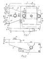
- a dressing unit 1, illustrated in Figures 1 to 4 has a base 2 on which a hydraulic rotator 3 is mounted. Extending axially from opposite sides of the hydraulic rotator 3 are two end portions 4 of an output shaft 5.
- a member 6 has the form, in plan view, of a U-shaped arm, as may be seen from Figure 1. Free limbs 7 of the U-shaped arm 6 are rotatably mounted upon the two end portions 4 of the output shaft 5, and are connected together by a cross-member 8 at an end region remote from the output shaft 5.
- the cross-member 8 has a flat face 9 on which a dressing assembly 10 is mounted.
- Dressing assembly 10 consists of a generally triangular toolpost 11 and a pair of dressing tools 12, disposed substantially centrally of the flat face 9.
- the toolpost 11 is located on the cross-member 8 by two dowels 13 and is secured to the cross-member 8 by a bolt 14. Alternatively, the tool post 11 may be simply bolted to the cross member 8.
- each prong 15 is provided with a respective inclined bore 16 in which a shank 17 of a respective one of the dressing tools 12 is received.
- each dressing tool 12 carries a diamond tip 18.
- the bores 16 are inclined at 90° to one another, such that the two diamond tips 18 are presented, perpendicular to one another. Whereas in the drawing the bores 16 are illustrated at 90° to each other, the invention is not restricted to this feature so that the diamond tips 18 may be inclined at any angle to perform the required dressing operation.
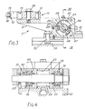
- the hydraulic rotator 3 is used to rotate the U-shaped arm 6 between a retracted or horizontal position, shown in Figures 1 to 5, and an operational or vertical position shown in Figure 6. It may be seen from Figures 3 and 4, that within the hydraulic rotator 3, the output shaft 5 is rotationally supported by two spaced apart bearings 19. Each bearing 19 is mounted in a bearing housing 20.
- a pair of seals 21 are also retained by the bearing housings 20 and are disposed along the output shaft 5.
- a lip-seal 22 is received on the output shaft 5 adjacent each bearing 19. The seals 21 and 22 serve to prevent the passage of fluid, hydraulic or otherwise, along the output shaft 5.
- An annular chamber 23, formed between the bearing housings 20 and the output shaft 5, has a pair of fixed radial vanes 24 axially disposed along a cylindrical wall 25 of the chamber 23 and effectively dividing the chamber into two arcuate chambers.
- the fixed radial vanes 24 each coact with one of two rotatable vanes 26, rigidly attached to the output shaft 5, to form two hydraulic operating chambers 27 between opposing faces 28, 29 of the respective vanes 24, 26.
- Rotation of the output shaft 5 is effected by the passage of hydraulic fluid, supplied to the dressing unit 1 by way of a pipe connect 30, to or from the operating chambers 27. It will be appreciated that only one arcuate chamber and rotatable vane may be used.
- the dressing unit 1 is shown attached to a table 33 of a CNC surface grinding machine 34 by two mounting bolts 35. Also mounted on the table 33 is a magnetic chuck 36 on which a workpiece 37 is retained.
- the U-shaped arm 6 When the U-shaped arm 6 is in the horizontal position, shown in Figure 5, it lies below the plane of an upper surface 38 of the magnetic chuck 36. Thus, the U-shaped arm 6 is retained away from a normal operating region of a grinding wheel 39 of the surface grinding machine 34.
- the dressing unit 1 controlled by a CNC system of the surface grinding machine 34, is raised to the vertical position shown in Figure 6. In this position the dressing tools 12 are disposed above the level of the workpiece 37 as viewed in Figure 6. Under operator control both sides and the periphery of the grinding wheel 39 are caused to approach and touch in turn each diamond tip 128 to determine a datum position of each tip 18. Once the two datum positions are defined an automated dressing operation can commence.
- the U-shaped arm 6 is returned to the horizontal position. Normal grinding of the workpiece 37 can subsequently proceed.
- a particular advantage of the invention is that profiling of the grinding wheel 39 can be controlled by the CNC system without complex setting up of dressing tools 12.
- a further advantage is that with the U-shaped arm 6 in the vertical position, the dressing tools 12 are within the normal operating region of the grinding wheel 39. Therefore, no time or machining capacity is wasted in relative movement of the grinding wheel 39 to an isolated region of the table 33, as required by the described prior art construction.
- the grinding wheel 39 is dressed at a location above that of the workpiece 37, the grinding "envelope" (that is the table area and grinding zone above it) is not reduced or otherwise impaired. Furthermore, when the toolpost 11 is retracted, when necessary, the full area of the table 33 can be ground without fouling the diamond dressing assembly 10.
Landscapes
- Engineering & Computer Science (AREA)
- Mechanical Engineering (AREA)
- Grinding-Machine Dressing And Accessory Apparatuses (AREA)
Applications Claiming Priority (2)
| Application Number | Priority Date | Filing Date | Title |
|---|---|---|---|
| GB8704436 | 1987-02-25 | ||
| GB878704436A GB8704436D0 (en) | 1987-02-25 | 1987-02-25 | Dressing unit |
Publications (1)
| Publication Number | Publication Date |
|---|---|
| EP0280483A1 true EP0280483A1 (fr) | 1988-08-31 |
Family
ID=10612930
Family Applications (1)
| Application Number | Title | Priority Date | Filing Date |
|---|---|---|---|
| EP88301460A Withdrawn EP0280483A1 (fr) | 1987-02-25 | 1988-02-22 | Dispositif de dressage |
Country Status (3)
| Country | Link |
|---|---|
| EP (1) | EP0280483A1 (fr) |
| JP (1) | JPS63306880A (fr) |
| GB (2) | GB8704436D0 (fr) |
Cited By (1)
| Publication number | Priority date | Publication date | Assignee | Title |
|---|---|---|---|---|
| NL1005935C2 (nl) * | 1997-04-29 | 1998-11-02 | Albert Geuzinge | Afritsen van slijpstenen. |
Citations (3)
| Publication number | Priority date | Publication date | Assignee | Title |
|---|---|---|---|---|
| FR853103A (fr) * | 1939-01-18 | 1940-03-11 | Dispositif pour rectifier les meules | |
| US4202317A (en) * | 1978-03-31 | 1980-05-13 | Anthony Kushigian | Grinding wheel dresser |
| US4480626A (en) * | 1982-10-22 | 1984-11-06 | Ibrahim Ibrahimpasic | Device for dressing grinding wheels |
Family Cites Families (4)
| Publication number | Priority date | Publication date | Assignee | Title |
|---|---|---|---|---|
| FR1682672A (fr) * | 1925-08-07 | |||
| GB340335A (en) * | 1929-10-02 | 1931-01-01 | Auto Machinery Company Ltd | Radial grinding machines |
| FR1593220A (fr) * | 1967-11-18 | 1970-07-03 | ||
| US3640030A (en) * | 1969-03-03 | 1972-02-08 | Gleason Works | Method for grinding toothed faced members |
-
1987
- 1987-02-25 GB GB878704436A patent/GB8704436D0/en active Pending
-
1988
- 1988-02-22 EP EP88301460A patent/EP0280483A1/fr not_active Withdrawn
- 1988-02-24 GB GB08804272A patent/GB2201618A/en active Pending
- 1988-02-25 JP JP4325888A patent/JPS63306880A/ja active Pending
Patent Citations (3)
| Publication number | Priority date | Publication date | Assignee | Title |
|---|---|---|---|---|
| FR853103A (fr) * | 1939-01-18 | 1940-03-11 | Dispositif pour rectifier les meules | |
| US4202317A (en) * | 1978-03-31 | 1980-05-13 | Anthony Kushigian | Grinding wheel dresser |
| US4480626A (en) * | 1982-10-22 | 1984-11-06 | Ibrahim Ibrahimpasic | Device for dressing grinding wheels |
Non-Patent Citations (1)
| Title |
|---|
| DE - B - K22440 Ib/49d (KLINGELNBERG) * |
Cited By (2)
| Publication number | Priority date | Publication date | Assignee | Title |
|---|---|---|---|---|
| NL1005935C2 (nl) * | 1997-04-29 | 1998-11-02 | Albert Geuzinge | Afritsen van slijpstenen. |
| EP0876875A1 (fr) * | 1997-04-29 | 1998-11-11 | Albert Geuzinge | Dressage de meules de rectification |
Also Published As
| Publication number | Publication date |
|---|---|
| GB2201618A (en) | 1988-09-07 |
| JPS63306880A (ja) | 1988-12-14 |
| GB8704436D0 (en) | 1987-04-01 |
| GB8804272D0 (en) | 1988-03-23 |
Similar Documents
| Publication | Publication Date | Title |
|---|---|---|
| US8500518B2 (en) | Method of grinding an indexable insert and grinding wheel for carrying out the grinding method | |
| CA2703090A1 (fr) | Porte-outil | |
| EP0341968A3 (fr) | Machine-outil à commande numérique | |
| JP4344690B2 (ja) | クランプ組立品 | |
| JPS61244455A (ja) | 研削盤 | |
| JPS5927284B2 (ja) | 鋳物バリ取り機 | |
| JP2003094262A (ja) | クランクシャフト加工ラインの加工方法 | |
| EP0169286A3 (fr) | Toupie | |
| JPS6232050B2 (fr) | ||
| EP0280483A1 (fr) | Dispositif de dressage | |
| US4376357A (en) | Machine tools | |
| US5137397A (en) | Cutting tool and method for using the same | |
| CN217095698U (zh) | 一种轧辊的端面多刀粗车装置 | |
| KR0177327B1 (ko) | 공작물의 슬롯 깊이조절용 가공공구 | |
| CA1247349A (fr) | Mecanisme d'indexage d'outils de coupe | |
| GB1575251A (en) | Machine tools | |
| Nakagawa et al. | Development of a new turning center for grinding ceramic materials | |
| JPH01103217A (ja) | 正面フライス | |
| US4467564A (en) | Arrangement of a measurement controlling device in circular grinding machines | |
| JPS61214903A (ja) | 旋盤 | |
| US4404772A (en) | Cylindrical grinding machine | |
| CN217070800U (zh) | 一种卧式双面镗铣加工系统 | |
| US3811234A (en) | Method of forming workpieces by abrading | |
| CN209831122U (zh) | 一种半自动铣刀研磨机 | |
| JPS6195862A (ja) | フライス工具の研削方法 |
Legal Events
| Date | Code | Title | Description |
|---|---|---|---|
| PUAI | Public reference made under article 153(3) epc to a published international application that has entered the european phase |
Free format text: ORIGINAL CODE: 0009012 |
|
| AK | Designated contracting states |
Kind code of ref document: A1 Designated state(s): AT BE CH DE ES FR GR IT LI LU NL SE |
|
| 17P | Request for examination filed |
Effective date: 19890223 |
|
| STAA | Information on the status of an ep patent application or granted ep patent |
Free format text: STATUS: THE APPLICATION HAS BEEN WITHDRAWN |
|
| 17Q | First examination report despatched |
Effective date: 19900622 |
|
| 18W | Application withdrawn |
Withdrawal date: 19900627 |