EP0280546B1 - Compas azimutal à main - Google Patents
Compas azimutal à main Download PDFInfo
- Publication number
- EP0280546B1 EP0280546B1 EP88301617A EP88301617A EP0280546B1 EP 0280546 B1 EP0280546 B1 EP 0280546B1 EP 88301617 A EP88301617 A EP 88301617A EP 88301617 A EP88301617 A EP 88301617A EP 0280546 B1 EP0280546 B1 EP 0280546B1
- Authority
- EP
- European Patent Office
- Prior art keywords
- compass
- sensor
- hand
- bearing
- longitudinal
- Prior art date
- Legal status (The legal status is an assumption and is not a legal conclusion. Google has not performed a legal analysis and makes no representation as to the accuracy of the status listed.)
- Expired
Links
- 210000003811 finger Anatomy 0.000 claims description 11
- 210000003813 thumb Anatomy 0.000 claims description 10
- 230000000007 visual effect Effects 0.000 claims description 8
- 230000007595 memory recall Effects 0.000 claims description 3
- 210000003414 extremity Anatomy 0.000 claims description 2
- 230000015654 memory Effects 0.000 description 6
- 238000003825 pressing Methods 0.000 description 5
- 230000001133 acceleration Effects 0.000 description 2
- 238000005286 illumination Methods 0.000 description 2
- 230000010355 oscillation Effects 0.000 description 2
- YZCKVEUIGOORGS-NJFSPNSNSA-N Tritium Chemical compound [3H] YZCKVEUIGOORGS-NJFSPNSNSA-N 0.000 description 1
- 230000002411 adverse Effects 0.000 description 1
- 239000002775 capsule Substances 0.000 description 1
- 238000010586 diagram Methods 0.000 description 1
- 239000007788 liquid Substances 0.000 description 1
- 238000005259 measurement Methods 0.000 description 1
- 229920002379 silicone rubber Polymers 0.000 description 1
- 239000004945 silicone rubber Substances 0.000 description 1
- 229910052722 tritium Inorganic materials 0.000 description 1
- 210000000707 wrist Anatomy 0.000 description 1
Images


Classifications
-
- G—PHYSICS
- G01—MEASURING; TESTING
- G01C—MEASURING DISTANCES, LEVELS OR BEARINGS; SURVEYING; NAVIGATION; GYROSCOPIC INSTRUMENTS; PHOTOGRAMMETRY OR VIDEOGRAMMETRY
- G01C17/00—Compasses; Devices for ascertaining true or magnetic north for navigation or surveying purposes
- G01C17/02—Magnetic compasses
- G01C17/28—Electromagnetic compasses
- G01C17/30—Earth-inductor compasses
Definitions
- This invention relates to hand bearing compasses.
- Hand bearing compasses are commonly used in navigation to take bearing of known marks in order to obtain a fix of position.
- the conventional hand bearing compass has a liquid damped compass card arrangement provided with a diametrical sight-line for alignment with the chosen distant mark.
- the body of the compass is usually adapted to be held in one hand, commonly having an elongate handle projecting axially downwardly beneath the card which makes the compass bulky in three dimensions and consequently inconvenient for storage and portability.
- To keep the card horizontal it is pendulously mounted on a central pivot, but this has the consequence that lateral acceleration caused by sea motion will cause rotary oscillation of the card. This make the instrument difficult to read at sea.
- Our European Patent 113 221 describes an electronic magnetic fluxgate that can be used as a direction finder. Such a sensor still needs to be held horizontally, because the earth's magnetic field has inclination and measurement of any component other than the horizontal will produce inconsistencies. If the sensor were provided with a gimbal system to keep it horizontal the gimbal would be disturbed by lateral accelerations caused by sea motion and errors would be introduced. Gimbal errors have therefore to be eliminated by fixing the magnetic fluxgate relative to the instrument body and finding some means of aligning the instrument body by hand in the horizontal plane.
- WO 85/05444 (Tschannen) describes a hand compass having a gimballed magnetometer-type sensor in a flat rectangular body with a single central sighting channel. A display on the body gives a continuous digital readout of the bearing along the sighting channel.
- the problem addressed herein is to provide a hand bearing compass which can to some extent meet the demands of alignment, compactness, easy portability and operability preferably either right- or left-handed while avoiding the rotary oscillation errors and inconsistencies associated with conventional hand bearing compasses.
- the invention provides a hand bearing compass comprising:
- the invention provides a hand bearing compass comprising:
- the flat body of the present compass makes it neat and compact, such that it may be e.g. stored in a pocket or hung round the neck without inconvenience, while by having the sights and actuators out of line in this manner but in a symmetrical arrangement, the compass may be used in either hand without the fingers obscuring the sighting line. Furthermore, horizontal alignment of the sensor may be achieved without the need for gimballed mounting of the sensor and concomitant errors.
- Each longitudinal sight or sights preferably comprises one or more projections, such as longitudinally spaced foresight and rear sight, or a single elongate longitudinal ridge, defining the viewing axis so that the user can line the sight up with the mark whose bearing is being measured.
- the pareferred direction-finding sensor is a two- axis magnetometer, and in particular an electronic magnetic fluxgate system such as described in our European Patent 113 221.
- Such a system and associated circuitry may be associated with the or each actuator of the compass so as to measure a bearing in accordance with the orientation of the compass's viewing axis at the time the actuator is pressed.
- the measured bearing value, as well as being displayed on a display of the compass may be storable in a memory for later recall.
- electronic circuitry associated with the sensor comprising means, such as a microprocessor, for storing in memory the values of bearings measured by a sequence of operations of the actuator.
- the values of the bearings may then be recalled, in their original sequence, to a read-out display of the compass upon successive operations of a memory recall actuator.
- This may provide a substantial advantage e.g. when obtaining a fix of position using multiple bearings, since the bearings can be measured in rapid succession without the need for memorising or writing which may be extremely inconvenient or difficult in adverse conditions.
- the or each actuator may be a push button in a flat upper face of the compass. It is preferred to provide a depression in the body directly opposite the button in the opposite face of the compass, so that it may be gripped naturally with a finger or thumb on the button and a thumb or finger engaging the depression, so as to avoid inadvertent tilting of the body when pressing the button.
- the compass body is preferably thin and flat, so as to be easily carried in a pocket.
- the longitudinal sight is directional, i.e. that it serves to distinguish the front of the compass from the back so as to avoid 180 ° errors in bearings.
- the front projections may differ from the rear ones.
- a sight may comprise fin-like lugs projecting from the flat surface and oriented lengthwise, the foresight being a single lug viewable end- on through the gap between a pair of similar lugs forming a rear sight. Both rear and foresights may be provided with illumination e.g., "beta lights", for use at night.
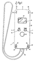
- the first embodiment is a compass having a flat rectangular body 1 of plastic, formed by rectangular top and bottom casing parts 2,3 joined edge to edge.
- the short front and rear edges 4,5 of the body are slightly curved, and their corners with the long straight side edges 6,7 rounded so that the compass may conveniently be carried in a pocket.
- the ends of a lanyard loop 10 are anchored and this may be used to hang the compass around the user's neck.
- the casing parts 2,3 define an internal cavity containing working parts of the compass. Principal among these is a direction finding sensor comprising a two-coil magnetic fluxgate 8 for measuring the orientation in the plane of the compass body 1 of magnetic fields.
- the plane of the sensor 8 parallel with the general compass body plane is a direction-finding plane in which it is adapted to measure bearings. In view of the inclination of the earth's magnetic field it is necessary for the plane to be consistently horizontally aligned in use if consistent readings are to be obtained, and the manner in which this is done is described further below.
- the compass casing also contains microprocessor circuitry 9 necessary for the working of the fluxgate 8, such that by pressing an actuating button 15 the orientation reading of the fluxgate may be both stored in a memory and visibly indicated on an LCD display 16.
- the microprocessor has nine memories 60 in which values of up to nine bearings measured on pressing of the button 15 can be stored in sequence. It also provides means for recalling these values in their measured sequence to the display 16 upon successive pressings of the memory recall button 13 (MEM).
- the circuitry further comprises a timing circuit 62 that can be actuated by the second auxiliary button 14 (TIMER). Power for the fluxgate circuitry is derived from batteries (not shown) in a battery chamber 18 accessible by way of a removable circular lid 19 underneath the front end of the body 1.
- the body 1 has a flat upper surface 20, and the layout of features on this is symmetrical about the median section plane of Figure 2.
- Right-hand and left-hand longitudinal sights 22,23 are provided towards those respective sides of the surface 20, equally spaced from the median plane.
- Each sight comprises a foresight 28,29 close to the respective front corner of the surface 20, and a corresponding rear sight 30,31 close to the respective rear corner.
- the foresights 28,29 are single fin-shaped lugs projecting from the surface 20, with flat sides 33, steeply sloping rear faces 34 and more gently sloping front faces 35, and the lengthwise direction of each lug is parallel with that of the compass as a whole.
- the rear sights comprise pairs of lugs similar to those of the foresights, the lugs 40,41 of each pair being spaced by a channel 42,43 such that parallel viewing axes or lines of sight are defined along the body 1 from the channels 42,43 to their respective foresights 28.29.
- the fluxgate system is set so as to measure the magnetic bearing parallel to these sight lines when aligned horizontally.
- a "beta" light i.e. a fluorescent tritium-filled capsule, is provided in each of the rear sight channels 42,43 and on the rear face 34 of each foresight so that the sights can be used in the dark; other forms of illumination could be used.
- the actuator - a flexible circular silicone rubber button 15 - for the fluxgate device is mounted in the upper face 20 on the longitudinal centre line of the compass (and therefore equidistant from the two sight lines) slightly towards the rear of the body 1. Also centrally positioned but forward of the button 15, is a window 45 behind which the LCD display 16 of the fluxgate device is mounted.
- the lower surface 21 of the compass body 1 is largely flat except for a circular depression 46 exactly opposing the position of the actuator button 15 on the upper face.
- the compass To use the compass in e.g. the right hand it is gripped in that hand with the thumb engaging the depression 46 and a finger on the button 15. Because the sight 23 on the left side is spaced laterally from the centre line, the viewing axis that it defines is not interrupted by the fingers gripping the body. The compass is then held up in front of the user's face and the left foresight 29, the channel 43 of the left rear sight and the mark whose bearing is being taken brought into line, viewing along the direction of arrow B ( Figure 1). Since foresight and rear sight are on the same level of the body and the mark chosen is typically distant, this naturally brings the longitudinal axis of the compass horizontal.
- the flat upper surface 20 of the compass seen from its rear edge as a straight index, is then aligned with e.g. the horizon so that lateral horizontality is also achieved, about the viewing axis, and the fluxgate device measures an accurate bearing of the viewing axis.
- This bearing is then taken by pressing the button 15, and because the right-hand thumb naturally engages the depression 46 directly under the button there is no tendency for the compass to twist out of alignment as this is done.
- the measured bearing is stored in the first memory of the microprocessor 9 and at the same time displayed on the LCD display 16. If a number of bearings are to be taken this can be done as above, and each is immediately stored in one of the nine memories.
- the bearing values are then brought back to the display 16 in the order in which they were taken, using the recall button 13.
- loop lanyard 10 attached to the extremity of the compass body 1. Normally this is worn around the neck or wrist or attached to clothing; when in use it can be put under slight tension to steady the compass as it is held centrally between thumb and finger of one hand
- Figures 4 and 5 show a second embodiment with a body 1 corresponding generally in shape with that of the first embodiment, and provided with a similar fluxgate direction sensor, microprocessor 9 and display 16.
- a body 1 corresponding generally in shape with that of the first embodiment, and provided with a similar fluxgate direction sensor, microprocessor 9 and display 16.
- buttons 54,55 for the sensor disposed symmetrically either side of the sight line, and each has its corresponding depression 56,57 on the undersurface of the body.
- sighting is always performed along the same line C ( Figure 4), while the right-hand use the right-hand button 55 is used, for left-hand use the left-hand button 54.
Landscapes
- Physics & Mathematics (AREA)
- Engineering & Computer Science (AREA)
- Radar, Positioning & Navigation (AREA)
- Remote Sensing (AREA)
- Life Sciences & Earth Sciences (AREA)
- Environmental & Geological Engineering (AREA)
- General Life Sciences & Earth Sciences (AREA)
- Geology (AREA)
- Electromagnetism (AREA)
- General Physics & Mathematics (AREA)
- Measuring Magnetic Variables (AREA)
Claims (8)
Applications Claiming Priority (2)
| Application Number | Priority Date | Filing Date | Title |
|---|---|---|---|
| GB878704560A GB8704560D0 (en) | 1987-02-26 | 1987-02-26 | Hand bearing compass |
| GB8704560 | 1987-02-26 |
Publications (3)
| Publication Number | Publication Date |
|---|---|
| EP0280546A2 EP0280546A2 (fr) | 1988-08-31 |
| EP0280546A3 EP0280546A3 (en) | 1989-04-12 |
| EP0280546B1 true EP0280546B1 (fr) | 1990-11-14 |
Family
ID=10612999
Family Applications (1)
| Application Number | Title | Priority Date | Filing Date |
|---|---|---|---|
| EP88301617A Expired EP0280546B1 (fr) | 1987-02-26 | 1988-02-25 | Compas azimutal à main |
Country Status (4)
| Country | Link |
|---|---|
| US (1) | US4894922A (fr) |
| EP (1) | EP0280546B1 (fr) |
| DE (1) | DE3861029D1 (fr) |
| GB (1) | GB8704560D0 (fr) |
Families Citing this family (22)
| Publication number | Priority date | Publication date | Assignee | Title |
|---|---|---|---|---|
| US5216308A (en) * | 1989-05-25 | 1993-06-01 | Avcon-Advanced Controls Technology, Inc. | Magnetic bearing structure providing radial, axial and moment load bearing support for a rotatable shaft |
| DE4001657A1 (de) * | 1990-01-18 | 1991-07-25 | Carl Steiner | Vorrichtung zur positionsmessung |
| JP2935047B2 (ja) * | 1990-03-13 | 1999-08-16 | カシオ計算機株式会社 | 電子コンパス |
| US5269065A (en) * | 1990-03-20 | 1993-12-14 | Casio Computer Co., Ltd. | Compass including means for displaying constellation data |
| US5216816A (en) * | 1990-03-20 | 1993-06-08 | Casio Computer Co., Ltd. | Compass |
| US5199178A (en) * | 1991-10-23 | 1993-04-06 | Apac, Inc. | Thin film compass and method for manufacturing the same |
| DE69218233T2 (de) * | 1991-11-08 | 1997-09-25 | Precision Navigation Inc | Referenzzeiger für eine kompassanzeigeeinrichtung |
| CH683128A5 (de) * | 1992-03-26 | 1994-01-14 | Recta Sa | Tragbarer elektronischer Fahrzeugkompass. |
| US5315197A (en) * | 1992-04-30 | 1994-05-24 | Avcon - Advance Controls Technology, Inc. | Electromagnetic thrust bearing using passive and active magnets, for coupling a rotatable member to a stationary member |
| GB9307967D0 (en) * | 1993-04-17 | 1993-06-02 | Manley Joseph C | Intelligent electronic map reading compass |
| US6535210B1 (en) | 1995-06-07 | 2003-03-18 | Geovector Corp. | Vision system computer modeling apparatus including interaction with real scenes with respect to perspective and spatial relationship as measured in real-time |
| US5600611A (en) * | 1995-10-04 | 1997-02-04 | Timex Corporation | Wrist mountable compass |
| US6169922B1 (en) | 1998-11-18 | 2001-01-02 | Acorn Cardiovascular, Inc. | Defibrillating cardiac jacket with interwoven electrode grids |
| USD440397S1 (en) | 1999-02-17 | 2001-04-17 | Manufacture d'Articles de Precision et de Dessin—M.A.P.E.D. | Case for a compass |
| US6522292B1 (en) | 2000-02-23 | 2003-02-18 | Geovector Corp. | Information systems having position measuring capacity |
| US7031875B2 (en) | 2001-01-24 | 2006-04-18 | Geo Vector Corporation | Pointing systems for addressing objects |
| USD466823S1 (en) | 2001-05-16 | 2002-12-10 | Sunrich Manufactory Limited | Compass and lighted magnifier |
| US20040219961A1 (en) * | 2003-04-08 | 2004-11-04 | Ellenby Thomas William | Computer games having variable execution dependence with respect to spatial properties of a mobile unit. |
| FI117948B (fi) | 2004-06-16 | 2007-04-30 | Suunto Oy | Rannetietokone ja menetelmä sen yhteydessä |
| US20060190812A1 (en) * | 2005-02-22 | 2006-08-24 | Geovector Corporation | Imaging systems including hyperlink associations |
| US10012731B2 (en) | 2014-04-03 | 2018-07-03 | Johnson Outdoors Inc. | Sonar mapping system |
| US10545235B2 (en) | 2016-11-01 | 2020-01-28 | Johnson Outdoors Inc. | Sonar mapping system |
Family Cites Families (10)
| Publication number | Priority date | Publication date | Assignee | Title |
|---|---|---|---|---|
| DE659518C (de) * | 1936-12-15 | 1938-05-05 | Stockert & Sohn C | Marschkompass mit Visiereinrichtung |
| GB561336A (en) * | 1941-07-24 | 1944-05-16 | Recta Sa | Improvements in and relating to pocket compasses |
| US2955357A (en) * | 1957-03-11 | 1960-10-11 | Uebelhardt Roger | Wrist watch |
| US3248793A (en) * | 1962-11-07 | 1966-05-03 | Warren D Anderson | Navigational instrument |
| DE3370861D1 (en) * | 1982-12-30 | 1987-05-14 | Nautech Ltd | Compass systems |
| JPS61502211A (ja) * | 1984-05-22 | 1986-10-02 | カ− チヤネン− エレクトロ−ニク アクチエン ゲゼルシヤフト | 電子コンパス |
| GB2159278B (en) * | 1984-05-23 | 1988-04-13 | Stc Plc | Heading sensor |
| JPH0772689B2 (ja) * | 1984-09-04 | 1995-08-02 | 東北金属工業株式会社 | 方位標定装置 |
| FR2582389B1 (fr) * | 1985-05-21 | 1987-06-26 | Lanchier Jean Marc | Procede et dispositif pour porter sur une carte la position d'un observateur |
| US4668100A (en) * | 1985-09-03 | 1987-05-26 | Citizen Watch Co., Ltd. | Electronic equipment with geomagnetic direction sensor |
-
1987
- 1987-02-26 GB GB878704560A patent/GB8704560D0/en active Pending
-
1988
- 1988-02-25 EP EP88301617A patent/EP0280546B1/fr not_active Expired
- 1988-02-25 DE DE8888301617T patent/DE3861029D1/de not_active Expired - Lifetime
- 1988-02-26 US US07/160,843 patent/US4894922A/en not_active Expired - Fee Related
Also Published As
| Publication number | Publication date |
|---|---|
| DE3861029D1 (de) | 1990-12-20 |
| EP0280546A3 (en) | 1989-04-12 |
| GB8704560D0 (en) | 1987-04-01 |
| US4894922A (en) | 1990-01-23 |
| EP0280546A2 (fr) | 1988-08-31 |
Similar Documents
| Publication | Publication Date | Title |
|---|---|---|
| US4894922A (en) | Hand bearing compass | |
| EP1242784B1 (fr) | Compas numerique dote d'une capacite de detection multiple et de signalisation | |
| US5983514A (en) | Tape measure with manual entry electronic measurement recording feature | |
| US4977509A (en) | Personal multi-purpose navigational apparatus and method for operation thereof | |
| US5539706A (en) | Pulsimeter provided with or without a pedometer | |
| KR100554535B1 (ko) | 타깃위치의방향을나타내도록배열된,gps리시버를포함한시계 | |
| JP2012500395A (ja) | 方角を指し示すカード | |
| KR910017194A (ko) | 방위계 | |
| HK84696A (en) | Electronic compass | |
| US5572371A (en) | Viewer assemblies and viewable material adapted thereto | |
| US4462164A (en) | Orienteering compass | |
| US3609545A (en) | Handheld measuring instrument with multiple controls operable by the holding hand | |
| JPS6036901A (ja) | ペンシル型距離測定機 | |
| CN217818731U (zh) | 用于无人机航拍的野外控点装置 | |
| US5060390A (en) | Navigation aid | |
| US4081912A (en) | Magnetic bearing plotting and sighting device | |
| US4245393A (en) | Instant position finder and course plotter | |
| CN218381027U (zh) | 一种地质罗盘 | |
| US3919782A (en) | Magnetic compass assembly | |
| SU1822493A3 (en) | Compass for sport orientation | |
| JPH0468572B2 (fr) | ||
| EP0621459A1 (fr) | Compas électronique pour la lecture d'une carte | |
| JPS58219407A (ja) | 歩行距離計 | |
| US2472420A (en) | Touch signal level | |
| JPH049536Y2 (fr) |
Legal Events
| Date | Code | Title | Description |
|---|---|---|---|
| PUAI | Public reference made under article 153(3) epc to a published international application that has entered the european phase |
Free format text: ORIGINAL CODE: 0009012 |
|
| AK | Designated contracting states |
Kind code of ref document: A2 Designated state(s): DE FR GB SE |
|
| PUAL | Search report despatched |
Free format text: ORIGINAL CODE: 0009013 |
|
| AK | Designated contracting states |
Kind code of ref document: A3 Designated state(s): DE FR GB SE |
|
| 17P | Request for examination filed |
Effective date: 19890724 |
|
| 17Q | First examination report despatched |
Effective date: 19890908 |
|
| RBV | Designated contracting states (corrected) |
Designated state(s): DE FR GB |
|
| GRAA | (expected) grant |
Free format text: ORIGINAL CODE: 0009210 |
|
| AK | Designated contracting states |
Kind code of ref document: B1 Designated state(s): DE FR GB |
|
| REF | Corresponds to: |
Ref document number: 3861029 Country of ref document: DE Date of ref document: 19901220 |
|
| ET | Fr: translation filed | ||
| PLBE | No opposition filed within time limit |
Free format text: ORIGINAL CODE: 0009261 |
|
| STAA | Information on the status of an ep patent application or granted ep patent |
Free format text: STATUS: NO OPPOSITION FILED WITHIN TIME LIMIT |
|
| 26N | No opposition filed | ||
| REG | Reference to a national code |
Ref country code: FR Ref legal event code: CD |
|
| PGFP | Annual fee paid to national office [announced via postgrant information from national office to epo] |
Ref country code: GB Payment date: 20000215 Year of fee payment: 13 |
|
| PGFP | Annual fee paid to national office [announced via postgrant information from national office to epo] |
Ref country code: FR Payment date: 20000219 Year of fee payment: 13 Ref country code: DE Payment date: 20000219 Year of fee payment: 13 |
|
| PG25 | Lapsed in a contracting state [announced via postgrant information from national office to epo] |
Ref country code: GB Free format text: LAPSE BECAUSE OF NON-PAYMENT OF DUE FEES Effective date: 20010225 |
|
| GBPC | Gb: european patent ceased through non-payment of renewal fee |
Effective date: 20010225 |
|
| PG25 | Lapsed in a contracting state [announced via postgrant information from national office to epo] |
Ref country code: FR Free format text: LAPSE BECAUSE OF NON-PAYMENT OF DUE FEES Effective date: 20011031 |
|
| REG | Reference to a national code |
Ref country code: FR Ref legal event code: ST |
|
| PG25 | Lapsed in a contracting state [announced via postgrant information from national office to epo] |
Ref country code: DE Free format text: LAPSE BECAUSE OF NON-PAYMENT OF DUE FEES Effective date: 20011201 |