EP0280553A2 - Rechnerunterstützte Kontrolle von Prozessabläufen - Google Patents
Rechnerunterstützte Kontrolle von Prozessabläufen Download PDFInfo
- Publication number
- EP0280553A2 EP0280553A2 EP88301635A EP88301635A EP0280553A2 EP 0280553 A2 EP0280553 A2 EP 0280553A2 EP 88301635 A EP88301635 A EP 88301635A EP 88301635 A EP88301635 A EP 88301635A EP 0280553 A2 EP0280553 A2 EP 0280553A2
- Authority
- EP
- European Patent Office
- Prior art keywords
- operator
- response
- electrically
- signal
- action
- Prior art date
- Legal status (The legal status is an assumption and is not a legal conclusion. Google has not performed a legal analysis and makes no representation as to the accuracy of the status listed.)
- Granted
Links
Images





Classifications
-
- G—PHYSICS
- G21—NUCLEAR PHYSICS; NUCLEAR ENGINEERING
- G21D—NUCLEAR POWER PLANT
- G21D3/00—Control of nuclear power plant
-
- G—PHYSICS
- G21—NUCLEAR PHYSICS; NUCLEAR ENGINEERING
- G21D—NUCLEAR POWER PLANT
- G21D3/00—Control of nuclear power plant
- G21D3/001—Computer implemented control
-
- G—PHYSICS
- G06—COMPUTING OR CALCULATING; COUNTING
- G06F—ELECTRIC DIGITAL DATA PROCESSING
- G06F3/00—Input arrangements for transferring data to be processed into a form capable of being handled by the computer; Output arrangements for transferring data from processing unit to output unit, e.g. interface arrangements
- G06F3/01—Input arrangements or combined input and output arrangements for interaction between user and computer
- G06F3/03—Arrangements for converting the position or the displacement of a member into a coded form
- G06F3/033—Pointing devices displaced or positioned by the user, e.g. mice, trackballs, pens or joysticks; Accessories therefor
-
- G—PHYSICS
- G21—NUCLEAR PHYSICS; NUCLEAR ENGINEERING
- G21C—NUCLEAR REACTORS
- G21C17/00—Monitoring; Testing ; Maintaining
-
- G—PHYSICS
- G21—NUCLEAR PHYSICS; NUCLEAR ENGINEERING
- G21D—NUCLEAR POWER PLANT
- G21D3/00—Control of nuclear power plant
- G21D3/04—Safety arrangements
-
- Y—GENERAL TAGGING OF NEW TECHNOLOGICAL DEVELOPMENTS; GENERAL TAGGING OF CROSS-SECTIONAL TECHNOLOGIES SPANNING OVER SEVERAL SECTIONS OF THE IPC; TECHNICAL SUBJECTS COVERED BY FORMER USPC CROSS-REFERENCE ART COLLECTIONS [XRACs] AND DIGESTS
- Y02—TECHNOLOGIES OR APPLICATIONS FOR MITIGATION OR ADAPTATION AGAINST CLIMATE CHANGE
- Y02E—REDUCTION OF GREENHOUSE GAS [GHG] EMISSIONS, RELATED TO ENERGY GENERATION, TRANSMISSION OR DISTRIBUTION
- Y02E30/00—Energy generation of nuclear origin
-
- Y—GENERAL TAGGING OF NEW TECHNOLOGICAL DEVELOPMENTS; GENERAL TAGGING OF CROSS-SECTIONAL TECHNOLOGIES SPANNING OVER SEVERAL SECTIONS OF THE IPC; TECHNICAL SUBJECTS COVERED BY FORMER USPC CROSS-REFERENCE ART COLLECTIONS [XRACs] AND DIGESTS
- Y02—TECHNOLOGIES OR APPLICATIONS FOR MITIGATION OR ADAPTATION AGAINST CLIMATE CHANGE
- Y02E—REDUCTION OF GREENHOUSE GAS [GHG] EMISSIONS, RELATED TO ENERGY GENERATION, TRANSMISSION OR DISTRIBUTION
- Y02E30/00—Energy generation of nuclear origin
- Y02E30/30—Nuclear fission reactors
Definitions
- This invention is directed to a method and apparatus for aiding an operator in executing step-by-step procedures during the operation of a complex process facility such as a nuclear power plant. More particularly, it involves a computer-based system which incorporates monitored plant data and interactive plant operator responses to recommend actions for step-by-step progression through a selected procedure and includes verification of operator responses, on-line review of completed steps, and logging of all data pertinent to procedure execution.
- the status tree system advises the operator of any threats to the critical safety functions, and suggests a procedure to be followed, the operator must still locate the recommended procedure in the paper procedures and then follow it manually step-by-step.
- the status tree system also does not keep the operator apprised of other plant conditions which the paper procedures require be monitored, but which do not directly affect the critical safety functions.
- Published EPC Application 0235958 is directed to a computer-based system which both assesses the plant data and provides guidance based on predetermined procedures.
- current plant data are used by the computer to trace a path through the logic of appropriate procedure steps in order to identify a recommended course of action.
- the course of action along with related data is displayed for the operator on one or more electronic display devices.
- the computer uses the plant data and the operator's interactive response to proceed to the next appropriate procedure step.
- the computer simultaneously monitors certain functions which must normally be continuously monitored by the operator. If a problem becomes apparent in any of these functions, the operator is alerted and appropriate actions are displayed.
- the invention in its broad form resides in method and apparatus as follows: In a complex process facility such as a nuclear power station having known logic step-by-step procedures, an apparatus for assisting an operator in the execution of said procedure steps, said apparatus comprising a plurality of sensors for generating sensor signals representative of the real-time value of plurality of process-parameters; storage means for storing electrical signals representative of the logic for the procedure steps of a plurality of step-by-step procedures, characterized by a digital computer programmed to sequentially select stored signals representative of the logic of a selected one of said procedure steps of one of said plurality of step-by-step procedures as a current sep, to repetitively process selected sensor signals to determine the status of a process condition selected by the current step, and to provide recommended action when the process condition is not verified by the sensor signals; a display device controlled by the digital computer for generating a visual display indicating the current step, the real-time status of the selected process condition, any recommended action, and instructions for an operator to generate an action
- a preferred embodiment described herein teaches a method and apparatus for on-line, machine-assisted execution by a human operator of procedures for a complex process facility in which the steps of a selected procedure stored in computer memory are sequentially presented to the operator on a display device.
- Process parameter signals are repetitively processed to automatically determine the status of a process condition addressed by the current step. Where the process condition is not verified by the parameter values, a visible textual statement of recommended operator action is presented on a display device together with instructions for the operator to generate an "ACTION COMPLETED" or "OVERRIDE" response. If the operator performs the recommended action, the repetitive processing of the parameter signals will detect a change in the associated parameter value and update the process condition.
- the next step in the procedure is selected as the current step. If the process condition is not verified when the operator enters an "ACTION COMPLETED” response, the next step will not be selected, and the step logic is repeated until an acceptable response is registered.
- the system requires verification by parameter sensors that the recommended action has been effective.
- the operator may enter an "OVERRIDE” response, and thus advance to the next step, but he is aware then that the recommended action is not verified by the sensors. This feature allows the system to advance to the next step when a component which should have been operated by the recommended action does not respond. It can also help the operator identify a faulty sensor when he knows from other indications that the action taken has been successful. By requiring the operator to enter the override response, the erroneous sensor reading is brought to his attention.
- a recommended action may require a prolonged period of time for completion.
- an "ACTION INITIATED” prompt is generated for such a step.
- the full display at the time of completion is stored as a permanent record for later review. This is especially useful in the case of an event where it is desired later to review the actions taken by the operator.
- the visual representations are also stored for on-line review of the previously executed steps without interruption of the current step. This is especially useful during a shift change to apprise the incoming crew of the course of events which have led to the current condition of the facility while the prior crew continues to execute the steps of the active procedure.
- Another aspect of the invention permits the operator to scan forward or backward in the active procedure, and to execute or re-execute prior steps if desired. This enables the operator to view the active procedure as a whole and provides improved flexibility.
- the invention is directed to improvements in the method and apparatus for monitoring the execution of process operating procedures disclosed in EPC patent application published under No. 0235958 and entitled "On-line Interactive Monitoring of the Execution of Process Operating Procedures".
- PWR pressurized water reactor
- the invention will be described as applied to a pressurized water reactor (PWR) nuclear power plant, but it should be realized that it has application to a variety of complex process facilities such as, for example, chemical plants, refineries and the like.
- PWR pressurized water reactor
- it is adaptable to various facilities where a human operator is required to follow preconceived, although not necessarily rigid, step-by-step procedures, and is most useful in those facilities in which the sequence of steps depends at least in part upon current conditions in the complex process facility.
- Figure 1 illustrates a PWR power plant adapted for implementing the above application of the invention.
- the plant 1 is instrumented with numerous sensors 3 which monitor various plant parameters such as temperatures, pressures, flows, radiation levels, tank levels, equipment status and the like.
- the signals, S, generated by the sensors are initially processed by instrumentation 5 which provides conventional signal processing such as surge protection, buffering, isolation, filtering, span control, conversion to engineering units, et cetera.
- Instrumentation 5 also generates logical signals representative of plant conditions of interest by comparing certain of the initially processed signals with set point values.
- the processed sensor signals and logical signals generated by the instrumentation 5 are supplied over the line 7 to the control board displays in the plant control room for visual presentation to the user 11, namely, the control room personnel.
- the control board displays 9 which are conventional, utilize the processed sensor signals to generate visual representations of the measured values of the associated parameters and the logical signals and to produce visual indications of the status of the plant conditions of interest.
- the operator uses this information in analyzing the state of the plant and its various subsystems and in making decisions such as, if, when, and what adjustments should be made to the plant controls 13. In making these decisions, the operator presently has access to paper procedures 15 which provide step-by-step guidance through a logical sequence of analysis and action.
- the initially processed sensor signals and the logical signals generated by the instrumentation 5 are also fed over a line 17 to plant computer 19 which performs surveillance and logging functions.
- This computer 19 also calculates certain parameters such as for instance the departure from nucleate boiling ratio (DNBR) and degrees of core exit coolant subcooling from the measured parameters. Some of these calculated parameters are transmitted to the control board displays 9 over lead 21 for presentation to the operator.
- DNBR departure from nucleate boiling ratio
- the present invention provides improvements to the system described in EPC patent application published under Serial No. 0235958, which in turn replaces the paper procedures 15 in providing guidance for the operator 11 in monitoring plant performance and manipulating the plant controls 13. It is an on-line tracking system which allows the operating staff to access and follow procedures in an easy, reliable and logical manner.
- the system performs its functions through the execution of several concurrent but independent tasks including a read task, a main task, a parallel process task, and a display task.
- the read task gathers the plant parameter information and processes it for use by the main task.
- the main task controls the flow of the procedures and of the individual steps of the current procedure, and performs the logging functions.
- the parallel process task tracks system or safety conditions that may affect plant operations.
- the display task generates the visual displays for interfacing with the operator.
- the system includes a digital computer 23 which receives sensor and logical signals from the instrumentation 5 and calculated parameter values from the plant computer 19.
- the computer 23 may consist of a single main frame unit with an operating system which supports real-time multi-task operations, or several microprocessors linked by a data highway, with each microprocessor handling a single task.
- the software may be resident in the plant computer 19 when that unit has a dual processing capability and the capacity to perform the routines required.
- the computer 23 interfaces to a display generator 25 (such as a Raster Tehcnology Model 1/80 unit) to provide the color graphics output of the procedures program on a visual display device such as a high-resolution color monitor 27.
- the user, or operator, 11 observes the visual display generated on the color monitor 27 and provides input to the system througha touch screen device 29 on the monitor, or an equivalent device such as a keyboard.
- Fig. 1 The architecture of the software for the system is illustrated within the broken line of Fig. 1 representing the computer 23.
- a library 31 of subroutines or overlays Central to the software package is a library 31 of subroutines or overlays, each of which embodies the logic and, as required, recommended action steps, for one procedure.
- This library of step-by-step procedures is stored in computer memory or in a high capacity, on-line device such as a computer disc.
- Operation of the system is initiated by a trigger 33 in response either to a user input from the touch screen 29, or to an indication of a particular set of plant conditions, such as a reactor trip, received from the control board displays 9 or the plant data processor 41.
- the trigger 33 activates a procedure selector 35 containing the necessary logic to select the appropriate procedure from the library 31 and to establish that procedure as the active procedure.
- a step selector 37 sequentially selects the steps of the active procedure one at a time for a current step processor 39.
- Inputs to the current step processor 39 are obtained from two sources.
- a plant data processor 41 collects plant data, including calculated parameters from the instrumentation 5 and plant computer 19, and transforms numerical (and analog) information into logical form for use in the procedure logic. For instance, a temperature signal is transformed into a logical signal which indicates whether the current value of the temperature is above or below a given set point value.
- the human user provides input to the current step processor through the touch screen or equivalent device 29 and a response processor 43. User inputs usually take the form of interactive responses to specific prompts generated by the current step processor 39.
- the current step proces simplysor 39 repetitively performs the step logic.
- the current step processor 39 repetitively checks the response processor 43 for an operator response to the instructions generated by the current step processor, as indicated by the dash-dot line in Fig. 1.
- the response processor communicates with the procedure selector 35 and step selector 37 to implement selection of a next step and, if necessary, a new procedure, dependent upon the user's response.
- a parallel condition processor 45 operates independently of the current step processor 39 to provide parallel, concurrent monitoring of overall plant and individual system conditions in areas not directly considered by the procedure in effect. If the parallel condition processor detects an unexpected conditon, such as might arise as a result of operations or casualties unrelated to the currently active procedure, a priority evaluator 47 applies to preset logic to determine whether the unexpected condition is sufficiently severe to recommend to the user, suspension of the current procedure in the current step processor 39 and initiation of a different course of action involving another procedure, to treat those conditions.
- text embedded in the logic of the current step processor 39 or the parallel condition processor 45 is passed to the display generator 25.
- the display generator accepts the specified lines of text and constructs a display image on the color monitor 27 as will be seen in more detail below.
- This display provides the user with information regarding plant and system status as seen both by the active procedure and by the parallel condition processor 45, with recommended action as required, and with appropriate instruction for the operator to generate user responses.
- the user observes the textual images produced by the display generator 25 on the color monitor 27 and communicates his desired responses by the way of the touch screen or equivalent 29, which transmits them to the response processor 43.
- the user's response is stored in a buffer 30, which may be incorporated in the touch screen device 29 as shown, so that the current step processor 39 can continue to repetitively execute the step logic without waiting for the user's response.
- User responses to action recommended by the current step processor typically resulting in indexing the step selector 37 to a next step in the active procedure.
- Responses to action recommended by the parallel condition processor 45 can result in a return to the current step, or a signal to the procedure selector 35 to transfer to another procedure.
- the last piece of software in the software package is a condition logger 53 which accepts current step information and parallel condition information from the current step processor 39 and parallel condition processor 45, respectively, in addition to operator responses received from the response processor 43, and generates a complete record of the displays presented to the operator, and the operator's responses.
- a permanent chronological record of the displays and responses is obtained by coupling a permanent copy device, such as a printer 55, or a magnetic tape recorder or the like, to the logger 53.
- An additional monitor 51 provides an on-line review capability which allows the operator to scan the recorder listing while simultaneously executing procedure steps.
- the additional monitor 51 is provided with a touch screen 52 or other device by which a user can initiate and control the on-line review.
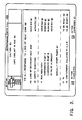
- Figure 2 illustrates the format of a typical display generated by the display generator 25 for presentation on the color monitor 27.
- the current clock time is displayed in the upper left-hand corner at 59.
- Information generated by the parallel condition processor is displayed in a box 61 just below the time.
- the system allows the user to understand overall system or safty status by displaying a summary of those items which are considered crucial in a window 63 at the left end of the box 61. This enables the users to judge at any time whether these items are satisfied or not.
- status tree information can be displayed in this block when pertinent to the current plant condition.
- the details of a suitable display are discussed in the related application. It is sufficient to say that each of the six safety functions in the exemplary display are represented by a horizontal bar graph. The greater the width of the particular bar graph, the more serious the situation.
- the system also allows the user to understand the status of the other conditions which require monitoring during the procedure execution.
- Notes and Cautions appear throughout a set of procedures. These relate to additional items which the user must remember to monitor, such as tank levels and component states.
- the system alleviates this burden on the operator's memory by automatically keeping track of these items. If a Note or Caution requires attention, the system informs the user of this fact along with a statement of action necessary, if any, to solve the problem, in the center window 65 of the box 61.
- a flashing indication appears in a special alert indicator window 67.
- Information related to the procedure being executed is presented in the large block 69 in the center of the display.
- the title of the active procedure is displayed at the top of the block at 71.
- Information related to the current step being executed is displayed between the dashed lines 73.
- a high-level statement of the step is presented first as at 75.
- the function of the procedure step 11 is to verify the reactor coolant system feed path. In this case, the condition is not verified, hence the high level statement reads "RCS FEED PATH - NOT VERIFIED".
- the system also informs the user of the status of the parameters or components which led to the high-level statement immediately below that statement at 77.
- these components are charging/safety injection pumps A and B, both of which are not running.
- the operator would have to check the status of these pumps on the control board displays personally in order to then come to the conclusion that the pumps were not running. Alignment of the safety injection valves is also required to establish the RCS feed path, but in the example, valve alignment is verified.
- the system also informs the user of the actions, if any, which are recommended in response to the current procedure step, through a verbal statement 79 below the component status.
- the recommended action is "MANUALLY START PUMPS".
- the system also displays at 81 above the current step, the high-level results statement of a preselected number, in the preferred embodiment two, of the previously executed steps of a current procedure.
- the high-level textual statement of the preselected number again preferably two, of the next steps in the procedure are displayed immediately below the current step at 83.
- User touch screen prompts or instructions for generating a response are presented at the bottom of the display below the block 69.
- Each step presents the operator with the choice of either accepting the status information and recommended action, if any, or in rejecting it.
- the operator accepts the recommendation by performing the action and then pressing the touch screen button 85 labeled "ACTION COMPLETED”. If the operator chooses to reject the recommendation, the touch screen button 87 labeled "ACTION OVERRIDDEN" is touched.
- the displays make extensive use of color coding to enhance the operator interface. Different colors are used to distinguish between parameter or component states, required actions, and high-level statements of procedure steps. Since the figures are monochromatic as presented, the various portions of the display are succeeded by one of the following symbols, which do not appear on the display, but are used here to indicate the following color designations: (b) blue (g) green (w) white (y) yellow
- the prompts are presented in the same color as the recommended action so that the operator knows whether he is responding to a current step or a continuously monitored condition. Thus, in the example, the prompts are yellow, indicating that they are to be used for indicating responses to the recommended action in the current step which is also in yellow.
- Action required in connection with a continuously monitored condition would be displayed in blue as would be the prompts so that the operator knows what function the response is associated with.
- reverse video is used. This is represented in Fig. 2 by the asterisk after the high-level statement and the component status statements. Color-coding is also used for the status of the critical safety functions with (g) green representing the normal condition, (y) yellow representing an off-normal condition, (o) orange representing a potentially dangerous condition, and (r) red representing an existing hazardous condition.
- Figure 2 represents a typical initial display for a current step which requires operator action.
- Fig. 2 indicates that the charging/safety injection pumps are not operating and prompts or instructs the operator to start them.
- the earlier version of this system locked up at this point waiting for the operator response.
- a numerical code indicating the conditions existing at the time the step was entered and the operator response was logged, and the system advanced to the next step.
- the step logic is executed only one.
- the only way for the operator to verify that an action was complete was for him to use the step backup feature to execute the step again.
- the display was not updated to reflect the new status of the pumps. Without this feedback the operator may have been presented with false information.
- the system never attempted to verify that the action was in fact complete. Instead, it relied entirely on the operator's response.
- the step logic which includes the determination of the component or condition status and the generation of the text for the display, is continuously, repetitively executed.
- the operator's response is stored separately in a buffer 30 or temporary storage space. If the operator has responded, the response is saved in the buffer 30; otherwise, the buffer is empty.
- the response processor 43 can check the buffer 30 at any time, but it need not wait for the response. Thus, while the system is waiting for the operator to generate a response to the prompt, the computer is free to perform two functions:
- a recommended action may require a prolonged period of time for completion. For instance, the main isolation valves may require several minutes to fully close.
- an "ACTION INITIATED” prompt is generated for such a step.
- the operator When the operator generates an "ACTION INITIATED" response, indicating that the action has been initiated, the system advances to a next step without waiting for verification of operator action.
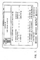
- Figure 4 illustrates a display generated for the next step in the current procedures in which the condition monitored by the current step has been verified at the time the step is entered.
- the prompts generated for the operator are labeled "CONTINUE” and "OVERRIDE”. If the operator selects "CONTINUE”, the system proceeds to the next applicable step. If, however, the operator selects "OVERRIDE”, the recommended action which would have been presented had the condition monitored by the current step not been verified is added to the display and the prompts are replaced by "ACTION COMPLETED” and "ACTION OVERRIDDEN". Such action would be taken for instance by the operator when other information available to him such as from the control board displays indicate that the condition is not verified. This could occur for example in the case of a faulty sensor. Thus, the system allows the operator to remain in control at all times.
- Step 12 shown in Fig. 4 is somewhat different from that in Figs. 2 and 3 in that the monitored parameter, SI RESET is at the level of the high-level statement that there are no supporting components or parameters. This does not affect execution of the step, however.
- the response processor 43 Upon receipt of an acceptable response from the operator, the response processor 43 activates the conditions logger 53 to record the contents of the current display exactly as the operator sees it, except that the operator response, such as, "OPERATOR COMPLETED ACTION” as shown in the partial display of Fig. 5, or "OPERATOR OVERRODE ACTION", et cetera, is recorded rather than the prompts.
- the operator response such as, "OPERATOR COMPLETED ACTION" as shown in the partial display of Fig. 5, or "OPERATOR OVERRODE ACTION", et cetera
- a permanent record is made of the time, the representation of the status tree status, any caution text which appears in the caution text window, the procedure title, the current step information, including the high-level statement and all plant status information as displayed for the user on the display, high-level results statements of the preceding two steps and high-level textual statements of the following two steps, and the operator's response to the system prompts.
- Recording is performed immediately following every acceptable operator response. Hence, the information stored by the recorder is that confirmed or rejected (override option) by the operator. Since an operator response is required to all prompts, recorded entries are not limited simply to step execution; they include all interaction with the parallel process functions as well.
- the conditions recording is accomplished by calling a subroutine at the end of every acceptable operator response.
- all the text which is displayed for the operator is stored in text buffers.
- the conditions recording subroutine When the conditions recording subroutine is called, it recreates the operator display using the information stored in the text buffers.
- a listing is built, line by line, by spacially locating the text strings and the text buffers so as to simulate the display as seen by the operator. As each line is built, it is written to an appropriate storage device 55 such as disc drive, a magnetic tape, or line printer.
- the improved recording feature is particularly valuable for post-situation review. Given some sort of accident from which procedures are used to recover, the review feature allows an expert to conveniently inspect and verify every action taken by the operator. This feature is also valuable when training new operators as the instructor can constructively comment on a new operator's recovery by reviewing the recorder listing.
- Another feature of the present invention is the ability to view the procedure as a whole.
- the earlier version of the system presented to the user the high-level results statements of a small number, preferably two, of the previous steps and high-level textual statements of the steps to be executed in the future, assuming normal order of execution.
- the present system has this capability as well, as seen from Figs. 2 through 4. It also enables the operator, on request, to scan the high-level textual statements of all of the steps of the current procedure. This can help the operators anticipate steps to be executed in the future. It can also help them understand the intent of a given procedure. This feature can be further used to re-execute a prior step.
- Scanning the high level textual statements of all of the steps of the current procedure is accomplished by accessing the library of steps stored in a file.
- the scanning option is presented to the operator at the completion of each step.
- the operator is presented with prompts which provide a choice between proceeding to the next step in the sequence or selecting another step by scanning forward or backward. If the "FORWARD/BACKWARD” button is touched, the operator is then presented with four options as shown in Fig. 7.
- the operator can scan forward or backward by touching the "FORWARD” or "BACKWARD” buttons respectively.
- the high level statement of the step selected appears in yellow above the touch buttons. In the example of Fig. 7, the operator has indexed back to step 11.
- step 11 is a prior step, the operator also has the option of re-executing the step by touching the "EXECUTE” touch button. This option is only available with a prior step so that the operator cannot easily jump over steps which have not yet been executed.
- step 11 is shown as the current step. While this display is very similar to that of Fig. 3, there is a noticeable difference. Namely, it can be seen that the two high-level statements of previous steps are for steps 11 and 12 which indicate to the operator where he was in the procedure when backward scanning was requested. The two subsequent steps presented are the steps 12 and 13 which follow the step which is being re-executed. Since the condition addressed by step 11 is verified, the operator is presented with the "CONTINUE" and "OVERRIDE" prompts, as would be presented for any verified step.
- Fig. 9 Upon selecting a response, the operator is presented with the option of continuing in sequence to the next step or returning to the main menu as shown in Fig. 9. If "RETURN TO MAIN MENU" is selected, the prompts of Fig. 6 would be presented again offering the choice to advance to the next step after the step from which the scan was initiated, step 13 in the example, or of scanning forward or backward again.
- the on-line review feature is called by an on-line review signal generated at the additional monitor 51 by a touch screen 52 or other input device. This feature permits the operator to review the previously executed steps on the additional monitor 51 simultaneously with the execution of the current step using the color monitor 27 so that operation of the system is not interrupted.
- the additional monitor 51 can be replaced by, or supplemented with, a printer, if a permanent copy of a past step or series of steps is desired.
- the on-line review feature is particularly useful during shift changes in the plant. The incoming operator need only use the review feature to learn the recent course of events and prepare for the upcoming shift. If the operator should forget something learned during the initial review, the listing can be reviewed again. This relieves both the exiting and incoming operators form having to commit a large amount of information to memory.
- the on-line review feature is accomplished by the digital computer 23 utilizing three additional files which may be referred to as files A, B, and C.
- file C be the summary file which contains a complete listing of all the conditions and operator actions. This file contains the same information as the conditions recording which is used strictly for archival purposes, as described above.
- Files A and B are temporary files used to gather the information generated in a manner similar to that used in the conditions recording subroutine. These files alternatively receive information from the subroutine and dump information to file C, the file which the operator reviews.
- file B is opened and becomes the receiving file for new information.
- File A is closed and appended at the end of file C.
- File C is then opened for review by the operator using a file review subroutine. When the operator has completed his review, file C is closed.
- the situation proceeds as decribed above with the roles of files A and B reversed. With this approach, file C always contains a complete listing of the current event conditions, which is available for operator examination.
- the present invention provides a more powerful computer-based system for assisting an operator in executing procedures for a complex process facility.
- the use of buffering allows for continuous plant data monitoring and continuous re-execution of procedure logic to provide feedback to the operator and verify operator action.
- the use of text strings in a conditions recording subroutine generates a more complete and understandable record of plant conditions during an event in the form of a copy of the screen as the operator sees it.
- the provision of an override feature allows the operator to maintain control of the procedure and assists in identifying and making a record of faulty sensors.
- the use of multiple files in a review subroutine provide the capability for on-line review of the plant conditions record.
- the use of a high level textual statement file and a scanning subroutine provide the ability to view the high level textual statements of the procedure steps.
Landscapes
- Engineering & Computer Science (AREA)
- Physics & Mathematics (AREA)
- General Engineering & Computer Science (AREA)
- High Energy & Nuclear Physics (AREA)
- Plasma & Fusion (AREA)
- Theoretical Computer Science (AREA)
- Emergency Management (AREA)
- Business, Economics & Management (AREA)
- Human Computer Interaction (AREA)
- General Physics & Mathematics (AREA)
- Testing And Monitoring For Control Systems (AREA)
- Safety Devices In Control Systems (AREA)
- Monitoring And Testing Of Nuclear Reactors (AREA)
Applications Claiming Priority (2)
| Application Number | Priority Date | Filing Date | Title |
|---|---|---|---|
| US07/020,285 US4815014A (en) | 1987-02-27 | 1987-02-27 | Machine assisted execution of process operating procedures |
| US20285 | 1987-02-27 |
Publications (3)
| Publication Number | Publication Date |
|---|---|
| EP0280553A2 true EP0280553A2 (de) | 1988-08-31 |
| EP0280553A3 EP0280553A3 (en) | 1989-11-08 |
| EP0280553B1 EP0280553B1 (de) | 1993-11-24 |
Family
ID=21797748
Family Applications (1)
| Application Number | Title | Priority Date | Filing Date |
|---|---|---|---|
| EP88301635A Expired - Lifetime EP0280553B1 (de) | 1987-02-27 | 1988-02-25 | Rechnerunterstützte Kontrolle von Prozessabläufen |
Country Status (5)
| Country | Link |
|---|---|
| US (1) | US4815014A (de) |
| EP (1) | EP0280553B1 (de) |
| JP (1) | JP2655605B2 (de) |
| KR (1) | KR950012938B1 (de) |
| ES (1) | ES2047542T3 (de) |
Cited By (10)
| Publication number | Priority date | Publication date | Assignee | Title |
|---|---|---|---|---|
| EP0371585A3 (de) * | 1988-11-28 | 1990-08-22 | The Babcock & Wilcox Company | Kernreaktor-Kühlsystemregelung |
| EP0441547A3 (en) * | 1990-02-05 | 1993-02-03 | Westinghouse Electric Corporation | Simulation of human performance of a process operation procedure |
| AU634341B2 (en) * | 1990-01-11 | 1993-02-18 | Kabushiki Kaisha Toshiba | Apparatus for supporting inspection of plant |
| WO1994003847A1 (de) * | 1992-08-01 | 1994-02-17 | Siemens Aktiengesellschaft | Verfahren und leittechnisches system zum steuern, überwachen und regeln insbesondere von komplexen industriellen prozessen, wie z.b. in einem kernkraftwerk |
| EP0566265A3 (en) * | 1992-04-13 | 1995-10-11 | Ibm | Computer pointing device with cleaning alarm |
| EP0716364A1 (de) * | 1994-12-06 | 1996-06-12 | Mitsubishi Denki Kabushiki Kaisha | Unterstützungssystem für Bedienungspersonal |
| CN102737742A (zh) * | 2011-04-02 | 2012-10-17 | 中广核工程有限公司 | 一种核电站事故工况下进入和退出数字化事故规程的方法 |
| CN104049578A (zh) * | 2013-03-12 | 2014-09-17 | 阿斯科动力科技公司 | 用于基础设施监测控制的方法和系统 |
| US8943125B2 (en) | 2010-10-20 | 2015-01-27 | Htc Corporation | Method of handling step execution result in software and application control management object |
| EP3139234A1 (de) * | 2015-09-02 | 2017-03-08 | Yokogawa Electric Corporation | Vorrichtungssystem, informationsverarbeitungsvorrichtung, informationsverarbeitungssystem und betriebsvorschlagsverfahren |
Families Citing this family (67)
| Publication number | Priority date | Publication date | Assignee | Title |
|---|---|---|---|---|
| US4902469A (en) * | 1986-05-05 | 1990-02-20 | Westinghouse Electric Corp. | Status tree monitoring and display system |
| US5062147A (en) * | 1987-04-27 | 1991-10-29 | Votek Systems Inc. | User programmable computer monitoring system |
| JPH0194404A (ja) * | 1987-10-06 | 1989-04-13 | Fanuc Ltd | Ncデータ作成方式 |
| GB2211965B (en) * | 1987-10-31 | 1992-05-06 | Rolls Royce Plc | Data processing systems |
| US5208745A (en) * | 1988-07-25 | 1993-05-04 | Electric Power Research Institute | Multimedia interface and method for computer system |
| JP2607663B2 (ja) * | 1989-01-31 | 1997-05-07 | 株式会社東芝 | プラント監視用対話装置 |
| US5027293A (en) * | 1989-02-03 | 1991-06-25 | Alliance Technical Services, Inc. | Method and apparatus for analyzing machine control systems |
| US5068080A (en) * | 1989-02-07 | 1991-11-26 | Westinghouse Electric Corp. | Operation state responsive automatic display selection system |
| US5276811A (en) * | 1989-06-30 | 1994-01-04 | Icom, Inc. | Method for emulating programmable logic controller by exchanging information between debug program which emulates I/O devices and ladder logic program |
| US5127099A (en) * | 1989-06-30 | 1992-06-30 | Icom, Inc. | Method and apparatus for securing access to a ladder logic programming and monitoring system |
| US5267145A (en) * | 1989-06-30 | 1993-11-30 | Icom, Inc. | Method and apparatus for program navigation and editing for ladder logic programs by determining which instructions reference a selected data element address |
| US5349518A (en) * | 1989-06-30 | 1994-09-20 | Icom, Inc. | Method and apparatus for symbolic ladder logic programming with automatic attachment of addresses |
| US5243511A (en) * | 1989-06-30 | 1993-09-07 | Icom, Inc. | Method and apparatus for block move re-addressing in ladder logic programs |
| US4991076A (en) * | 1989-06-30 | 1991-02-05 | Icom Inc. | Method and apparatus for creating custom displays for monitoring ladder logic programs |
| US5216624A (en) * | 1989-07-11 | 1993-06-01 | Hiroshi Kurita | Automated fossil-reflectance measurement apparatus and methods |
| US5167010A (en) * | 1989-08-03 | 1992-11-24 | Westinghouse Electric Corp. | Expert advice display processing system |
| JPH0392248A (ja) * | 1989-08-31 | 1991-04-17 | Toyoda Mach Works Ltd | 数値制御装置の操作順序表示装置 |
| US5267278A (en) * | 1989-11-02 | 1993-11-30 | Combustion Engineering, Inc. | Console for a nuclear control complex |
| US5267277A (en) * | 1989-11-02 | 1993-11-30 | Combustion Engineering, Inc. | Indicator system for advanced nuclear plant control complex |
| EP0439245A3 (en) * | 1990-01-23 | 1993-06-09 | Westinghouse Electric Corporation | Translator for computer aided generation of code for on-line interactive monitoring of the execution of complex operating procedures |
| US5089978A (en) * | 1990-02-09 | 1992-02-18 | Westinghouse Electric Corp. | Automatic plant state diagnosis system including a display selection system for selecting displays responsive to the diagnosis |
| US5321829A (en) * | 1990-07-20 | 1994-06-14 | Icom, Inc. | Graphical interfaces for monitoring ladder logic programs |
| US5155693A (en) * | 1990-09-05 | 1992-10-13 | Hewlett-Packard Company | Self documenting record of instrument activity and error messages stamped with date and time of occurrence |
| US5353238A (en) * | 1991-09-12 | 1994-10-04 | Cloos International Inc. | Welding robot diagnostic system and method of use thereof |
| AU2683192A (en) * | 1991-09-17 | 1993-04-27 | General Physics International Engineering & Simulation, Inc. | Real time analysis of power plant thermohydraulic phenomenon |
| US5253186A (en) * | 1991-10-07 | 1993-10-12 | Westinghouse Electric Corp. | Process facility monitoring method including transformation of sequential conditions into constraining conditions |
| US5351200A (en) * | 1991-11-22 | 1994-09-27 | Westinghouse Electric Corporation | Process facility monitor using fuzzy logic |
| CZ293613B6 (cs) * | 1992-01-17 | 2004-06-16 | Westinghouse Electric Corporation | Způsob monitorování chodu zařízení pomocí CPU |
| GB2263988B (en) * | 1992-02-04 | 1996-05-22 | Digital Equipment Corp | Work flow management system and method |
| US5361198A (en) * | 1992-04-03 | 1994-11-01 | Combustion Engineering, Inc. | Compact work station control room |
| JP3050348B2 (ja) * | 1992-04-17 | 2000-06-12 | インターナショナル・ビジネス・マシーンズ・コーポレイション | プロセス制御システムにおけるユーザ制御のための方法と装置 |
| JPH06331781A (ja) * | 1993-05-26 | 1994-12-02 | Toshiba Corp | プラント状態表示装置 |
| US5392226A (en) * | 1993-06-17 | 1995-02-21 | Icom, Inc. | Computer-implemented method and apparatus for monitoring statistical process control data |
| US5631825A (en) * | 1993-09-29 | 1997-05-20 | Dow Benelux N.V. | Operator station for manufacturing process control system |
| JP2829241B2 (ja) * | 1994-07-26 | 1998-11-25 | 三菱電機株式会社 | プラント支援装置 |
| JP3325737B2 (ja) * | 1995-03-09 | 2002-09-17 | 本田技研工業株式会社 | 品質管理データ処理装置 |
| DE69719269T2 (de) * | 1996-08-01 | 2003-10-30 | International Business Machines Corp., Armonk | Absicherung der Unteilbarkeit für eine Ansammlung von transaktionellen Arbeitsschritten in einem Arbeitsflussverwaltungssystem |
| US5905989A (en) * | 1996-11-27 | 1999-05-18 | Bently Nevada Corporation | Knowledge manager relying on a hierarchical default expert system: apparatus and method |
| US5838236A (en) * | 1997-05-27 | 1998-11-17 | Diversified Systems Incorporated | Manufacturing method and apparatus |
| WO1999024883A1 (en) * | 1997-11-07 | 1999-05-20 | Cbs Corporation | Method and system for automatically executing multiple procedures for a complex process facility |
| EP0997800B1 (de) * | 1998-10-29 | 2002-07-24 | Endress + Hauser GmbH + Co. KG | Gerät zur Verwendung in einem industriellen Prozess und Anlage mit solchen Geräten sowie Verfahren zum Simulieren des Betriebs einer solchen Anlage |
| US6678585B1 (en) * | 1999-09-28 | 2004-01-13 | Pavilion Technologies, Inc. | Method and apparatus for maximizing power usage in a power plant |
| US6934696B1 (en) | 2000-09-15 | 2005-08-23 | Bently Nevada, Llc | Custom rule system and method for expert systems |
| US7085607B2 (en) * | 2001-09-21 | 2006-08-01 | Westinghouse Electric Co, Llc | Control system display for monitoring a complex process |
| DE10203653A1 (de) * | 2002-01-30 | 2003-07-31 | Deere & Co | Arbeitsmaschine mit tragbarem Bediengerät |
| US6725137B2 (en) * | 2002-04-03 | 2004-04-20 | Honeywell International Inc. | Method and apparatus using historical data to associate deferral procedures and fault models |
| US20050125079A1 (en) * | 2003-12-08 | 2005-06-09 | Schreder James M. | Interactive instructions in sequential control modules in controllers |
| US7295944B2 (en) * | 2004-02-25 | 2007-11-13 | Analysis And Measurement Services Corporation | Cross-calibration of plant instruments with computer data |
| DE102004055107A1 (de) * | 2004-11-15 | 2006-06-01 | Abb Patent Gmbh | System und Verfahren zur Status- und Fortschrittskontrolle eines technischen Prozesses oder eines technischen Projektes |
| US8115138B2 (en) * | 2005-03-15 | 2012-02-14 | Lincoln Global, Inc. | Comprehensive identification and designation of welding procedures |
| US20080220384A1 (en) * | 2005-04-15 | 2008-09-11 | Rh Peterson Company | Air quality sensor/interruptor |
| US20070016456A1 (en) * | 2005-07-12 | 2007-01-18 | International Business Machines Corporation | System, method and program product for reporting status of contract performance or a process |
| US7813817B2 (en) * | 2006-05-19 | 2010-10-12 | Westinghouse Electric Co Llc | Computerized procedures system |
| DE102006034681B4 (de) * | 2006-07-24 | 2013-02-07 | Areva Np Gmbh | Verfahren zur Stabilisierung der Zykluszeit eines zyklischen Prozesses in einem Automatisierungssystem sowie Automatisierungssystem |
| DE102007038722A1 (de) * | 2007-08-16 | 2009-02-26 | Siemens Ag | Verfahren zum Auslösen von Aktionen einer Maschine durch sichere Eingabeelemente |
| CN100576365C (zh) * | 2007-09-14 | 2009-12-30 | 大亚湾核电运营管理有限责任公司 | 一种核电机组的控制系统及其监控方法和子系统 |
| US8656301B2 (en) * | 2009-04-30 | 2014-02-18 | Epsis As | Information display system |
| US20150049851A1 (en) * | 2012-03-26 | 2015-02-19 | Mitsubishi Heavy Industries, Ltd. | Central control device of nuclear power plant, plant operation support device, and plant operation support method |
| JP6596261B2 (ja) * | 2015-08-19 | 2019-10-23 | 三菱重工業株式会社 | 原子力プラントの電子手順書表示装置、安全系制御監視システム、及び運転監視システム |
| JP7227002B2 (ja) | 2015-10-09 | 2023-02-21 | フィッシャー-ローズマウント システムズ,インコーポレイテッド | プロセス制御システムの安全イベントの視覚化を経時的に提供するためのシステム及び方法 |
| US12164275B2 (en) * | 2015-10-09 | 2024-12-10 | Fisher-Rosemount Systems, Inc. | System and method for providing a visualization of safety events of a process control system over time |
| FR3045179B1 (fr) * | 2015-12-15 | 2018-01-26 | Areva Np | Dispositif electronique et procede de gestion de l'affichage de donnees pour le pilotage d'une centrale nucleaire, systeme de pilotage et produit programme d'ordinateur associes |
| US20190318624A1 (en) * | 2016-10-21 | 2019-10-17 | Dot Incorporation | Boarding information guiding system and method, and procedure management device and method |
| US12347333B2 (en) | 2016-10-21 | 2025-07-01 | Dot Incorporation | Boarding information guiding system and method, and procedure management device and method |
| CA3053281A1 (en) * | 2017-02-21 | 2018-08-30 | Centre For Commercialization Of Regenerative Medicine | Method and system for electronically monitoring and recording a process in a clean space |
| KR102650516B1 (ko) * | 2017-06-23 | 2024-03-21 | 캔두 에너지 인코포레이티드 | 원자로 툴링을 위한 통신 시스템 및 방법 |
| US11126789B2 (en) | 2017-12-21 | 2021-09-21 | Battelle Energy Alliance, Llc | Method to convert a written procedure to structured data, and related systems and methods |
Family Cites Families (5)
| Publication number | Priority date | Publication date | Assignee | Title |
|---|---|---|---|---|
| US4552718A (en) * | 1982-07-01 | 1985-11-12 | Westinghouse Electric Corp. | Method and apparatus for on-line monitoring of the operation of a complex non-linear process control system |
| US4632802A (en) * | 1982-09-16 | 1986-12-30 | Combustion Engineering, Inc. | Nuclear plant safety evaluation system |
| US4488258A (en) * | 1982-09-20 | 1984-12-11 | Allen-Bradley | Programmable controller with control program comments |
| JPS5962947A (ja) * | 1982-10-01 | 1984-04-10 | Fanuc Ltd | 数値制御方式 |
| US4803039A (en) * | 1986-02-03 | 1989-02-07 | Westinghouse Electric Corp. | On line interactive monitoring of the execution of process operating procedures |
-
1987
- 1987-02-27 US US07/020,285 patent/US4815014A/en not_active Expired - Lifetime
-
1988
- 1988-02-15 KR KR1019880001488A patent/KR950012938B1/ko not_active Expired - Fee Related
- 1988-02-25 ES ES88301635T patent/ES2047542T3/es not_active Expired - Lifetime
- 1988-02-25 EP EP88301635A patent/EP0280553B1/de not_active Expired - Lifetime
- 1988-02-26 JP JP63042405A patent/JP2655605B2/ja not_active Expired - Lifetime
Cited By (13)
| Publication number | Priority date | Publication date | Assignee | Title |
|---|---|---|---|---|
| EP0371585A3 (de) * | 1988-11-28 | 1990-08-22 | The Babcock & Wilcox Company | Kernreaktor-Kühlsystemregelung |
| AU634341B2 (en) * | 1990-01-11 | 1993-02-18 | Kabushiki Kaisha Toshiba | Apparatus for supporting inspection of plant |
| EP0441547A3 (en) * | 1990-02-05 | 1993-02-03 | Westinghouse Electric Corporation | Simulation of human performance of a process operation procedure |
| EP0566265A3 (en) * | 1992-04-13 | 1995-10-11 | Ibm | Computer pointing device with cleaning alarm |
| US5634039A (en) * | 1992-08-01 | 1997-05-27 | Siemens Aktiengesellschaft | Method and management system for controlling, monitoring and regulating complex industrial processes in particular, such as in a nuclear power plant |
| WO1994003847A1 (de) * | 1992-08-01 | 1994-02-17 | Siemens Aktiengesellschaft | Verfahren und leittechnisches system zum steuern, überwachen und regeln insbesondere von komplexen industriellen prozessen, wie z.b. in einem kernkraftwerk |
| EP0716364A1 (de) * | 1994-12-06 | 1996-06-12 | Mitsubishi Denki Kabushiki Kaisha | Unterstützungssystem für Bedienungspersonal |
| US5805465A (en) * | 1994-12-06 | 1998-09-08 | Mitsubishi Denki Kabushiki Kaisha | Operator support system |
| US8943125B2 (en) | 2010-10-20 | 2015-01-27 | Htc Corporation | Method of handling step execution result in software and application control management object |
| CN102737742A (zh) * | 2011-04-02 | 2012-10-17 | 中广核工程有限公司 | 一种核电站事故工况下进入和退出数字化事故规程的方法 |
| CN104049578A (zh) * | 2013-03-12 | 2014-09-17 | 阿斯科动力科技公司 | 用于基础设施监测控制的方法和系统 |
| US10712735B2 (en) | 2013-03-12 | 2020-07-14 | Asco Power Technologies, L.P. | Methods and systems for infrastructure-monitoring control |
| EP3139234A1 (de) * | 2015-09-02 | 2017-03-08 | Yokogawa Electric Corporation | Vorrichtungssystem, informationsverarbeitungsvorrichtung, informationsverarbeitungssystem und betriebsvorschlagsverfahren |
Also Published As
| Publication number | Publication date |
|---|---|
| KR880010433A (ko) | 1988-10-08 |
| US4815014A (en) | 1989-03-21 |
| EP0280553B1 (de) | 1993-11-24 |
| EP0280553A3 (en) | 1989-11-08 |
| ES2047542T3 (es) | 1994-03-01 |
| JP2655605B2 (ja) | 1997-09-24 |
| KR950012938B1 (ko) | 1995-10-23 |
| JPS63223904A (ja) | 1988-09-19 |
Similar Documents
| Publication | Publication Date | Title |
|---|---|---|
| EP0280553B1 (de) | Rechnerunterstützte Kontrolle von Prozessabläufen | |
| US4803039A (en) | On line interactive monitoring of the execution of process operating procedures | |
| US5121318A (en) | On-line plant operating procedure guidance system | |
| US4957690A (en) | System and method for monitoring and control of safety-related components of a nuclear power plant | |
| EP1114361B1 (de) | Verfahren und vorrichtung zur betriebsueberwachung eines industriellen prozesses | |
| Kang et al. | Concept of an intelligent operator support system for initial emergency responses in nuclear power plants | |
| AU2001240773A1 (en) | System and method for monitoring a control process in a process plant | |
| JPH0836682A (ja) | プラント監視装置および監視方法 | |
| EP0245039B1 (de) | Zustandsbaumüberwachungs- und -anzeigesystem | |
| Chang et al. | Development of an advanced human–machine interface for next generation nuclear power plants | |
| GB2448894A (en) | Computer-aided fault tracking for industrial plant providing instructions and countdown | |
| JPH07121231A (ja) | モニタリング方法およびモニタリングシステム | |
| JP2646115B2 (ja) | 試験監視制御装置及び方法 | |
| JPH0289101A (ja) | プロセスプラント緊急時支援システム | |
| JPH0584907B2 (de) | ||
| Lipner et al. | A Computerized System for Improved Management and Execution of Plant Procedures | |
| Humble et al. | Use of computer aids including expert systems to enhance diagnosis of NPP safety status and operator response. VDU displays in accidents-Interact | |
| Fujita et al. | Designing a knowledge-based operator support system for practical applications | |
| JPH025280B2 (de) | ||
| Lupton et al. | A framework for operator support systems for CANDU | |
| Uhrig | Use of artificial intelligence to enhance the safety of nuclear power plants | |
| Nowicki et al. | On-line data acquisition and processing system for the HTGR | |
| Richelle et al. | Westinghouse Computer-Based Operator Support Systems | |
| JPS5957193A (ja) | 制御棒自動操作装置 | |
| Oudiz et al. | Improvement of incidental recovery performances on console by the use of synthesis images in the monitoring phase |
Legal Events
| Date | Code | Title | Description |
|---|---|---|---|
| PUAI | Public reference made under article 153(3) epc to a published international application that has entered the european phase |
Free format text: ORIGINAL CODE: 0009012 |
|
| AK | Designated contracting states |
Kind code of ref document: A2 Designated state(s): BE CH ES FR GB IT LI |
|
| PUAL | Search report despatched |
Free format text: ORIGINAL CODE: 0009013 |
|
| AK | Designated contracting states |
Kind code of ref document: A3 Designated state(s): BE CH ES FR GB IT LI |
|
| 17P | Request for examination filed |
Effective date: 19900426 |
|
| 17Q | First examination report despatched |
Effective date: 19920811 |
|
| GRAA | (expected) grant |
Free format text: ORIGINAL CODE: 0009210 |
|
| AK | Designated contracting states |
Kind code of ref document: B1 Designated state(s): BE CH ES FR GB IT LI |
|
| ET | Fr: translation filed | ||
| ITF | It: translation for a ep patent filed | ||
| REG | Reference to a national code |
Ref country code: ES Ref legal event code: FG2A Ref document number: 2047542 Country of ref document: ES Kind code of ref document: T3 |
|
| PLBE | No opposition filed within time limit |
Free format text: ORIGINAL CODE: 0009261 |
|
| STAA | Information on the status of an ep patent application or granted ep patent |
Free format text: STATUS: NO OPPOSITION FILED WITHIN TIME LIMIT |
|
| 26N | No opposition filed | ||
| REG | Reference to a national code |
Ref country code: GB Ref legal event code: IF02 |
|
| PGFP | Annual fee paid to national office [announced via postgrant information from national office to epo] |
Ref country code: ES Payment date: 20020212 Year of fee payment: 15 |
|
| PGFP | Annual fee paid to national office [announced via postgrant information from national office to epo] |
Ref country code: BE Payment date: 20020318 Year of fee payment: 15 |
|
| PGFP | Annual fee paid to national office [announced via postgrant information from national office to epo] |
Ref country code: CH Payment date: 20020325 Year of fee payment: 15 |
|
| PGFP | Annual fee paid to national office [announced via postgrant information from national office to epo] |
Ref country code: GB Payment date: 20030106 Year of fee payment: 16 |
|
| PG25 | Lapsed in a contracting state [announced via postgrant information from national office to epo] |
Ref country code: ES Free format text: LAPSE BECAUSE OF NON-PAYMENT OF DUE FEES Effective date: 20030226 |
|
| PG25 | Lapsed in a contracting state [announced via postgrant information from national office to epo] |
Ref country code: LI Free format text: LAPSE BECAUSE OF NON-PAYMENT OF DUE FEES Effective date: 20030228 Ref country code: BE Free format text: LAPSE BECAUSE OF NON-PAYMENT OF DUE FEES Effective date: 20030228 Ref country code: CH Free format text: LAPSE BECAUSE OF NON-PAYMENT OF DUE FEES Effective date: 20030228 |
|
| REG | Reference to a national code |
Ref country code: CH Ref legal event code: PL |
|
| PG25 | Lapsed in a contracting state [announced via postgrant information from national office to epo] |
Ref country code: GB Free format text: LAPSE BECAUSE OF NON-PAYMENT OF DUE FEES Effective date: 20040225 |
|
| REG | Reference to a national code |
Ref country code: ES Ref legal event code: FD2A Effective date: 20030226 |
|
| GBPC | Gb: european patent ceased through non-payment of renewal fee |
Effective date: 20040225 |
|
| PG25 | Lapsed in a contracting state [announced via postgrant information from national office to epo] |
Ref country code: IT Free format text: LAPSE BECAUSE OF NON-PAYMENT OF DUE FEES Effective date: 20050225 |
|
| PGFP | Annual fee paid to national office [announced via postgrant information from national office to epo] |
Ref country code: FR Payment date: 20070201 Year of fee payment: 20 |