EP0280619A2 - Vorrichtung zum Zusammensetzen von Zuschnitten, insbesondere im Hinblick auf die Herstellung von Verpackungen - Google Patents
Vorrichtung zum Zusammensetzen von Zuschnitten, insbesondere im Hinblick auf die Herstellung von Verpackungen Download PDFInfo
- Publication number
- EP0280619A2 EP0280619A2 EP88400390A EP88400390A EP0280619A2 EP 0280619 A2 EP0280619 A2 EP 0280619A2 EP 88400390 A EP88400390 A EP 88400390A EP 88400390 A EP88400390 A EP 88400390A EP 0280619 A2 EP0280619 A2 EP 0280619A2
- Authority
- EP
- European Patent Office
- Prior art keywords
- conveyor
- main conveyor
- series
- cutouts
- intended
- Prior art date
- Legal status (The legal status is an assumption and is not a legal conclusion. Google has not performed a legal analysis and makes no representation as to the accuracy of the status listed.)
- Withdrawn
Links
Images



Classifications
-
- B—PERFORMING OPERATIONS; TRANSPORTING
- B65—CONVEYING; PACKING; STORING; HANDLING THIN OR FILAMENTARY MATERIAL
- B65H—HANDLING THIN OR FILAMENTARY MATERIAL, e.g. SHEETS, WEBS, CABLES
- B65H3/00—Separating articles from piles
- B65H3/08—Separating articles from piles using pneumatic force
- B65H3/12—Suction bands, belts, or tables moving relatively to the pile
- B65H3/122—Suction tables
-
- B—PERFORMING OPERATIONS; TRANSPORTING
- B31—MAKING ARTICLES OF PAPER, CARDBOARD OR MATERIAL WORKED IN A MANNER ANALOGOUS TO PAPER; WORKING PAPER, CARDBOARD OR MATERIAL WORKED IN A MANNER ANALOGOUS TO PAPER
- B31B—MAKING CONTAINERS OF PAPER, CARDBOARD OR MATERIAL WORKED IN A MANNER ANALOGOUS TO PAPER
- B31B50/00—Making rigid or semi-rigid containers, e.g. boxes or cartons
- B31B50/02—Feeding or positioning sheets, blanks or webs
- B31B50/04—Feeding sheets or blanks
- B31B50/042—Feeding sheets or blanks using rolls, belts or chains
-
- B—PERFORMING OPERATIONS; TRANSPORTING
- B31—MAKING ARTICLES OF PAPER, CARDBOARD OR MATERIAL WORKED IN A MANNER ANALOGOUS TO PAPER; WORKING PAPER, CARDBOARD OR MATERIAL WORKED IN A MANNER ANALOGOUS TO PAPER
- B31B—MAKING CONTAINERS OF PAPER, CARDBOARD OR MATERIAL WORKED IN A MANNER ANALOGOUS TO PAPER
- B31B50/00—Making rigid or semi-rigid containers, e.g. boxes or cartons
- B31B50/02—Feeding or positioning sheets, blanks or webs
- B31B50/04—Feeding sheets or blanks
- B31B50/07—Feeding sheets or blanks by air pressure or suction
-
- B—PERFORMING OPERATIONS; TRANSPORTING
- B31—MAKING ARTICLES OF PAPER, CARDBOARD OR MATERIAL WORKED IN A MANNER ANALOGOUS TO PAPER; WORKING PAPER, CARDBOARD OR MATERIAL WORKED IN A MANNER ANALOGOUS TO PAPER
- B31B—MAKING CONTAINERS OF PAPER, CARDBOARD OR MATERIAL WORKED IN A MANNER ANALOGOUS TO PAPER
- B31B2105/00—Rigid or semi-rigid containers made by assembling separate sheets, blanks or webs
-
- B—PERFORMING OPERATIONS; TRANSPORTING
- B31—MAKING ARTICLES OF PAPER, CARDBOARD OR MATERIAL WORKED IN A MANNER ANALOGOUS TO PAPER; WORKING PAPER, CARDBOARD OR MATERIAL WORKED IN A MANNER ANALOGOUS TO PAPER
- B31B—MAKING CONTAINERS OF PAPER, CARDBOARD OR MATERIAL WORKED IN A MANNER ANALOGOUS TO PAPER
- B31B2120/00—Construction of rigid or semi-rigid containers
-
- B—PERFORMING OPERATIONS; TRANSPORTING
- B31—MAKING ARTICLES OF PAPER, CARDBOARD OR MATERIAL WORKED IN A MANNER ANALOGOUS TO PAPER; WORKING PAPER, CARDBOARD OR MATERIAL WORKED IN A MANNER ANALOGOUS TO PAPER
- B31B—MAKING CONTAINERS OF PAPER, CARDBOARD OR MATERIAL WORKED IN A MANNER ANALOGOUS TO PAPER
- B31B50/00—Making rigid or semi-rigid containers, e.g. boxes or cartons
- B31B50/02—Feeding or positioning sheets, blanks or webs
-
- B—PERFORMING OPERATIONS; TRANSPORTING
- B31—MAKING ARTICLES OF PAPER, CARDBOARD OR MATERIAL WORKED IN A MANNER ANALOGOUS TO PAPER; WORKING PAPER, CARDBOARD OR MATERIAL WORKED IN A MANNER ANALOGOUS TO PAPER
- B31B—MAKING CONTAINERS OF PAPER, CARDBOARD OR MATERIAL WORKED IN A MANNER ANALOGOUS TO PAPER
- B31B50/00—Making rigid or semi-rigid containers, e.g. boxes or cartons
- B31B50/02—Feeding or positioning sheets, blanks or webs
- B31B50/022—Holders for feeding or positioning blanks or webs
- B31B50/024—Rotating holders, e.g. star wheels, drums
-
- B—PERFORMING OPERATIONS; TRANSPORTING
- B31—MAKING ARTICLES OF PAPER, CARDBOARD OR MATERIAL WORKED IN A MANNER ANALOGOUS TO PAPER; WORKING PAPER, CARDBOARD OR MATERIAL WORKED IN A MANNER ANALOGOUS TO PAPER
- B31B—MAKING CONTAINERS OF PAPER, CARDBOARD OR MATERIAL WORKED IN A MANNER ANALOGOUS TO PAPER
- B31B50/00—Making rigid or semi-rigid containers, e.g. boxes or cartons
- B31B50/02—Feeding or positioning sheets, blanks or webs
- B31B50/04—Feeding sheets or blanks
- B31B50/06—Feeding sheets or blanks from stacks
- B31B50/066—Feeding sheets or blanks from stacks from above a magazine
Definitions
- the present invention relates to a device for assembling blanks, in particular for producing packaging boxes, of the type comprising a series of work stations distributed around a main vacuum conveyor, the work stations being in particular made up of feeders equipped with a battery charger and a conveyor, and gluing machines of the type comprising a glue supply and a mobile carrying carriage.
- Patent No. 82 04179 of the Applicant relates in particular to an automatic device comprising a horizontal circular plate movable around a vertical axis, a series of suction boxes mounted on said plate, connected to a source of vacuum and intended to receive the blanks to thus assemble a series of work stations arranged around the tray in predetermined angular positions.
- the cuts are deposited on the suction box and are held in position by said suction.
- the blank feed stations comprise a frame disposed radially with respect to the plate, and which extends partially above the latter, a plate mounted movable in vertical direction on said frame, and which is intended to receive said separate cutouts, a frame mounted movable on radial rails provided at the upper end of said frame and which can be brought from a first radial position in which it extends above said plate in a second radial position, in which it extends above a suction box of said tray, a series of suction cups mounted on crosspieces of said movable frame and which are connected to a vacuum source, control means making it possible to bring said frame or said sleepers in a low position for gripping and depositing the cutouts and in a high position for the translational movement of said frame from one of said positions to the other.
- the object of the present invention is to remedy these drawbacks by producing an automatic device for the assembly of cutouts, which is modular, rapid and of very high precision.
- the device according to the present invention relates more specifically to a device for assembling blanks, in particular for the production of assembly boxes, of the type comprising a series of work stations distributed around a main linear vacuum conveyor, comprising longitudinal vacuum boxes, the work stations being in particular made up of feeders provided with a battery charger and a conveyor, and gluers of the type comprising a glue supply and a mobile pad-holding carriage, said conveyor main comprising at least one toothed belt movable above a series of vacuum boxes.
- the toothed belts are advantageously guided at regular intervals by slides of a depth slightly less than the thickness of said toothed belts.
- the toothed belts are driven by a motor of the stepping type with numerical control.
- the main conveyor comprises at the outlet end an unloading area provided with a movable carriage supporting at least one suction box moving transversely from a position above the main conveyor to a position at - above the unloading area.
- the suction box has an air outlet coming in cooperation with a fixed flap when the mobile carriage arrives vertically from the unloading area.
- said main conveyor further comprises at least one shape recognition system intended to verify the conformity of the parts with respect to a reference.
- the main conveyor with toothed belts allows very precise positioning of the cutouts and the positioning of the positioning of the second cutout relative to the first cutout is made by detecting the displacement of the main conveyor. This detection is done by counting pulses when the toothed belts are driven by a stepping type motor.
- the role of the pattern recognition system is not to enslave the movement of the main transporter, but to cause non-passage to workstations according to non-standard parts, as well as their rejection.
- the present invention also relates to a device for assembling blanks comprising a blank feed station consisting of a battery charger comprising a lifting frame supporting a removable rake, and a fixed fixed platform made of a comb whose intervals allow the introduction of said rake.
- the battery charger has a fixed lower plate provided with movable slides intended to hold the separating plates, ensuring the lateral positioning of the cut-out stacks.
- the positioning of the top of the cut pile is carried out by a vibrating bar provided with joggers.
- the feeder comprises, in addition to the battery charger, a conveyor consisting of a mobile carriage moved horizontally by a ball screw system, said mobile carriage supporting a vertically movable plate, provided with suction cups connected on the one hand to a vacuum pump , and an air injection system on the other hand.
- said carriage supports a double plate comprising two series of suction cups.
- the feeder consists of two battery chargers arranged symmetrically on either side of the main conveyor, and a conveyor comprising a carriage moved horizontally by a ball screw system, said carriage supporting a double plate moved vertically by jacks, said double plate being provided with two sets of suction cups, one of the series of suction cups recovering the set of cutouts present on the tops of the batteries of the first charger, while the other series of suction cups discharges the leaves coming from the second loader, on the conveyor.
- At least one of the stations consists of a gluing machine comprising a glue supply system provided with roller supports and several rollers, a peristatic pump bringing the glue between said rollers by means of a pipe, and a mobile pad-holding carriage provided with a honeycomb grid allowing the adaptation of an applicator pad corresponding to the sizing surface, said honeycomb grid being crossed by stripping pins.
- the glue supply system comprises in in addition to a water inlet at the level of said rollers, and a tank for discharging the cleaning water.
- rollers are mounted on the axis support movable laterally, the pressure of the rollers between them being ensured by pressure springs.
- the speed of the pad is advantageously greater than the speed of the roller at the edges of the gluing zone.
- the device according to the present invention is particularly suitable for producing packaging boxes made up of different parts made of cardboard, plastic, wood, metal or any other material.
- the movement of said parts using a main conveyor of the toothed belt type allows very high precision in the relative positioning of said parts.
- the device according to the present invention allows the production of boxes requiring to date manual assembly, a competitive production cost.
- the device according to the present invention comprises a frame supporting a horizontal linear main conveyor provided with fixed and longitudinal vacuum chambers (1) opening on their upper face on a drive means consisting of notched belts (2) arranged horizontally.
- the work stations distributed along said linear main conveyor allow the deposition and positioning of blanks as well as treatments such as the gluing of certain parts of said blanks.
- the cuts are made up of sheets of any shape, with a thickness of between ten microns and a few centimeters.
- the work stations consist of at least a first feeder (8) intended to position a first blank on the main linear conveyor.
- Said feeder (8) comprises at least one battery charger (66) and a conveyor (9) retrieving the cuts on the feeder (8) and depositing them on the reception area of the first cuts (68) during a phase of stop of the linear main conveyor.
- the scrolling of the notched belts (2) causes a displacement of the first cut to the second work station.
- the precision of the movement comes from the adhesion of the cutout on the toothed belts, due to the vacuum created by the vacuum boxes (1) and by the qualities of adhesion linked to the material constituting said toothed belts.
- the second work station (10) is constituted by a gluing machine intended to deposit a film of glue in certain places of the first cut.
- the axial precision that is to say parallel to the toothed belts (2), is ensured by the precision of the displacement of said toothed belts, and the transverse precision, by the reproducibility of the positioning of the size.
- a third workstation (11) is constituted by a second feeder intended to position a second cutout, or piece, on the first glued cutout.
- a last work station (12) constitutes the reception of the assembled blanks.
- Shape recognition means (28), arranged between the work stations, are intended to verify the conformity of the cuts and their processing. In the event of non-compliance, they block the operation of the following stations and cause rejection at the end of the main transporter.
- the device according to the present invention comprises a main vacuum conveyor consisting of a series of vacuum boxes (1) and toothed belts (2).
- the toothed belts (2) are positioned and guided at regular intervals by means of slides (3).
- the two parallel vertical edges (4) and (5) of the slides (3) are spaced apart by a width corresponding substantially to the width of the toothed belts (2) so as to allow the said toothed belts (2) to run without play.
- the height of the vertical parallel edges (4) and (5) is slightly less than the thickness of the toothed belts (2).
- the spacing between two slides (3) is chosen so as to be small compared to the dimension of the cutouts. This spacing will advantageously be less than one tenth of the smallest dimension of said cuts.
- the vacuum provided by the vacuum boxes (1) arranged under the said slides (3) allows the blanks deposited on the main conveyor to be placed against the toothed belts (2).
- the toothed belts (2) are made of synthetic material, in particular by neoprene, having reduced slip and very low elongation.
- the mobile pedestals are juxtaposed so as to limit the discontinuity of depression. They are connected to a vacuum source.
- the toothed belts (2) are driven by a drum moved by a motor (7).
- the motor (7) will be chosen of the stepping type and the drum (6) connected to an incremental encoder in order to allow precise digital control.
- the pitch will be chosen so as to correspond to a displacement of the toothed belts (2) of between 0.02 mm and 3 mm, and preferably one tenth of a millimeter.
- the device according to the invention comprises on either side of the main conveyor work stations (8), (9), (10), (11) and (12).
- the main conveyor ensures the movement from one station to another of the cutouts and assembled parts as well as the correct positioning at each workstation.
- the vacuum boxes (1) are connected to a suction system providing a partial vacuum in said boxes (1).
- the main suction conveyor comprises between 10 and 13 series of slides (3) and toothed belts (2) and advantageously 16 slides (3) and 16 toothed belts (2).
- the main conveyor comprises at the outlet end a reception area (13) as well as an unloading area (14).
- a mobile carriage (15) supports at least one suction box (16) and preferably a second suction box (17).
- the suction boxes (16), (17) are provided with an integrated vacuum system, for example an electric fan.
- Each suction box (16), (17) has an air outlet (18), (19) disposed on its upper part.
- the suction boxes (16), (17) are moved vertically by jacks (20) integral with the mobile carriage (15).
- the mobile carriage (15) is moved horizontally by a ball screw system (21), or any other identical means making it possible to move said mobile carriage (15) transversely relative to the main conveyor.
- the function of the suction boxes (16), (17) is to recover the boxes assembled at the end of the conveyor main, when they arrive on the reception area (13) and bring them to the unloading area (14) of a transporter (22) which takes them to a storage area for example.
- a second rejection conveyor (23) is arranged opposite the unloading area intended to carry the non-conforming parts into a rejection area (24).
- the suction boxes (16), (17) provide a second pressing function for the laminated cutouts.
- the underside (25) of the suction boxes (16), (17) consists of a perforated grid.
- the assembled boxes are held by vacuum on the suction boxes (16), (17) during transport between the receiving area (13) and the unloading area (14) or the rejection area (24).
- a fixed shutter (26) closes the air outlet (18). Closing the air outlet (18) lowers the vacuum inside the suction box (16) and causes the fall of the assembled box retained by said suction box (16).
- the assembled box is then taken by the transporter (22) to a storage area. Closing the air outlet (18) also causes turbulence creating a slight overpressure inside the box, thus improving the removal of the assembled box.
- the defective boxes are discharged onto the conveyor (23) by the suction box (17).
- the device comprises a system for acquiring the tolerances of each of the boxes produced for the purpose of stastics.
- the acquisition of the characteristics of a new series of parts is done by automatic learning in position by the shape recognition system.
- the device stops the chain in order to allow adjustment of the defective workstation.
- the device according to the present invention further comprises at least one feeder intended to supply the main conveyor with parts or cuts.
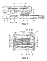
- the feeder consists of at least one battery charger shown schematically in Figure 3, and a conveyor shown schematically in Figure 4.
- the battery charger brings a series of cutouts opposite the conveyor so that it can take them.
- the battery charger comprises a frame (29) having guide means, and a lifting frame. Linear guidance can be achieved by a roller (30) resting on a vertical profile (31) mounted on the frame (29).
- the lifting frame is in the form of a rectangular frame (32) moved vertically using cables (33) or jacks.
- cables 33) or jacks.
- the digital control allows vertical positioning of the stack (35) with an accuracy of the order of a tenth of a micron.
- the internal dimensions of said frame (32) are greater than the dimensions of a fixed lower plate (36).
- the frame (32) supports a rake (37) consisting of a horizontal profiled bar (38) and substantially parallel to the main conveyor.
- Said profiled bar (38) is made of aluminum, and comprises a series of teeth (39) horizontal and perpendicular to the axis of the main conveyor.
- the teeth are made of polyester.
- Said rake (37) rests on the frame (32) on the two segments parallel to the main conveyor via these teeth (39), the profiled bar (38) projecting beyond said frame (32).
- the battery charger further comprises an optical detector (43) controlling the elevation movement of the lifting frame (32) so as to ensure a constant level at the top of the battery (35).
- an optical detector (43) controlling the elevation movement of the lifting frame (32) so as to ensure a constant level at the top of the battery (35).
- the lower part of the battery charger comprises a fixed lower plate (36) with skeleton consisting of a comb (44) whose intervals allow the introduction of the teeth (39) of the rake (37).
- the lifting frame (32) returns to the low position, that is to say to a level lower than the fixed lower plate (36) .
- the rake (37) is then reintroduced into the space remaining between the skeleton profiles of the comb (44), and the lower part of the new piles deposited on the tray.
- the battery charger is then ready for a new operating cycle.
- the lifting frame (32) is again moved vertically, and when the two parts parallel to the main conveyor come into contact with the teeth (39), said lifting frame (32) ensures the rise of the rake (37), and therefore of the new battery (35).
- the lower plate (36) further comprises slides (45) allowing the maintenance of separating plates (46), (47) ensuring the lateral positioning of the stacks (35).
- the positioning of the slides (45) can be adjusted laterally quickly so that the battery charger can be adapted to the dimensions of the cutouts or parts making up the battery (35).
- the separating plates (46), (47) are held in their upper part by adjustable indexes (48) mounted on an upper graduated rule (49), as well as in their lower part by a slide (45) mounted on lower twin graduated rulers (50) and (51).
- the positioning of the indexes (48) and of the slides (45) can be prepared on a second set of upper rulers (49) and lower twin graduated rulers (50) and (51). Their replacement can be ensured very quickly by dismantling the first set of rulers and replacement by the second set prepared outside the post.
- the separator plates (46) are then replaced.
- the separator plates (46) have at their upper part tabs (52) of small thickness providing flexible blocking of the upper sheets of the stack (35).
- the indexes (48) of the upper graduated rule (49) also include a flexible tab (53) slightly retaining the last sheet of the stack.
- the cleats (52) are made in the form of a small piece of rubber.
- the feeder further comprises a conveyor shown schematically in FIG. 4.
- the pieces or cutouts present at the top of the stack (35) are removed by a conveyor consisting of a carriage mobile (54) moved horizontally by a ball screw system (55) controlled by a DC motor (56) with digital control controlled by an incremental angular encoder (57).
- the mobile carriage (54) supports a plate (58).
- Said plate (58) is vertically movable by means of pneumatic or hydraulic cylinders (59).
- This plate (58) comprises suction cup supports (60) adjustable laterally according to the dimensions of the parts or cutouts.
- the suction cups (61) are connected to a vacuum pump (62) via a reserve (63) and a vacuum valve (64) controlling the vacuum, as well as to a source of compressed air via an injection valve (65).
- the operation is as follows: the part (s) or cutouts present at the top of the stacks (35) are slightly held by the flexible tongues (53) and the cleats (52).
- the suction cups (61) are brought by the mobile carriage (54) to the veticale of the battery charger, and the plate (58) is brought to the low position.
- the suction cups (61) come into contact with the upper sheets, and are placed in depression.
- the suction cups (61) consist of a flexible rubber segment.
- the plate (58) is then moved vertically upwards using the jacks (59).
- the tabs (52) and the flexible tongue (53) prevent the detachment of parts or cutouts other than those retained by the suction cups.
- the mobile carriage (54) is moved vertically above the area for receiving the blanks or parts, and the plate (58) is moved vertically downwards, using said jacks (59).
- the vacuum valve (64) When the part or cut comes into contact with the surface of the main conveyor, the vacuum valve (64) is closed and the injection valve (65) allows the air to be briefly blown into the suction cup to cause the separation of leaf.
- These movements can be programmed flexibly so as to present a smooth and high-speed movement, thanks to a digital control.
- the horizontal movement of the mobile carriage (54) varies progressively between stopping and the maximum speed.
- the feeder comprises two battery chargers (66), (67) arranged on either side of the surface of the main conveyor, as well as a double plate (58).
- Said double plate (58) comprises two series of suction cups (69), (70).
- a series of suction cups (69) collects the set of upper parts or cutouts present at the top of the charger stack (66), while the other series of suction cups (70) discharges the cutouts on the reception area (68).
- the conveyor thus recovers alternately a series of cuts on one or the other of the battery chargers (66), (67).
- the conveyor When one of the two sets of batteries in the battery charger (66) or (67) is exhausted, the conveyor only picks up the sheets from the other charger, while the frame (32) of the first charger returns low position and the rake (37) is placed under the new set of batteries (35). Once this operation has been carried out, the frame (32) returns to the high position, driving the rake (37) and the new stacks (35), and the conveyor can resume the alternating cycle.
- This particular embodiment avoids the temporary stopping of the device according to the invention during the installation of a new stack of parts or cutouts (35). Recharging only causes a slight decrease in the rate, and is advantageously done alternately on one of the battery chargers (66) or (67), then on the other.
- the device according to the present invention also comprises a device intended to deposit a film of glue on a part of the pieces or cutouts arranged on the main conveyor, automatically with great precision.
- the gluing machine has a glue supply system and a mobile pad-holding carriage (71).
- the glue supply system consists of a roller support (72) comprising three rollers (73), (74) and (75).
- the support frame (72) can be moved vertically by means of jacks (76).
- the liquid adhesive is brought between the rollers (73), (74) by a pipe supplied by a peristatic pump (82). At the other end, the surplus of glue is recovered and returned to the container (83) via a pipe.
- the glue can be made up of any type of liquid glue usually used in stationery.
- the rollers (73) and (74) are contiguous and rotate in opposite directions.
- the adhesive film present in the form of a bead (77) is laminated.
- the adhesive film from the roller (74) is transferred to the applicator roller (75) rotating in the opposite direction from the roller (74).
- a scraper (78) standardizes the adhesive film present on the applicator roller (75).
- the laminating rollers (73) and (74) as well as the applicator roller (75) are made of smooth plastic.
- the pad-holding carriage (71) comprises a honeycomb grid (79) made of aluminum, allowing the adaptation of an applicator pad (80) having the desired profile.
- This applicator pad (80) consists of a foam and P.V.C. foam elements corresponding to the sizing surface.
- the honeycomb grid (79) is crossed at points not covered by the applicator pad (80) by stripping pins (81). These stripper pins (81) have the function of maintaining the cutout or the part on the main conveyor after application of a film of glue using the applicator pad (80), and during the raising of said applicator pad (80).
- the profile of the applicator pad (80) as well as the locations of the stripping pins (81) varies for each series of boxes.
- an applicator pad can be prepared outside the station by preparing a new honeycomb grid (79) and a new profile of the applicator pad (80) corresponding to the new series of boxes to be assembled.
- the roller (73) is mounted at its ends on axis supports (84) movable laterally.
- the pressure of the roller (73) against the roller (74) is provided by a pressure spring (85).
- the role of this assembly is to avoid crushing by the hand of an operator in the event of snagging by the laminating rollers (73), (74).
- a contactor (86) disposed on each movable axle support (84) blocks the rotation of the rollers in the event of lateral movement of the roller (73).
- the mobile carriage (71) is in the high position and the roller support in the low position.
- the mobile carriage (71) is moved laterally until it exceeds the applicator roller (75).
- the rear part (87) of the applicator pad (80) arrives vertically from the applicator roller (75)
- the lateral movement of the movable pad-holding carriage (71) is stopped, and the roller support (71) moves into position high, to bring the applicator roller (75) into contact with the foam elements of the applicator pad (80).
- the mobile carriage (72) then leaves in the direction of the gluing area (88) with a speed synchronous with the speed of rotation of the applicator roller (75) so as to ensure that the applicator roller (75) rolls out without slipping. the applicator pad (80).
- the relative speed of the applicator roller (75) and the applicator pad (80) is varied, the speed of the applicator pad (80) being greater than the peripheral speed of the applicator roller (75) at the edges of the gluing area of a foam element, in order to reduce the thickness of the film on the edges and thus avoid burrs.
- the applicator pad (80) arrives vertically from the sizing area (88) the applicator pad (80) moves to the low position, in order to deposit the film of glue present on the foam elements of the applicator pad (80 ) on the parts of the cutout or piece to be glued.
- Stripping pins (81) are used to press the cutout on the gluing area (88) during the start of the vertical upward movement of the applicator pad (80) after gluing the sheet. Said stripper pins (81) are supported at this time on a part not covered with glue of the cutout. The cut thus glued is then transported by the main transporter to the next station, and a new cut is brought to the gluing area (88). The cycle can then be renewed.
- the supply system further comprises a cleaning system consisting of a water inlet (89) bringing after use of the device, water at the rollers (73) and (74 ).
- the cleaning water is collected by a tank (90) and is discharged by a pipe (91).
- the applicator pad (80) is brought into contact with the applicator roller (75); the speeds of movement of the mobile buffer-carrying carriage (71) and of rotation of the rollers (73), (74) and (75) are this time desynchronized.
- the speed of rotation of the applicator roller (75) is greater than the speed of movement of the applicator pad, in order to rapidly remove the glue remaining on the foam elements of said applicator pad (81).
- FIG. 1 there are along the main conveyor consisting of vacuum boxes (1), toothed belts (2) and slides (3), work stations consisting of a feeder comprising two battery chargers (8) and (9), a gluing machine (10), a second feeder comprising a battery charger and a mobile carriage (12).
- a feeder comprising two battery chargers (8) and (9)
- a gluing machine 10
- a second feeder comprising a battery charger and a mobile carriage (12).
- the first series of cuts are placed in piles on the battery charger (8).
- a mobile conveyor has said cutouts on the toothed belts (2) of the main conveyor.
- the conformity of the cut and the correct positioning are checked by a CCD camera (28) connected to a shape recognition system. If an error is made, an instruction is sent to the workstations located downstream of the defective or badly positioned cutout in order to stop their operation during the passage of said defective part, and to cause the rejection of the untreated cutout at the end. main carrier. There is thus a significant saving of material. If the part conforms and is well positioned, it arrives at the next work station consisting of a gluing machine (10).
- the main conveyor stops when the part arrives at the gluing area (88) and the applicator pad applies a film of glue in the places provided.
- a CCD camera connected to a shape recognition system can check the correct gluing of the cut, for example by studying the diffusion characteristics of said cut. Likewise, the cut thus glued is automatically rejected, in the event of non-compliance.
- next workstation (11) consisting of a second feeder, allows a second cut or part to be placed on the pre-glued cut.
- the main conveyor stops when the pre-glued cutout arrives at the reception area (68).
- a C.C.D. connected to a shape recognition system checks the correct positioning of the second cut.
- the work station (12) comprises a mobile carriage (15) ensuring on the one hand the pressing of the second cut positioned on the glued cut, and on the other hand takes the box thus assembled to a conveyor (22) transporting said box to a storage area or, in the event of non-compliance, to a reject transporter (23).
- the work stations are arranged equidistantly along the conveyor, so as to allow synchronization of the various operations performed by each of said work stations.
- the numerically controlled motor (7) is controlled so as to ensure a smooth movement of the toothed belts (2), with progressive acceleration and deceleration between each movement.
- a specific program makes it possible to control with great flexibility and very great precision the movements of the main conveyor, and of the various mobile carriages.
- the main conveyor according to the present invention comprises cameras (28), shown in FIG. 1, preferably so-called CCD charge transfer cameras arranged between the work stations (8), (9) , (10), (11) and (12).
- Said CCD cameras (28) are associated with a system for recognizing digital shape and / or radiation characteristics, in particular in the visible and infrared spectrum, making it possible to control at the output of a station the conformity of the parts compared to a range of constraints specific to each product.
- the following stations receive an order preventing them from processing said part. This avoids loss of material from the treatment of non-conforming parts.
- the signals delivered by the cameras (28) are exploited according to techniques known to those skilled in the art.
- the electronic circuit for processing signals delivered in real time by C.C.D. (28) reproduce by way of nonlimiting example the block diagram shown in FIG. 8.
- This electronic circuit implements microprocessor programming techniques and signal processing means of known type.
- the operating program includes a learning phase and an operating phase.
- a first cut is scrolled on the main conveyor.
- each of the C.D.D. causes the acquisition of the corresponding signal delivered by said camera. After shaping and processing, the signal is memorized and constitutes the reference for the characteristics of the cut.
- the program acquires the characteristics of the reference cuts and adjusts the memorized characteristics, for example by weighted least squares methods.
- the system When the operator validates the acquisition phase, the system has in memory the reference characteristics for each of the C.C.D. cameras, corresponding to this signal acquired during the passage of a conforming cut.
- the system can then enter the operating phase.
- the corresponding signal When passing through a cutout from an upstream station in the visibility angle of a CCD camera, the corresponding signal is shaped in real time and compared with the reference signal memorized during the learning phase. In the event of conformity, that is to say if a mathematical function representing the differences between the acquired signal and the reference signal takes a value below a threshold, the operation of the downstream stations is not interrupted.
- this function takes a value higher than a fixed threshold, the program causes the downstream stations not to function and the cut considered at the end of the main conveyor to be rejected.
- an audible or light alert signal is triggered and the system causes the device to stop in order to allow the stations to be checked and adjusted if necessary.
- the program further comprises functions for counting the cuts and means for statistical analysis making it possible, for example, to predict the time necessary to complete a series of cuts.
Landscapes
- Engineering & Computer Science (AREA)
- Mechanical Engineering (AREA)
- Making Paper Articles (AREA)
- Processing And Handling Of Plastics And Other Materials For Molding In General (AREA)
- Supplying Of Containers To The Packaging Station (AREA)
Applications Claiming Priority (2)
| Application Number | Priority Date | Filing Date | Title |
|---|---|---|---|
| FR8702381 | 1987-02-24 | ||
| FR8702381A FR2611586A1 (fr) | 1987-02-24 | 1987-02-24 | Dispositif pour l'assemblage de decoupes notamment en vue de la realisation d'emballages |
Publications (2)
| Publication Number | Publication Date |
|---|---|
| EP0280619A2 true EP0280619A2 (de) | 1988-08-31 |
| EP0280619A3 EP0280619A3 (de) | 1989-08-16 |
Family
ID=9348222
Family Applications (1)
| Application Number | Title | Priority Date | Filing Date |
|---|---|---|---|
| EP88400390A Withdrawn EP0280619A3 (de) | 1987-02-24 | 1988-02-19 | Vorrichtung zum Zusammensetzen von Zuschnitten, insbesondere im Hinblick auf die Herstellung von Verpackungen |
Country Status (7)
| Country | Link |
|---|---|
| US (1) | US4913691A (de) |
| EP (1) | EP0280619A3 (de) |
| JP (1) | JPS63296933A (de) |
| FI (1) | FI880851A7 (de) |
| FR (1) | FR2611586A1 (de) |
| NO (1) | NO880781L (de) |
| PT (1) | PT86806A (de) |
Cited By (1)
| Publication number | Priority date | Publication date | Assignee | Title |
|---|---|---|---|---|
| US7703759B2 (en) | 2005-12-14 | 2010-04-27 | Butler Jr Charles Roland | Box sheet feeder method and apparatus |
Families Citing this family (6)
| Publication number | Priority date | Publication date | Assignee | Title |
|---|---|---|---|---|
| CN103130006B (zh) * | 2011-11-29 | 2016-01-20 | 宁波荣大昌办公设备有限公司 | 一种速印机出纸台单元 |
| ES2411530B1 (es) * | 2011-12-30 | 2014-05-06 | Joan Ramisa Usero | Máquina formadora de cajas multi-formato. |
| US9597235B2 (en) * | 2012-05-01 | 2017-03-21 | The Procter & Gamble Company | Methods and apparatuses for rejecting defective absorbent articles from a converting line |
| US9585797B2 (en) | 2012-05-01 | 2017-03-07 | The Procter & Gamble Company | Methods and apparatuses for transferring absorbent articles and rejecting defective absorbent articles |
| CN104002502B (zh) * | 2013-02-25 | 2016-08-03 | 东莞市必达信超声波设备有限公司 | 一种自动贴合机 |
| CN103203894B (zh) * | 2013-04-17 | 2014-09-03 | 浙江欣炜机械有限公司 | 全自动喷胶制盒生产线 |
Family Cites Families (19)
| Publication number | Priority date | Publication date | Assignee | Title |
|---|---|---|---|---|
| US2734744A (en) * | 1956-02-14 | Sheet feeding machines | ||
| FR401872A (fr) * | 1909-04-08 | 1909-09-18 | Georges Lhermite | Machine à coller les transparents sur les enveloppes ajourées |
| FR508368A (fr) * | 1915-11-30 | 1920-10-08 | Gen Paper Goods Mfg Company | Mécanisme d'application des pièces transparentes pour enveloppes à fenetres |
| US2015202A (en) * | 1932-01-14 | 1935-09-24 | Stokes & Smith Co | Method of forming boxes |
| US2690337A (en) * | 1950-04-26 | 1954-09-28 | Berlin & Jones Co Inc | Blank feeding apparatus |
| US2766666A (en) * | 1952-11-15 | 1956-10-16 | Pneumatic Scale Corp | Machine for forming windowed cartons |
| US3030867A (en) * | 1960-01-11 | 1962-04-24 | Maxwell Bros Co | Machine for squaring-up carton flats or boots |
| FR1454859A (fr) * | 1965-11-17 | 1966-02-11 | Marius Martin | Dispositif pour le transfert de produits plats ou en feuilles |
| US3392637A (en) * | 1966-02-01 | 1968-07-16 | Interstate Folding Box Co | Registration means for combining cartons and liners |
| GB1156926A (en) * | 1966-10-26 | 1969-07-02 | Pilkington Brothers Ltd | Improvements in or relating to a Method and Apparatus for Stacking Glass in Sheet Form |
| US3735976A (en) * | 1971-11-12 | 1973-05-29 | Rca Corp | Document picker |
| US3861669A (en) * | 1972-06-15 | 1975-01-21 | Tokyo Shibaura Electric Co | Apparatus for feeding sheet-like articles from a stack of articles |
| US4055111A (en) * | 1975-01-24 | 1977-10-25 | New England Envelope Manufacturing Co. | Envelope machine |
| US4130207A (en) * | 1976-03-05 | 1978-12-19 | The Wessel Company, Inc. | Apparatus for stacking booklets from the top |
| US4059261A (en) * | 1976-06-10 | 1977-11-22 | Brown Robert L | Machine and method for successively feeding stacked blanks |
| US4518379A (en) * | 1981-12-28 | 1985-05-21 | Melvin B. Herrin | Apparatus and method for joining individual blanks |
| DE3308213C2 (de) * | 1982-03-18 | 1986-04-10 | Dupuy Engineering S.A., L'Isle d'Espagnac | Kreisvorrichtung zur automatischen Herstellung von Schaubehältern |
| US4650448A (en) * | 1985-10-25 | 1987-03-17 | Weyerhaeuser Company | Machine for forming full overlap shipping container |
| US4740193A (en) * | 1986-09-19 | 1988-04-26 | Asc Machine Tools, Inc. | Downstacker assembly |
-
1987
- 1987-02-24 FR FR8702381A patent/FR2611586A1/fr not_active Withdrawn
-
1988
- 1988-02-19 EP EP88400390A patent/EP0280619A3/de not_active Withdrawn
- 1988-02-23 NO NO880781A patent/NO880781L/no unknown
- 1988-02-23 FI FI880851A patent/FI880851A7/fi not_active IP Right Cessation
- 1988-02-23 US US07/159,149 patent/US4913691A/en not_active Expired - Fee Related
- 1988-02-23 PT PT86806A patent/PT86806A/pt not_active Application Discontinuation
- 1988-02-24 JP JP63041791A patent/JPS63296933A/ja active Pending
Cited By (1)
| Publication number | Priority date | Publication date | Assignee | Title |
|---|---|---|---|---|
| US7703759B2 (en) | 2005-12-14 | 2010-04-27 | Butler Jr Charles Roland | Box sheet feeder method and apparatus |
Also Published As
| Publication number | Publication date |
|---|---|
| US4913691A (en) | 1990-04-03 |
| EP0280619A3 (de) | 1989-08-16 |
| FR2611586A1 (fr) | 1988-09-09 |
| JPS63296933A (ja) | 1988-12-05 |
| PT86806A (pt) | 1989-02-28 |
| NO880781D0 (no) | 1988-02-23 |
| FI880851A0 (fi) | 1988-02-23 |
| FI880851A7 (fi) | 1988-08-25 |
| NO880781L (no) | 1988-08-25 |
Similar Documents
| Publication | Publication Date | Title |
|---|---|---|
| EP0122817B1 (de) | Verfahren und Vorrichtung zum automatischen Beschicken einer Maschine zur Behandlung von flachen Gegenständen | |
| EP0666234B1 (de) | Stapel-, Trennungs- und Abführungsstation für blattförmiges Gut, das von einer Verarbeitungsmaschine abgegeben wird | |
| EP0191351B1 (de) | Vorrichtung zum Trennen von flachen Gegenständen mit unterschiedlichen Abmessungen | |
| FR2514100A1 (fr) | Procede de montage automatique d'un rouleau d'une feuille continue sur un support | |
| EP3612484B1 (de) | Vorrichtung zur probebgenentnahme , entsorgungsstation, und maschine zur bearbeitung von bogenförmigen gegenständen | |
| FR3031046A1 (fr) | Installation pour la separation et l'individualisation d'objets postaux heterogenes | |
| FR2542293A1 (fr) | Appareil d'empilage de feuilles | |
| EP1215150B1 (de) | Vorrichtung zum Empfangen und Ausstossen von flächigen Gegenständen in einer Maschine zu ihrer Bearbeitung | |
| FR2986511A1 (fr) | Procede et dispositif de formation d'une boite en carton ondule autour d'un mandrin avec arete de reference | |
| EP3612483B1 (de) | Vorrichtung und verfahren zur kontrolle von probebögen, entsorgungsstation, und maschine zur bearbeitung von bogenförmigen gegenständen | |
| CH633761A5 (fr) | Dispositif pour empiler des objets plats, notamment des decoupes de boites pliantes. | |
| EP2704973B1 (de) | Vorrichtung zum stapeln von papierbögen oder dergleichen | |
| EP0280619A2 (de) | Vorrichtung zum Zusammensetzen von Zuschnitten, insbesondere im Hinblick auf die Herstellung von Verpackungen | |
| EP2490965A1 (de) | Vorrichtung zur herstellung von produktchargen zu ihrer abfüllung in behältnisse | |
| EP3612482B1 (de) | Vorrichtung und verfahren zum auslegen von probebogen, entsorgungsstation und maschine zur bearbeitung von elementen in form von blättern | |
| FR2707273A1 (fr) | Dispositif pour l'empilement de pièces en matière plastique thermoplastique. | |
| FR2766167A1 (fr) | Dispositif d'elimination d'objets plats defectueux et de formation de piles a partir d'objets plats sans defaut | |
| EP0006771A1 (de) | Verfahren und Vorrichtung zum Stapeln von Platten | |
| EP0340065B1 (de) | Verfahren und Einrichtung zum Stapeln von mit einer Schere produzierten Blechen, insbesondere aus einem Blechband | |
| WO2020173604A1 (fr) | Station et procede de reception d'elements en plaque pour une machine de fabrication d'emballage | |
| FR2948922A1 (fr) | Installation d'emballage comprenant au moins deux modules distincts dont un au moins est mobile par rapport a une direction de convoyage des produits a emballer | |
| FR2674789A1 (fr) | Procede et dispositifs d'obtention d'articles de plusieurs formats a partir de composants a assembler et provenant de la section transversale d'elements de longueurs finies et inegales. | |
| EP3529186B1 (de) | Vorrichtung und verfahren zur weichenstellung und zum auswurf von zuschnitten | |
| FR2764267A1 (fr) | Procede et dispositif pour l'approvisionnement d'une machine de mise en forme automatique de flans decoupes et presentes a plat | |
| FR2683215A1 (fr) | Dispositif de reception d'articles en feuilles ou liasses. |
Legal Events
| Date | Code | Title | Description |
|---|---|---|---|
| PUAI | Public reference made under article 153(3) epc to a published international application that has entered the european phase |
Free format text: ORIGINAL CODE: 0009012 |
|
| AK | Designated contracting states |
Kind code of ref document: A2 Designated state(s): AT BE CH DE ES GB GR IT LI LU NL SE |
|
| PUAL | Search report despatched |
Free format text: ORIGINAL CODE: 0009013 |
|
| AK | Designated contracting states |
Kind code of ref document: A3 Designated state(s): AT BE CH DE ES GB GR IT LI LU NL SE |
|
| 17P | Request for examination filed |
Effective date: 19900208 |
|
| 17Q | First examination report despatched |
Effective date: 19910322 |
|
| STAA | Information on the status of an ep patent application or granted ep patent |
Free format text: STATUS: THE APPLICATION IS DEEMED TO BE WITHDRAWN |
|
| 18D | Application deemed to be withdrawn |
Effective date: 19910802 |