EP0280659A1 - Thermoformmaschine zur Herstellung gesiegelter Verpackungsplatten für Produkte im allgemeinen - Google Patents
Thermoformmaschine zur Herstellung gesiegelter Verpackungsplatten für Produkte im allgemeinen Download PDFInfo
- Publication number
- EP0280659A1 EP0280659A1 EP88830038A EP88830038A EP0280659A1 EP 0280659 A1 EP0280659 A1 EP 0280659A1 EP 88830038 A EP88830038 A EP 88830038A EP 88830038 A EP88830038 A EP 88830038A EP 0280659 A1 EP0280659 A1 EP 0280659A1
- Authority
- EP
- European Patent Office
- Prior art keywords
- sheet
- film
- carriage
- roller
- die
- Prior art date
- Legal status (The legal status is an assumption and is not a legal conclusion. Google has not performed a legal analysis and makes no representation as to the accuracy of the status listed.)
- Ceased
Links
- 238000003856 thermoforming Methods 0.000 title claims abstract description 13
- 238000004806 packaging method and process Methods 0.000 title claims abstract description 5
- 238000005096 rolling process Methods 0.000 claims description 3
- 238000007789 sealing Methods 0.000 description 4
- 230000009471 action Effects 0.000 description 3
- 230000008901 benefit Effects 0.000 description 3
- 238000003491 array Methods 0.000 description 2
- 235000013305 food Nutrition 0.000 description 2
- 238000000034 method Methods 0.000 description 2
- 239000004793 Polystyrene Substances 0.000 description 1
- 230000007774 longterm Effects 0.000 description 1
- 238000012423 maintenance Methods 0.000 description 1
- 230000007246 mechanism Effects 0.000 description 1
- 229940127554 medical product Drugs 0.000 description 1
- 229920000573 polyethylene Polymers 0.000 description 1
- 229920002223 polystyrene Polymers 0.000 description 1
- 229920000915 polyvinyl chloride Polymers 0.000 description 1
- 239000004800 polyvinyl chloride Substances 0.000 description 1
- 230000008569 process Effects 0.000 description 1
- 230000008439 repair process Effects 0.000 description 1
- 238000000926 separation method Methods 0.000 description 1
- 230000035939 shock Effects 0.000 description 1
Images


Classifications
-
- B—PERFORMING OPERATIONS; TRANSPORTING
- B65—CONVEYING; PACKING; STORING; HANDLING THIN OR FILAMENTARY MATERIAL
- B65B—MACHINES, APPARATUS OR DEVICES FOR, OR METHODS OF, PACKAGING ARTICLES OR MATERIALS; UNPACKING
- B65B9/00—Enclosing successive articles, or quantities of material, e.g. liquids or semiliquids, in flat, folded, or tubular webs of flexible sheet material; Subdividing filled flexible tubes to form packages
- B65B9/02—Enclosing successive articles, or quantities of material between opposed webs
- B65B9/04—Enclosing successive articles, or quantities of material between opposed webs one or both webs being formed with pockets for the reception of the articles, or of the quantities of material
- B65B9/045—Enclosing successive articles, or quantities of material between opposed webs one or both webs being formed with pockets for the reception of the articles, or of the quantities of material for single articles, e.g. tablets
-
- B—PERFORMING OPERATIONS; TRANSPORTING
- B65—CONVEYING; PACKING; STORING; HANDLING THIN OR FILAMENTARY MATERIAL
- B65B—MACHINES, APPARATUS OR DEVICES FOR, OR METHODS OF, PACKAGING ARTICLES OR MATERIALS; UNPACKING
- B65B61/00—Auxiliary devices, not otherwise provided for, for operating on sheets, blanks, webs, binding material, containers or packages
- B65B61/04—Auxiliary devices, not otherwise provided for, for operating on sheets, blanks, webs, binding material, containers or packages for severing webs, or for separating joined packages
- B65B61/06—Auxiliary devices, not otherwise provided for, for operating on sheets, blanks, webs, binding material, containers or packages for severing webs, or for separating joined packages by cutting
Definitions
- thermoforming machine adapted for making sealed tray packaging containers for generic products, of a type which comprises a frame wherein a longitudinal feed direction is defined for a semirigid sheet and a film, and a cutter device mounted on said frame to severe the sheet and/or film in a transverse direction.
- thermoforming machines of the kind specified above require that a transverse cut to the feed direction be performed on the semirigid sheet, in which trays have been thermoformed, and the film which has been heat sealed to the semirigid sheet to seal off the trays.
- Such machines are currently equipped with cutter devices for carrying out the severing operation, whereby the sheet and film are cut between a knife die and an anvil plate, said die and said plate being brought close to and forced against each other.
- This procedure while serving basically its purpose, is found objectionable in actual practice for a number of reasons. In particular, it is found that the cut provided is not always a fully severing one, thereby the separation of the trays is not as complete and neat as desired.
- transverse cutter device comprises a transversely extending knife die, a carriage movable back and forth along the knife die, and a roller journalled on said carriage and held in rolling engagement with the die by pressure contact therewith.
- the numeral 1 generally designates a thermoforming machine according to the invention, which machine is adapted to make sealed tray packaging containers, indicated at 2, for generic products, e.g. food products, medical products, small hardware, and so forth, from a semirigid sheet 3 and a film 4.
- the semirigid sheet 3 which may have a thickness dimension of of 4 tenths of a millimeter, for example, and be made of shock-resistant polyvinylchloride or polystyrene, is formed with dimples 2a constituting tray blanks.
- a covering is formed for each dimple to result in a sealed tray.
- thermoforming machine 1 comprises a frame 5 intended to rest on the floor by means of feet 6, having an elongate shape, and including two longitudinally extending side frames 7 and 8.
- a path 9 which has a longitudinal feed direction x-x for the sheet 3 and film 4 extending from pne end 5a of the frame 5, whereat the sheet 3 is fed in, and an opposing end 5b of the frame 5, whereat the finished trays 2 are delivered.
- the machine 1 comprises, in addition to conventional mechanisms for feeding the sheet 3 stepwise along the path 9, a plurality of devices, distributed along the frame 5, which are active on the sheet 3 and/or film 4 and described hereinafter.
- thermoforming device 10 is provided at the end 5a which is carried on the frame 5 and bridges the gap between the side frames 7 and 8.
- the device 10 is active on the sheet 3 to form a crosswise array of dimples, e.g. with four dimples per array, in the width direction of the sheet, at each stepwise advance movement of the sheet.
- a feeder device 11 Downstream of the thermoforming device 10, there is provided a feeder device 11 for feeding forward the film 4 from a coil 12, over idler deflector rollers to a roller 13 whence the film 4 is coupled with the sheet 3 top and travels along with it in the x-x direction of the path 9 toward the end 5b of the frame.
- each dimple 2a is filled with a product as the occasion may be in an automatic manner, e.g. by means of suitable dispensing and metering arms or hoppers, or alternatively in a manual manner by specially appointed operators.
- a heat sealing device 14 Arranged downstream of the film feeder device 11 is a heat sealing device 14 which is supported on the frame 5 and bridges the gap between the side frames 7 and 8.
- the heat sealing device 14 is active on the sheet 3 and the film 4 to first create a vacuum around the food product in the dimple 2a, and then heat seal the film 4 to the sheet 3.
- a cutter device 15 Downstream of the heat sealing device 14 there are arranged in succession a cutter device 15 for severing the sheet 3 and film 4 transversely between dimple arrays, and a cutter device 16 for severing the sheet 3 and film 4 longitudinally between dimple rows.
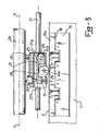
- the cutter device 15 for cutting across the sheet 3 and film 4 comprises two knife dies, both indicated at 18, which extend transversely along a perpendicular y-y direction to the x-x direction between the two side frames 7 and 8.
- the two dies 18 are attached rigidly to a die holder plate 19.
- the die holder plate 19 is guided movingly in the frame 5 between the side frames 7 and 8 of an up and down motion under the action of a drive means, known per se and not shown, such as a pair of air-operated cylinders, between a raised working position whereat the knife dies 18 are interposed to two arrays of dimples 2a, and an inoperative position whereat they are brought down and away.
- the cutter device 15 also comprises a carriage 20 which is movable back and forth, under the action of a drive means 20c, along and above the knife dies 18 in the y-y direction.
- the carriage 20 is supported on two guide bars 21 lying bridge-fashion across the path 9 and secured to opposing heads 22 and 23 which are bolted on the side frames 7 and 8, respectively.
- the drive means 20c for reciprocating the carriage 20 consists of an air-operated cylinder 24 whose heads are attached to the heads 22 and 23.
- the cylinder 24 is advantageously of the so-called rodless type.
- the stroke length of the carriage 20 between the stroke end positions, indicated in the drawing at 20a and 20b, is selected to barely exceed the length of the knife dies 18.
- the cylinder 20 is sized to provide an adequate low travel speed for the carriage, e.g. of approximately 4 meters per minute.
- each roller 25 is held in rolling engagement, by pressure contact at a preset level, with a respective knife die 18.
- each roller 25 is mounted for free rotation around a pin 26 lying along the axis a-a and being carried on a respective lever arm 27 on a middle portion 28 of the arm.
- Each lever arm 28 is pivoted, at one end 27a thereof, on a pin 29 mounted on the carriage and having an axis b-b which lies parallel to the axis x-x.
- each generatrix line of the roller 25 will be perpendicular to the cutting edge 18a of its respective die 18.
- a pressure means 30 such as an air-operated minicylinder, which is mounted on the carriage 20 and urges the lever arm 27 against the bias force of an elastic means 31 comprising a return spring, for example.
- the minicylinder 30 loads the lever arm 27 downwards, and accordingly, urges the roller 25 into pressure contact against a respective die 18.
- the pressure contact exerted by the roller on the die, at the intersect point P of a roller generatrix line with the die cutting edge, has a preset desired force which is adjustable within a range of low values, e.g. of 50 kg, by varying the delivery pressure of air to the air-operated minicylinder 30.
- the amount of said force can be advantageously read, e.g. by means of a pressure gauge placed in the air delivery line to the minicylinder and having a suitable scale graduated to display the force.
- the longitudinal cutter device 16 comprises an electrically operated chuck 32 bridging the gap between the side frames 7 and 8 and provided with rotary blades 33 which engage with respective stationary anvil blades 34 supported on the frame 5.
- the machine of this invention will deliver four trays at each forward step of the sheet 3.
- thermoforming device 10 which will form a set of four dimples, the product loading station, the heat sealing device 14, and the transverse cutter device 15.
- the feeder device 11 for the film 4 and the longitudinal cutter device 16 are operative.
- the carriage 20 is operated to reciprocate during the sheet 3 standstills. More specifically, the carriage 20 will complete forward and backward strokes which are both working strokes, from the position 20a to the position 20b, and vice versa, during consecutive standstills of the sheet 3.
- the roller 25 will roll along the cutting edge 18a of its respective die 18, thereby the intersect point P of a generatrix line of the roller with the cutting edge will run along the cutting edge to provide a desired cut across the entire length of the die. Since the contact between the roller and the die is substantially punctiform, a high pressure is easily produced at that point on the sheet to be severed, even if the forces applied to the roller may be comparatively small.
- the principal advantage of the machine according to the invention resides in the unusual effectiveness of the transverse cutting action applied to the sheet over the entire length of the die, in a thorough and reliable manner.
- a further advantage is that it is simple construction-wise and has a lightweight low-cost structure by virtue of the transverse cut bringing into play very small forces and relatively low operating rates.
- the carriage stroke is, in fact, completed during the standstill between stepwise forward movements at overlapping times with the dimple thermoforming and product loading processes, which enhances a clean cut through the sheet.
Landscapes
- Engineering & Computer Science (AREA)
- Mechanical Engineering (AREA)
- Blow-Moulding Or Thermoforming Of Plastics Or The Like (AREA)
Applications Claiming Priority (2)
| Application Number | Priority Date | Filing Date | Title |
|---|---|---|---|
| IT1929787 | 1987-02-09 | ||
| IT19297/87A IT1202485B (it) | 1987-02-09 | 1987-02-09 | Macchina termoformatrice per confezionare vaschette chiuse per prodotti in generale |
Publications (1)
| Publication Number | Publication Date |
|---|---|
| EP0280659A1 true EP0280659A1 (de) | 1988-08-31 |
Family
ID=11156515
Family Applications (1)
| Application Number | Title | Priority Date | Filing Date |
|---|---|---|---|
| EP88830038A Ceased EP0280659A1 (de) | 1987-02-09 | 1988-02-03 | Thermoformmaschine zur Herstellung gesiegelter Verpackungsplatten für Produkte im allgemeinen |
Country Status (2)
| Country | Link |
|---|---|
| EP (1) | EP0280659A1 (de) |
| IT (1) | IT1202485B (de) |
Cited By (8)
| Publication number | Priority date | Publication date | Assignee | Title |
|---|---|---|---|---|
| EP1026083A1 (de) * | 1999-02-03 | 2000-08-09 | Thies Eggers | Schneidvorrichtung zum Heraustrennen von Packungen aus einem Strang |
| EP1093894A3 (de) * | 1996-05-14 | 2002-03-06 | Esselte N.V. | Schneidvorrichtung |
| DE10359479A1 (de) * | 2003-12-17 | 2005-07-21 | Cfs Germany Gmbh | Längsschneider |
| EP1598276A1 (de) * | 2004-05-17 | 2005-11-23 | Multivac Sepp Haggenmüller GmbH & Co. KG | Verpackungsmaschine und Verfahren zum Schneiden von Packungen |
| EP2228316A1 (de) * | 2009-03-09 | 2010-09-15 | VARIOVAC PS SystemPack GmbH | Kunststofffolienverpackung mit Etikett und Verpackungsmaschine und Verfahren zur kontinuierlichen Herstellung solcher Kunststofffolienverpackungen |
| CN101365626B (zh) * | 2006-01-13 | 2011-08-03 | 利乐拉瓦尔集团及财务有限公司 | 用于分离以薄板形式一起供应且单独施加在可注入食品的各自包装上的开口装置的方法和组件 |
| EP2444340A1 (de) * | 2010-10-21 | 2012-04-25 | Multivac Sepp Haggenmüller GmbH & Co. KG | System und Verfahren zum Ergreifen und Anheben von Objekten |
| CN107054719A (zh) * | 2016-03-17 | 2017-08-18 | 高琳 | 板材贴膜割膜装置和方法 |
Families Citing this family (2)
| Publication number | Priority date | Publication date | Assignee | Title |
|---|---|---|---|---|
| CN110002055A (zh) * | 2019-05-05 | 2019-07-12 | 中山市美图实业有限公司 | 一种餐具包装机的分料机构 |
| CN111684935B (zh) * | 2020-06-12 | 2021-05-14 | 农业农村部南京农业机械化研究所 | 一种工业大麻处理机 |
Citations (1)
| Publication number | Priority date | Publication date | Assignee | Title |
|---|---|---|---|---|
| US3759122A (en) * | 1972-05-22 | 1973-09-18 | Filper Corp | Package separator and corner cutting die for individual portions, and method |
-
1987
- 1987-02-09 IT IT19297/87A patent/IT1202485B/it active
-
1988
- 1988-02-03 EP EP88830038A patent/EP0280659A1/de not_active Ceased
Patent Citations (1)
| Publication number | Priority date | Publication date | Assignee | Title |
|---|---|---|---|---|
| US3759122A (en) * | 1972-05-22 | 1973-09-18 | Filper Corp | Package separator and corner cutting die for individual portions, and method |
Non-Patent Citations (1)
| Title |
|---|
| PATENT ABSTRACTS OF JAPAN, vol. 8, no. 220 (M-330)[1657], 6th October 1984; & JP-A-59 103 719 (ANZAI KASEI KOGYO K.K.) 15-06-1984 * |
Cited By (9)
| Publication number | Priority date | Publication date | Assignee | Title |
|---|---|---|---|---|
| EP1093894A3 (de) * | 1996-05-14 | 2002-03-06 | Esselte N.V. | Schneidvorrichtung |
| EP1026083A1 (de) * | 1999-02-03 | 2000-08-09 | Thies Eggers | Schneidvorrichtung zum Heraustrennen von Packungen aus einem Strang |
| DE10359479A1 (de) * | 2003-12-17 | 2005-07-21 | Cfs Germany Gmbh | Längsschneider |
| EP1598276A1 (de) * | 2004-05-17 | 2005-11-23 | Multivac Sepp Haggenmüller GmbH & Co. KG | Verpackungsmaschine und Verfahren zum Schneiden von Packungen |
| US7896792B2 (en) | 2004-05-17 | 2011-03-01 | Multivac Sepp Haggenmuller Gmbh & Co. Kg | Packaging machine and method for cutting packages |
| CN101365626B (zh) * | 2006-01-13 | 2011-08-03 | 利乐拉瓦尔集团及财务有限公司 | 用于分离以薄板形式一起供应且单独施加在可注入食品的各自包装上的开口装置的方法和组件 |
| EP2228316A1 (de) * | 2009-03-09 | 2010-09-15 | VARIOVAC PS SystemPack GmbH | Kunststofffolienverpackung mit Etikett und Verpackungsmaschine und Verfahren zur kontinuierlichen Herstellung solcher Kunststofffolienverpackungen |
| EP2444340A1 (de) * | 2010-10-21 | 2012-04-25 | Multivac Sepp Haggenmüller GmbH & Co. KG | System und Verfahren zum Ergreifen und Anheben von Objekten |
| CN107054719A (zh) * | 2016-03-17 | 2017-08-18 | 高琳 | 板材贴膜割膜装置和方法 |
Also Published As
| Publication number | Publication date |
|---|---|
| IT8719297A0 (it) | 1987-02-09 |
| IT1202485B (it) | 1989-02-09 |
Similar Documents
| Publication | Publication Date | Title |
|---|---|---|
| US2131808A (en) | Sanitary napkin machine | |
| US4819406A (en) | Compact form-fill-seal machine for automatic production of sealed packages | |
| US3605641A (en) | Ravioli making machine | |
| EP0280659A1 (de) | Thermoformmaschine zur Herstellung gesiegelter Verpackungsplatten für Produkte im allgemeinen | |
| EP0405595B1 (de) | Vorrichtung für die kontinuierliche Herstellung von Netzbeuteln | |
| US3238691A (en) | Packaging material register control | |
| CN219707497U (zh) | 往复式多列四边封包装机 | |
| DE1461923C3 (de) | Vorrichtung zum registerhaltigen Versiegeln von zwei eine Ware einschließenden Folienbahnen | |
| JPS6128480B2 (de) | ||
| US5017125A (en) | Apparatus for feeding a label to a cavity of a molding device for thermoforming plastic containers | |
| US5535573A (en) | Apparatus (blank unit) for feeding blanks to an article which is to be wrapped | |
| US3733773A (en) | Apparatus including reciprocating web feeding means for a continuously feeding web | |
| WO2008046526A1 (de) | Verpackungsmaschine mit einer etilkettierungsvorrichtung | |
| US4415399A (en) | Handle applicator | |
| US3735654A (en) | Blanking machine vacuum system | |
| US3461760A (en) | Trimming apparatus | |
| US2813798A (en) | Method for placing paper sheets between slices in a stack | |
| EP0485208A1 (de) | Kompakte Vorrichtung zum Formen, Füllen und Siegeln von Verpackungen in einem automatischen Herstellungsverfahren mittels eines verbesserten Mechanismus zum Querschneiden | |
| US3238826A (en) | Endless belt conveyor for intermittently conveying sheet material | |
| EP0160116A1 (de) | Fertigung von aufgewickelten Gebäckstücken | |
| US3846959A (en) | Bulk-loading apparatus | |
| US3802307A (en) | Method and apparatus for forming envelope blanks from a web | |
| US4204380A (en) | Device for conveying, stacking, and packing aligned laminations of electrical machines | |
| US3330092A (en) | Packaging machines | |
| FI65929C (fi) | Maskin foer att framstaella med i vaeggar indrivbara faestflikar foersedda hoern- eller kantbeslag foer laodor emballage containers eller andra behaollare |
Legal Events
| Date | Code | Title | Description |
|---|---|---|---|
| PUAI | Public reference made under article 153(3) epc to a published international application that has entered the european phase |
Free format text: ORIGINAL CODE: 0009012 |
|
| AK | Designated contracting states |
Kind code of ref document: A1 Designated state(s): AT BE CH DE ES FR GB GR LI LU NL SE |
|
| 17P | Request for examination filed |
Effective date: 19890120 |
|
| 17Q | First examination report despatched |
Effective date: 19901005 |
|
| RAP1 | Party data changed (applicant data changed or rights of an application transferred) |
Owner name: IDEALTECNICA S.R.L. |
|
| STAA | Information on the status of an ep patent application or granted ep patent |
Free format text: STATUS: THE APPLICATION HAS BEEN REFUSED |
|
| 18R | Application refused |
Effective date: 19920220 |