EP0280668B1 - Unité d'impression - Google Patents
Unité d'impression Download PDFInfo
- Publication number
- EP0280668B1 EP0280668B1 EP88850051A EP88850051A EP0280668B1 EP 0280668 B1 EP0280668 B1 EP 0280668B1 EP 88850051 A EP88850051 A EP 88850051A EP 88850051 A EP88850051 A EP 88850051A EP 0280668 B1 EP0280668 B1 EP 0280668B1
- Authority
- EP
- European Patent Office
- Prior art keywords
- inking roller
- roller
- lever
- lever arms
- printing unit
- Prior art date
- Legal status (The legal status is an assumption and is not a legal conclusion. Google has not performed a legal analysis and makes no representation as to the accuracy of the status listed.)
- Expired - Lifetime
Links
- 238000006073 displacement reaction Methods 0.000 description 2
- 230000006978 adaptation Effects 0.000 description 1
- 230000008021 deposition Effects 0.000 description 1
- 238000000034 method Methods 0.000 description 1
- 125000006850 spacer group Chemical group 0.000 description 1
Images

Classifications
-
- B—PERFORMING OPERATIONS; TRANSPORTING
- B41—PRINTING; LINING MACHINES; TYPEWRITERS; STAMPS
- B41F—PRINTING MACHINES OR PRESSES
- B41F31/00—Inking arrangements or devices
- B41F31/30—Arrangements for tripping, lifting, adjusting, or removing inking rollers; Supports, bearings, or forks therefor
- B41F31/32—Lifting or adjusting devices
- B41F31/34—Cam, eccentric, wedge, or like devices
-
- B—PERFORMING OPERATIONS; TRANSPORTING
- B41—PRINTING; LINING MACHINES; TYPEWRITERS; STAMPS
- B41F—PRINTING MACHINES OR PRESSES
- B41F31/00—Inking arrangements or devices
- B41F31/02—Ducts, containers, supply or metering devices
- B41F31/04—Ducts, containers, supply or metering devices with duct-blades or like metering devices
-
- B—PERFORMING OPERATIONS; TRANSPORTING
- B41—PRINTING; LINING MACHINES; TYPEWRITERS; STAMPS
- B41F—PRINTING MACHINES OR PRESSES
- B41F31/00—Inking arrangements or devices
- B41F31/30—Arrangements for tripping, lifting, adjusting, or removing inking rollers; Supports, bearings, or forks therefor
- B41F31/304—Arrangements for inking roller bearings, forks or supports
- B41F31/305—Eccentric bearings
Definitions
- the present invention relates to a printing unit comprising a rotary impression cylinder and a likewise rotary inking roller included in an inking device and adjustably spaced from said impression cylinder by means of a first lever device which is pivotal and eccentrically mounted in relation to the axis of rotation of said inking roller, the printing unit further having an ink metering device movable into wipe-off engagement with the inking roller.
- a printing unit of this type is previously known from EP-A-0,132,246 which is hereby included by reference. Although the object of the invention disclosed in this EP document is completely different from that of the present invention, the printing unit per se is of the same basic design.
- the printing unit includes a back pressure cylinder, an impression cylinder and an inking roller, all of which are rotatable, parallel to and adjustably spaced from each other.
- a fountain roller dips into an ink container and, during its rotation, deposits ink on the inking roller.
- One object of the present invention therefore is to provide a printing unit in which the inking roller and the doctor blade are adjustable in a simple and accurate manner so as to overcome or at least substantially reduce the above-mentioned shortcomings.
- Another object is to provide a printing unit in which the inking roller and the doctor blade constantly maintain their relative positions when adjusting the spacing between them or relative to other rollers and cylinders included in the printing unit.
- a further object is to provide a printing unit which ensures even deposition of ink on the inking roller by means of the doctor blade.
- the ink metering device is a doctor blade movable into wipe-off engagement with the inking roller; in that the unit further comprises a second pivotal lever device concentrically mounted in relation to the axis of rotation of the inking roller and eccentrically mounted in relation to the pivot axis of the first lever device; and in that said doctor blade is supported by said second lever device, whereby the doctor blade and the inking roller will maintain their relative positions when adjusting the spacing between the inking roller and the impression cylinder.
- Preferred embodiments of the invention are stated in the accompanying subclaims.
- Fig. 1 shows the printing unit according to the invention from above with certain parts in section.
- Fig. 2 shows the printing unit from the side with certain parts removed.
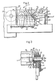
- Fig. 3 is a view taken along the line III-III in Fig. 1 with certain parts in section.
- a printing unit according to the invention generally designated 1 comprises rotary, parallel and adjustably spaced main components being a back pressure cylinder 2, an impression cylinder 3 and an inking roller 4 which are all mounted on a machine frame and more specifically in bearing brackets 5 and 6, respectively. It should be noted that the bearing bracket 6 is shown in section in a plane extending through said main components 2-4.
- an ink container 7 from which ink is drawn up by the roller 4 and applied to the impression cylinder 3 in a known manner.
- An elongate doctor blade 8 which is rotatable about its longitudinal axis is disposed behind and parallel to the inking roller 4. By being rotatable, the doctor blade 8 is biased so as to engage the inking roller 4 for wiping off ink drawn up from the ink container 7.
- Fig. 2 to which reference is now made, the printing unit 1 is shown from the side.
- parts of the bearing bracket 6 have been removed in the area of an inking device 9 comprising the roller 4, the container 7 and the doctor blade 8.
- the spacing of the inking roller 4 in relation to the impression cylinder 3 can be adjusted by means of two first, parallel and individually pivotal lever arms 10, 11 (only one of which is shown in Fig. 2), each mounted via an eccentric bushing 12 and 13, respectively (see Fig. 1), about the shaft 14 of the inking roller 4.
- the lever arms 10, 11 are pivoted about fulcrums 15 by operating adjusting devices 16 and 17, respectively, which are hingedly connected to the lever arms and, via components in the form of additional lever arms and adjusting devices (not shown in more detail), connected to the machine frame.
- the fulcrum 15 is spaced a distance e from the axis of rotation 18 of the inking roller 4, e thus representing the eccentricity of the lever arms 10, 11.
- Two second, parallel and individually pivotal lever arms 19 and 20 are mounted about the shaft 14 of the inking roller 4, as will be described in more detail further on.
- the doctor blade 8 is mounted between the second lever arms 19, 20 by means of holders 21, 22.
- adjusting devices 23, 24 hingedly connected to the free end portions of the second lever arms 19, 20 are mounted in the bearing brackets 5, 6.
- the hinge point 25 of the adjusting device 23 on the lever arm 19 is located on a level with the axis of rotation 18 of the inking roller 4.
- the hinge point 26 of the adjusting device 16 on the lever arm 10 is aligned with both the axis of rotation 18 and the fulcrum 15. This, taken together, means that pivotal movement of the lever arms 10, 11 and 19, 20 brings about negligible displacements in the vertical direction of the second lever arms 19, 20, between which the doctor blade 8 is disposed.
- the second lever arms 19, 20 are concentrically mounted in relation to the axis of rotation 18 of the inking roller 4 and eccentrically mounted in relation to the fulcrum 15 of the first lever arms 10, 11.
- the doctor blade 8 and the inking roller 4 maintain their relative positions thanks to this special arrangement of lever arms mounted concentrically and eccentrically in relation to the axis of rotation 18 of the inking roller 4.
- Fig. 3 shows in detail how the inking roller 4 is mounted in the bearing bracket 5.
- the eccentric bushing 13 comprises a substantially tubular portion 27 extending inwards towards the end of the inking roller 4 and forming a bearing on which the lever arm 20 is mounted.
- This figure also clearly shows the eccentricity e between the fulcrum or pivot axis 15 of the first lever arms 10, 11 and the fulcrum or pivot axis of the second lever arms 19, 20, the latter fulcrum or pivot axis coinciding with the axis or centre of rotation 18 of the inking roller 4.
- the eccentricity e should be considerably less than said spacing, preferably according to an approximate ratio of 1: 20, whereby the vertical displacement of the second lever arms 19, 20 becomes negligible.
- the second lever arms 19, 20 are mounted directly on the shaft 14 of the inking roller 4, the tubular portions 27 of the eccentric bushings 12, 13 preferably being replaced by bearings (not shown).
- the second lever arms 19, 20 and the bearing brackets 5, 6 are interconnected by means of a respective rod (not shown).
- These two rods which thus extend parallel to the roller and the cylinders of the printing unit, are preferably mounted at the locations where the ends of the adjusting devices 23, 24 are fixed to the bearing brackets 5, 6 and the second lever arms 19, 20, respectively (see Fig. 3).
- the two adjusting devices 23, 24 may, if so desired, be replaced by a single adjusting device (not shown) disposed midway between the bearing brackets 5, 6 and mounted between the above-mentioned rods (not shown).
- the present invention is also applicable to conventional printing units where the inking roller and the doctor blade are mounted directly on the bearing brackets.
- the bearing brackets 5, 6 may be designed otherwise, with or without gauge blocks 28 (see Fig. 1) serving as spacer means and intentionally not discussed in more detail in this specification.
- gauge blocks 28 see Fig. 1
- the web 29 on which a pressure should be exerted has not been described in more detail here either, since it can be fed into the printing unit at different locations and, possibly, by means of further rollers.
Landscapes
- Engineering & Computer Science (AREA)
- Mechanical Engineering (AREA)
- Inking, Control Or Cleaning Of Printing Machines (AREA)
- Coating Apparatus (AREA)
- Photoreceptors In Electrophotography (AREA)
- Developing Agents For Electrophotography (AREA)
- Electronic Switches (AREA)
- Non-Silver Salt Photosensitive Materials And Non-Silver Salt Photography (AREA)
Claims (7)
Priority Applications (1)
| Application Number | Priority Date | Filing Date | Title |
|---|---|---|---|
| AT88850051T ATE68411T1 (de) | 1987-02-13 | 1988-02-12 | Druckwerk. |
Applications Claiming Priority (2)
| Application Number | Priority Date | Filing Date | Title |
|---|---|---|---|
| SE8700575 | 1987-02-13 | ||
| SE8700575A SE453172B (sv) | 1987-02-13 | 1987-02-13 | Tryckverk |
Publications (2)
| Publication Number | Publication Date |
|---|---|
| EP0280668A1 EP0280668A1 (fr) | 1988-08-31 |
| EP0280668B1 true EP0280668B1 (fr) | 1991-10-16 |
Family
ID=20367507
Family Applications (1)
| Application Number | Title | Priority Date | Filing Date |
|---|---|---|---|
| EP88850051A Expired - Lifetime EP0280668B1 (fr) | 1987-02-13 | 1988-02-12 | Unité d'impression |
Country Status (7)
| Country | Link |
|---|---|
| US (1) | US5009159A (fr) |
| EP (1) | EP0280668B1 (fr) |
| AT (1) | ATE68411T1 (fr) |
| DE (1) | DE3865456D1 (fr) |
| ES (1) | ES2025332B3 (fr) |
| SE (1) | SE453172B (fr) |
| WO (1) | WO1988006097A1 (fr) |
Families Citing this family (8)
| Publication number | Priority date | Publication date | Assignee | Title |
|---|---|---|---|---|
| SE470283B (sv) * | 1992-05-22 | 1994-01-10 | Aake Boeoese | Kammarrakelanordning för tryckverk och tryckverk |
| DE19516224C2 (de) * | 1995-05-03 | 1997-03-20 | Windmoeller & Hoelscher | Rakelvorrichtung für ein Spülfarbwerk einer Rotationsdruckmaschine |
| US6276025B1 (en) | 1999-09-27 | 2001-08-21 | Xerox Corporation | Adjustable hinge |
| US6612238B2 (en) * | 2000-04-26 | 2003-09-02 | Heidelberger Druckmaschinen Ag | Inking unit in a printing machine |
| US6796228B2 (en) * | 2002-12-27 | 2004-09-28 | Day International, Inc. | Dampener metering device |
| US6886458B1 (en) * | 2003-12-18 | 2005-05-03 | Shinohara Machinery Co., Ltd. | Apparatus for adjusting printing pressure of satellite-type printing press |
| DE102005001193A1 (de) * | 2005-01-10 | 2006-07-20 | Steinemann Technology Ag | Zylinderdruckwerk |
| US20110132216A1 (en) * | 2009-12-09 | 2011-06-09 | 7242514 Canada Inc. | Stack angle compensation arrangement for a skewing adjustment system in an offset printing press |
Family Cites Families (3)
| Publication number | Priority date | Publication date | Assignee | Title |
|---|---|---|---|---|
| DE2746878C2 (de) * | 1977-10-19 | 1982-05-27 | Jan 26060 Kvindinge Stenqvist | Druckwerk |
| US4458590A (en) * | 1982-09-30 | 1984-07-10 | Harris Graphics Corporation | Printing press with plate cylinder skew and throw off |
| SE454664B (sv) * | 1983-07-18 | 1988-05-24 | Jan Stenqvist | Tryckverk |
-
1987
- 1987-02-13 SE SE8700575A patent/SE453172B/sv not_active IP Right Cessation
-
1988
- 1988-02-12 US US07/382,691 patent/US5009159A/en not_active Expired - Fee Related
- 1988-02-12 EP EP88850051A patent/EP0280668B1/fr not_active Expired - Lifetime
- 1988-02-12 ES ES88850051T patent/ES2025332B3/es not_active Expired - Lifetime
- 1988-02-12 WO PCT/SE1988/000052 patent/WO1988006097A1/fr not_active Ceased
- 1988-02-12 AT AT88850051T patent/ATE68411T1/de not_active IP Right Cessation
- 1988-02-12 DE DE8888850051T patent/DE3865456D1/de not_active Expired - Lifetime
Non-Patent Citations (1)
| Title |
|---|
| DEUTSCHER DRUCKER, Nr.10, 18.03.1982, R.A. Rehberg:"Flexotechnik im Zeitungsdruck", p.8+10 * |
Also Published As
| Publication number | Publication date |
|---|---|
| EP0280668A1 (fr) | 1988-08-31 |
| WO1988006097A1 (fr) | 1988-08-25 |
| ES2025332B3 (es) | 1992-03-16 |
| ATE68411T1 (de) | 1991-11-15 |
| US5009159A (en) | 1991-04-23 |
| DE3865456D1 (de) | 1991-11-21 |
| SE8700575D0 (sv) | 1987-02-13 |
| SE453172B (sv) | 1988-01-18 |
Similar Documents
| Publication | Publication Date | Title |
|---|---|---|
| US4475459A (en) | Impression cylinder for sheet-fed rotogravure presses | |
| EP0280668B1 (fr) | Unité d'impression | |
| US4365552A (en) | Automatic cylinder skewing apparatus | |
| GB2144677A (en) | Convertible printing unit with short inking device | |
| US3563173A (en) | Liquid-handling mechanism | |
| US5088407A (en) | Rotary printer for an envelope machine | |
| US5460088A (en) | Printing press | |
| US5230284A (en) | Mechanism for adjusting forme rollers at the plate cylinder of a rotary printing machine | |
| US4917012A (en) | Inking device for printing press and an inking dosing member construction | |
| US5272974A (en) | Offset printing apparatus with printing plate cylinder adjustment | |
| US4833988A (en) | Inking device for printing apparatus | |
| US5676057A (en) | Device for mounting a roller in a printing machine | |
| CA1066130A (fr) | Systeme de rouleaux essuyeurs | |
| EP0546029A1 (fr) | Machine d'imprimerie offset. | |
| US3163110A (en) | Interrupter for rotary printing machines | |
| US4429631A (en) | Auxiliary inking roller kit for duplicating press | |
| US3760723A (en) | Inking mechanism with adjustment for ductor roll oscillation | |
| CA1134672A (fr) | Reproducteur a pochoirs | |
| US5950539A (en) | Letterpress machine for continuous printing | |
| US5408928A (en) | Printing presses with inking units | |
| US4787312A (en) | Variable unit for supplying ink in an offset printing machine | |
| GB2032852A (en) | Inking apparatus | |
| EP0027321A1 (fr) | Machines à imprimer pour formats variables | |
| EP0337801A2 (fr) | Dispositif d'ajustement pour presse à imprimer rotative | |
| US20070079714A1 (en) | Upgrade kit for offset printers |
Legal Events
| Date | Code | Title | Description |
|---|---|---|---|
| PUAI | Public reference made under article 153(3) epc to a published international application that has entered the european phase |
Free format text: ORIGINAL CODE: 0009012 |
|
| AK | Designated contracting states |
Kind code of ref document: A1 Designated state(s): AT BE CH DE ES FR GB GR IT LI LU NL SE |
|
| 17P | Request for examination filed |
Effective date: 19890120 |
|
| 17Q | First examination report despatched |
Effective date: 19900618 |
|
| GRAA | (expected) grant |
Free format text: ORIGINAL CODE: 0009210 |
|
| AK | Designated contracting states |
Kind code of ref document: B1 Designated state(s): AT BE CH DE ES FR GB GR IT LI LU NL SE |
|
| PG25 | Lapsed in a contracting state [announced via postgrant information from national office to epo] |
Ref country code: SE Effective date: 19911016 Ref country code: NL Effective date: 19911016 Ref country code: LI Effective date: 19911016 Ref country code: GR Free format text: LAPSE BECAUSE OF FAILURE TO SUBMIT A TRANSLATION OF THE DESCRIPTION OR TO PAY THE FEE WITHIN THE PRESCRIBED TIME-LIMIT Effective date: 19911016 Ref country code: CH Effective date: 19911016 Ref country code: BE Effective date: 19911016 Ref country code: AT Effective date: 19911016 |
|
| REF | Corresponds to: |
Ref document number: 68411 Country of ref document: AT Date of ref document: 19911115 Kind code of ref document: T |
|
| ITF | It: translation for a ep patent filed | ||
| REF | Corresponds to: |
Ref document number: 3865456 Country of ref document: DE Date of ref document: 19911121 |
|
| ET | Fr: translation filed | ||
| REG | Reference to a national code |
Ref country code: CH Ref legal event code: PL |
|
| PG25 | Lapsed in a contracting state [announced via postgrant information from national office to epo] |
Ref country code: LU Free format text: LAPSE BECAUSE OF NON-PAYMENT OF DUE FEES Effective date: 19920229 |
|
| NLV1 | Nl: lapsed or annulled due to failure to fulfill the requirements of art. 29p and 29m of the patents act | ||
| REG | Reference to a national code |
Ref country code: ES Ref legal event code: FG2A Ref document number: 2025332 Country of ref document: ES Kind code of ref document: B3 |
|
| PLBE | No opposition filed within time limit |
Free format text: ORIGINAL CODE: 0009261 |
|
| STAA | Information on the status of an ep patent application or granted ep patent |
Free format text: STATUS: NO OPPOSITION FILED WITHIN TIME LIMIT |
|
| 26N | No opposition filed | ||
| PGFP | Annual fee paid to national office [announced via postgrant information from national office to epo] |
Ref country code: GB Payment date: 20000204 Year of fee payment: 13 Ref country code: DE Payment date: 20000204 Year of fee payment: 13 |
|
| PGFP | Annual fee paid to national office [announced via postgrant information from national office to epo] |
Ref country code: FR Payment date: 20000207 Year of fee payment: 13 |
|
| PGFP | Annual fee paid to national office [announced via postgrant information from national office to epo] |
Ref country code: ES Payment date: 20000217 Year of fee payment: 13 |
|
| PG25 | Lapsed in a contracting state [announced via postgrant information from national office to epo] |
Ref country code: GB Free format text: LAPSE BECAUSE OF NON-PAYMENT OF DUE FEES Effective date: 20010212 |
|
| PG25 | Lapsed in a contracting state [announced via postgrant information from national office to epo] |
Ref country code: ES Free format text: LAPSE BECAUSE OF NON-PAYMENT OF DUE FEES Effective date: 20010213 |
|
| GBPC | Gb: european patent ceased through non-payment of renewal fee |
Effective date: 20010212 |
|
| PG25 | Lapsed in a contracting state [announced via postgrant information from national office to epo] |
Ref country code: FR Free format text: LAPSE BECAUSE OF NON-PAYMENT OF DUE FEES Effective date: 20011031 |
|
| REG | Reference to a national code |
Ref country code: FR Ref legal event code: ST |
|
| PG25 | Lapsed in a contracting state [announced via postgrant information from national office to epo] |
Ref country code: DE Free format text: LAPSE BECAUSE OF NON-PAYMENT OF DUE FEES Effective date: 20011201 |
|
| REG | Reference to a national code |
Ref country code: ES Ref legal event code: FD2A Effective date: 20020916 |
|
| PG25 | Lapsed in a contracting state [announced via postgrant information from national office to epo] |
Ref country code: IT Free format text: LAPSE BECAUSE OF NON-PAYMENT OF DUE FEES;WARNING: LAPSES OF ITALIAN PATENTS WITH EFFECTIVE DATE BEFORE 2007 MAY HAVE OCCURRED AT ANY TIME BEFORE 2007. THE CORRECT EFFECTIVE DATE MAY BE DIFFERENT FROM THE ONE RECORDED. Effective date: 20050212 |