EP0280729B1 - Cadre en une piece pour tenir un element holographique dans un systeme holographique - Google Patents
Cadre en une piece pour tenir un element holographique dans un systeme holographique Download PDFInfo
- Publication number
- EP0280729B1 EP0280729B1 EP87907041A EP87907041A EP0280729B1 EP 0280729 B1 EP0280729 B1 EP 0280729B1 EP 87907041 A EP87907041 A EP 87907041A EP 87907041 A EP87907041 A EP 87907041A EP 0280729 B1 EP0280729 B1 EP 0280729B1
- Authority
- EP
- European Patent Office
- Prior art keywords
- holographic element
- frame
- border portion
- leg
- holographic
- Prior art date
- Legal status (The legal status is an assumption and is not a legal conclusion. Google has not performed a legal analysis and makes no representation as to the accuracy of the status listed.)
- Expired - Lifetime
Links
- 230000001154 acute effect Effects 0.000 claims 1
- 230000003287 optical effect Effects 0.000 description 9
- 239000000463 material Substances 0.000 description 4
- 238000000034 method Methods 0.000 description 4
- 239000011521 glass Substances 0.000 description 2
- 238000004519 manufacturing process Methods 0.000 description 2
- 238000012986 modification Methods 0.000 description 2
- 230000004048 modification Effects 0.000 description 2
- 239000000126 substance Substances 0.000 description 2
- 229920004142 LEXAN™ Polymers 0.000 description 1
- 239000004418 Lexan Substances 0.000 description 1
- CERQOIWHTDAKMF-UHFFFAOYSA-M Methacrylate Chemical compound CC(=C)C([O-])=O CERQOIWHTDAKMF-UHFFFAOYSA-M 0.000 description 1
- 239000007767 bonding agent Substances 0.000 description 1
- 238000010276 construction Methods 0.000 description 1
- 230000007423 decrease Effects 0.000 description 1
- 238000001746 injection moulding Methods 0.000 description 1
- 239000002184 metal Substances 0.000 description 1
- 238000006748 scratching Methods 0.000 description 1
- 230000002393 scratching effect Effects 0.000 description 1
Images
Classifications
-
- G—PHYSICS
- G03—PHOTOGRAPHY; CINEMATOGRAPHY; ANALOGOUS TECHNIQUES USING WAVES OTHER THAN OPTICAL WAVES; ELECTROGRAPHY; HOLOGRAPHY
- G03H—HOLOGRAPHIC PROCESSES OR APPARATUS
- G03H1/00—Holographic processes or apparatus using light, infrared or ultraviolet waves for obtaining holograms or for obtaining an image from them; Details peculiar thereto
- G03H1/02—Details of features involved during the holographic process; Replication of holograms without interference recording
- G03H2001/0208—Individual components other than the hologram
- G03H2001/0232—Mechanical components or mechanical aspects not otherwise provided for
Definitions
- This invention generally relates to frames for holographic elements, and more specifically to a frame particularly designed to facilitate locating holographic recording mediums, holographic lenses and matched filters precisely in position in systems such as holographic recording and correlator systems.
- DE-A-29 07 554 refers to an adjusting frame for holographic elements which comprises points of support and positioning pins on a frame portion formed by a surface.
- a handle frame With the aid of magnets, a handle frame is fixed in a self-centering manner in the adjusting frame.
- the handle frame may carry a holographic element
- Matched filters are made by exposing holographic recording mediums to certain types of diffraction patterns, and then developing the exposed recording mediums to produce holograms. These filters are used in optical correlator systems by directing certain light beams through the holograms on the matched filters and then processing the output therefrom to detect the presence or absence of a selected target in a scene or field of view.
- a filter having a large array of holograms it is possible to construct a filter having a large array of holograms, and, for example, a 50 mm x 50 mm matched filter may be made with a 100 x 100 array of holograms.
- Such a matched filter may be fabricated using a multiple beam generating holographic lens to generate an array of beams, and directing each of these beams toward a different area on a recording medium to produce an array of diffraction patterns thereon.
- Such a filter may be employed in an optical correlator system by using a similar or identical holographic lens to generate an array of beams, and directing each of these beams to a different hologram on the matched filter.
- the correlator system To operate the correlator system effectively, it is very important that the matched filter be located, with a very high degree of precision, in a specific position relative to the multiple beam generating holographic lense. Not only is the distance between these two elements critical, but their relative angular orientation and their relative lateral placement are also very important. For instance, the correlator system may be ineffective if the matched filter is laterally placed only 50 to 100 microns away from where it should be relative to the multiple beam generating lense.
- the correct relative position of the matched filter and the multiple beam generating lens in the correlator system depends on the position of the recording medium, from which the filter was made, relative to the multiple beam generating lens used to form the array of diffraction patterns on that recording medium. Because of this, in order to use the matched filter properly in the correlator system, it is also highly desirable that the recording medium, from which that filter was made, be located very accurately relative to the multiple beam lens used in the construction of the matched filter.
- Holographic systems are known that, with a relatively few adjustments in the components of the system, may be operated both to make a matched filter on a photographic plate, and also as an optical correlator using that filter, and where the correct position of the matched filter in the system, when it is used as a correlator, is identical to the position of the photographic plate from which that matched filter was made.
- Such systems substantially facilitate determining the correct position of the matched filter; however even with these systems, it is still very important to precisely position the photographic plate in the system, remove it, develop it, and then precisely position the developed matched filter back in the system.
- holographic recording mediums and matched filters usually include glass plate backings that often have rough outside edges, and these rough edges may cause the plates to tilt slightly if they are seated against edges of conventional frames or flat support surfaces. While this tilt may be very slight, it may produce a very undesirable deviation in the position of a holographic element. Also, sliding a rough edge of a glass plate against a flat or round pin support surface may cause the whole plate to chip along the edge or to crack.
- the present invention as defined in the claims includes a one piece frame for holding a holographic element in a holographic system, wherein the frame has a border portion, a seating portion, and a plurality of lateral positioning tabs.
- the border portion forms an outside border of the frame, and is flexible between an open position for receiving the holographic element, and a closed position for holding the holographic element in the frame.
- the seating portion is connected to and extends inward from the border portion to seat against a back surface of the holographic element.
- the lateral positioning tabs are connected to and extend inward from the border portion, above the seating portion, and are spaced apart from each other along the border portion to hold the holographic element therein spaced from said border portion.
- the border portion is biased toward the closed position to hold the holographic element against the lateral positioning tabs in a fixed position in, and with a preset angular orientation relative to, the frame, and to cooperate with the holographic element to maintain the frame in a fixed preset shape to facilitate placing and holding the holographic element in a precise location and orientation in the holographic system.
- the frame of this invention may have any suitable shape, with its shape preferably determined by the shape of the holographic optical element or elements with which the frame is intended for use.
- the frame may be made from any suitable material, although preferably the frame is made from a material that will withstand the chemicals used to process exposed holographic recording mediums.
- the frame of this invention may be reused with a number of different holographic elements; but, at the same time, with a preferred embodiment of the frame, a particular holographic element may be easily, permanently connected thereto.
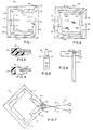
- Figures 1-4 illustrate holographic frame 10 in accordance with a preferred embodiment of the invention; and, generally, frame 10 comprises border portion 12, seating portion 14, and a plurality of lateral positioning tabs 16.
- border portion 12 includes legs 20, 22, 24 and 26; seating portion 14 includes a plurality of flat, coplanar surfaces 30, 32, 34 and 36; and lateral positioning tabs 16 includes reference tabs 40, 42 and 44 and pressure tabs 46 and 48.
- Border portion 12 forms the outside border or perimeter of frame 10, and is flexible between an open position, shown in Figure 1, and a closed position, shown in Figure 2.
- a holographic element 50 may be inserted into and removed from frame 10, and in the closed position, that element is securely held inside the frame.
- Border portion 12 is biased, for example by its inherent resiliency, toward the closed position to hold holographic element 50 against lateral positioning tabs 16 in a fixed position in, and with a preset angular orientation relative to, frame 10 --that is, a particular axis of element 50 is held in a particular preset angle relative to a particular axis of frame 10.
- border portion 12 cooperates with the holographic element to maintain the frame in a fixed preset shape to facilitate placing and holding the holographic element in a precise location and orientation in a holographic system.
- border portion 12 includes a split 52 to facilitate flexing the border portion between its open and closed positions.
- border portion 12 has a flat, square shape, with all four legs 20, 22, 24 and 26 having substantially the same length; and legs 20 and 22 are split apart to form the above-described split 52 in the border portion.
- Border portion 12 may, though, have shapes and sizes other than as shown in the drawing, and the preferred shape of the border portion generally matches the shape of the holographic plate, matched filter, or other holographic element with which frame 10 is used.
- the border portion may have a rectangular shape that is not also a square.
- the term holographic element includes holographic lenses, matched filters, other devices that actually contain a hologram, and also includes undeveloped photographic plates that may be used to record holograms.
- Seating portion 14 is connected to and extends inward from border portion 12 to seat against a back surface of holographic element 50.
- a back support surface extends inward from each leg of border portion 12.
- a first support surface 30 extends inward from leg 20
- a second support surface 32 extends inward from leg 22
- a third support surface 34 extends inward from leg 24, and a fourth support surface 36 extends inward from leg 26.
- Lateral positioning tabs 16 are connected to and extend inward from border portion 12, above seating portion 14, and are spaced apart from each other along that border portion to facilitate positioning and to hold holographic element 50 therein spaced from the border portion itself. More specifically, first and second reference tabs 40 and 42 extend inward from border portion 12 to engage a first side of holographic element 50, and third reference tab 44 extends inward from the border portion to engage a second side of the holographic element. First pressure tab 46 extends inward from border portion 12 to engage holographic element 50 opposite reference tabs 40 and 42 and to force the holographic element against those tabs, and second pressure tab 48 extends inward from the border portion to engage the holographic element opposite reference tab 44 and to force the holographic element against that tab. In order to balance the forces applied to holographic element 50 by the lateral positioning tabs, preferably pressure tab 46 is symmetrically positioned opposite reference tabs 40 and 42, and pressure tab 48 is directly opposite reference tab 44.
- border portion 12 includes four legs 20, 22, 24 and 26
- first and second reference tabs 40 and 42 extend inward from leg 24, equally spaced from the center of the longitudinal axis of that leg
- third reference tab 44 extends inward from leg 26, midway along its longitudinal axis.
- first pressure tab 46 extends inward from leg 20, midway between first and second reference tabs 40 and 42
- second pressure tab 48 extends inward from leg 22, directly opposite third reference tab 44.
- support surface 30 laterally projects directly inward of pressure tab 46
- support surface 32 laterally projects directly inward of pressure tab 48
- support surface 34 laterally projects directly inward of first and second reference tabs 40 and 42
- support surface 36 laterally projects directly inward of third reference tab 44.
- inside surfaces 40a, 42a, 44a, 46a and 48a of the reference and pressure tabs that directly engage optical element 50 are flat and smooth
- inside surfaces 40a and 42a of tabs 40 and 42 are also co-planar, and these latter surfaces are substantially parallel to inside surface 46a of tab 46 and substantially perpendicular to inside surfaces 44a and 48a of tabs 44 and 48.
- border portion 12 is moved to its open position, and the holographic element is placed inside that frame, with one edge of the holographic element against both first and second reference tabs 40 and 42. Then, holographic element 50 is slid along those two reference tabs 40 and 42 until the holographic element is brought against third reference tab 44. After this, border portion 12 is returned to its closed position, bringing pressure tabs 46 and 48 against holographic element 50. Pressure tab 46 forces holographic element 50 against reference tabs 40 and 42, and pressure tab 48 forces the holographic element against reference tab 44, securely holding the holographic element in place against those reference tabs.
- the bump may affect the position of holographic element 50 therein; and if any bump on the perimeter of the holographic element is rubbed across a surface of the frame, there is a chance that the holographic element may crack or chip.
- Tabs 40, 42, 44, 46 and 48 keep holographic element 50 spaced from the much larger inside, longitudinally extending surfaces of legs 20, 22, 24 and 26, and significantly decreases the chances that any bumps or projections on the edge of the holographic element will come into contact with any surfaces of frame 10 as the holographic element is placed and held in the frame.
- the use of two spaced apart and aligned reference tabs 40 and 42, as described above, substantially helps to initially position holographic element 50 in a particular orientation in frame 10, and to thereafter move the holographic element in a straight line along those tabs into its final position, against third reference tab 44, without any need to observe visually or to check the alignment or movement of the holographic element in the frame 10.
- border portion 12 of frame 10 includes a pair of openings 54 and 56, each one located on a different side of split 52, adapted to receive a tool to spread the border portion from its closed position to its open position.
- openings 54 and 56 may be located directly opposite each other, in opposite edges of legs 20 and 22, to form a common through opening in border portion 12.
- Figures 5 and 6 show a tool 60 that may be used with these openings to open border portion 12; and generally tool 60 includes front, frusto-conical portion 62, cylindrical portion 64 extending rearward therefrom, and handle portion 66 extending rearward from the cylindrical portion.
- frusto-conical portion 62 is small enough to fit into openings 54 and 56 when border portion 12 is in its closed position; and, in use, this end of tool 60 is pushed forward, through openings 54 and 56 so that the frusto-conical portion of the tool engages edges of those openings and pushes those edges away from each other, spreading border portion 12 from its closed position to its open position.
- tool 60 is pushed further forward so that cylindrical portion 64 is inserted into openings 54 and 56.
- the frictional contact between cylindrical portion 64 and the edges of openings 54 and 56 holds tool 60 in place within those openings, holding border portion 12 in its open position.
- Handle portion 66 is provided to help manipulate tool 60, and a forward portion of the handle radially projects outside cylindrical portion 64 and, in this way, forms a shoulder 68 to stop forward movement of tool 60 through openings 54 and 56.
- Figure 7 shows an alternate embodiment of border portion 12, where the openings, 54 and 56 are spaced apart. Specifically, opening 54 is located in leg 20, adjacent yet spaced from the edge of this leg that is opposite leg 22; and opening 56 is located in leg 22, adjacent yet spaced from the edge thereof that is opposite leg 20.
- Figure 7 also shows a scissor-type tool 70 that may be used with these openings 54 and 56 to move this border portion 12 into its open position; and, generally, tool 70 includes a pair of arms 72 and 74 pivotally connected together intermediate their ends, and a pair of pins 76 and 78 mounted on first ends of these arms and adapted to be inserted into openings 54 and 56.
- pins 76 and 78 are inserted into openings 54 and 56, and the front ends of arms 72 and 74 are pivoted apart to force and to hold openings 54 and 56 away from each other, to thereby force the border portion 12 into, and to hold it in, its open position.
- an optical element may be placed in or removed from frame 10. Then, the force applied to tool 70 to hold border portion 12 in its open position, is released, and the border portion flexes back into the closed position.
- frame 10 After a holographic element is secured in frame 10, the frame itself may be secured in a host holographic system in any suitable way. Border portion 12 of frame 10 may be securely and tightly gripped by appropriate holding equipment without that equipment scratching or otherwise damaging the optical element.
- at least one of the outside edges of frame 10 is flat and smooth so that the frame may be quickly and accurately positioned in a host holographic system by simply sliding the frame along a guide element or member thereof.
- frame 10 includes at least two outside edges, for example edges 24a and 26a, at a precise angular orientation relative to each other, and which thus may be used as reference edges to facilitate positioning frame 10 in a host system.
- Frame 10 may be used to position and hold a holographic recording medium in a holographic fabrication system, and after the desired exposure or exposures have been made on that medium, the frame-recording medium assembly is removed from the recording system, and processed with the appropriate developers, fixers and washes to produce, for example, either a holographic lense or a matched filter. When dry, the frame-filter or frame-lense assembly can then be mounted in an optical correlator system in the same way and with the same precision with which it was mounted in the fabrication system.
- Frame 10 may be reused with a number of different holographic elements; but, also, a particular holographic element may be permanently secured to a particular frame, if desired, by placing a suitable bonding agent in one or more of the recesses 80 formed between the frame and the holographic element.
- Frame 10 may be made in any suitable way, and preferably all the parts thereof are integrally connected together.
- frame 10 may be made via a stamping process or by means of an injection molding technique. If desired or necessary, the surfaces and edges of frame 10 may be machined to obtain the desired degree of smoothness, and outside edges of the frame may be metal clad or provided with studs to assist mounting the frame in a host holographic system.
- Frame 10 may be designed for any size or shape holographic element, and may be made from any suitable material.
- frame 10 is transparent and is made from a material, such as lexan, polymethyl, or methacrylate, that will withstand the chemicals used to process exposed recording mediums.
Landscapes
- Physics & Mathematics (AREA)
- General Physics & Mathematics (AREA)
- Holo Graphy (AREA)
- Diffracting Gratings Or Hologram Optical Elements (AREA)
Abstract
Claims (10)
- Cadre en une seule pièce pour tenir un élément holographique dans un système holographique, comprenant une partie bordure qui forme une bordure extérieure du cadre, des moyens d'appui et des moyens de positionnement latéral, caractérisé en ce qu'une fente de la partie bordure rend celle-ci capable de fléchir entre une position ouverte, pour recevoir l'élément holographique, et une position fermée, pour pouvoir tenir l'élément holographique dans le cadre, les moyens d'appui étant constitués par une partie d'appui reliée à la partie bordure et s'étendant vers l'intérieur à partir de celle-ci pour s'appuyer contre une face arrière de l'élément holographique ; et les moyens de positionnement latéral étant constitués par une pluralité de pattes de positionnement latéral qui sont solidaires de la partie bordure et s'étendent vers l'intérieur à partir de la partie bordure, au-dessus de la partie d'appui, les pattes de positionnement latéral étant espacées l'une de l'autre et le long de la partie bordure pour appliquer à l'élément holographique des forces de centrage pour forcer cet élément à prendre une position centrée dans le cadre, espacée de ladite partie bordure de ce cadre, et pour maintenir l'élément holographique dans cette position ; la partie bordure étant sollicitée vers la position fermée pour tenir l'élément holographique contre les pattes de positionnement latéral dans une position fixe dans le cadre et avec une orientation angulaire prédéterminée par rapport au cadre, et pour coopérer avec l'élément holographique en vue de maintenir le cadre dans une forme fixe prédéterminée pour faciliter le placement et le maintien de l'élément holographique dans une position et une orientation précises dans le système holographique.
- Cadre en une seule pièce selon la revendication 1, dans lequel la série de pattes de positionnement latéral comprend :
des première et seconde pattes de référence destinées à attaquer un premier côté de l'élément holographique ;
une troisième patte de référence destinée à attaquer un second côté de l'élément holographique ;
une première patte de pression destinée à attaquer l'élément holographique en face desdites première et seconde pattes de référence ; et
une seconde patte de pression destinée à attaquer l'élément holographique en face de la troisième patte de référence. - Cadre en une seule pièce selon les revendications 1 ou 2, caractérisé en ce que les pattes de positionnement latéral et la partie d'appui se rejoignent en formant un angle aigu pour permettre à la patte de positionnement de forcer l'élément holographique contre la partie d'appui.
- Cadre selon les revendications 2 ou 3, dans lequel la partie bordure possède une forme rectangulaire et comprend des première, seconde, troisième et quatrième branches et la partie d'appui comprend :(i) une première surface qui s'étend vers l'intérieur en partant de la première branche ;(ii) une seconde surface qui s'étend vers l'intérieur en partant de la seconde branche ;(iii) une troisième surface qui s'étend vers l'intérieur en partant de la troisième branche ; et(iv) une quatrième surface qui s'étend vers l'intérieur en partant de la quatrième branche.
- Cadre selon les revendications 3 ou 4, dans lequel:
chacune des première, seconde, troisième et quatrième branches possède un axe longitudinal ;
la première patte de pression s'étend vers l'intérieur en partant de la première branche, sensiblement au milieu de l'axe longitudinal de cette branche ;
la seconde patte de pression s'étend vers l'intérieur à partir de la seconde branche, sensiblement au milieu de l'axe longitudinal de celle-ci ;
les première et seconde pattes de référence s'étendent vers l'intérieur en partant de la troisième branche et sont espacées de la même distance du centre de l'axe longitudinal de la troisième branche ; et
la troisième patte de référence s'étend vers l'intérieur en partant de la quatrième branche, sensiblement au milieu de l'axe longitudinal de celle-ci. - Cadre selon la revendication 4, dans lequel les première et seconde branches sont espacées par une fente de façon à faciliter le déplacement de la partie bordure de la position fermée à la position ouverte.
- Cadre selon la revendication 6, dans lequel :
la première branche présente une première ouverture ;
la seconde branche présente une seconde ouverture ; et
les première et seconde ouvertures sont adaptées pour recevoir un outil servant à écarter les première et seconde branches l'une de l'autre et à faire passer la partie bordure de la position fermée à la position ouverte. - Cadre selon la revendication 7, dans lequel :
la première ouverture traverse un bord de la première branche qui est adjacent à la seconde branche ; et
la seconde ouverture s'étend à travers un bord de la seconde branche, en face de la première ouverture. - Cadre selon la revendication 6, qui comprend en outre un moyen servant à faire passer la partie bordure de la position fermée à une position ouverte.
- Cadre selon la revendication 1, dans lequel la partie bordure, la partie d'appui et les pattes de positionnement latéral sont toutes réunies en une seule pièce.
Applications Claiming Priority (2)
| Application Number | Priority Date | Filing Date | Title |
|---|---|---|---|
| US903275 | 1986-09-03 | ||
| US06/903,275 US4802718A (en) | 1986-09-03 | 1986-09-03 | One piece frame for holding a holographic element in a holographic system |
Publications (3)
| Publication Number | Publication Date |
|---|---|
| EP0280729A1 EP0280729A1 (fr) | 1988-09-07 |
| EP0280729A4 EP0280729A4 (fr) | 1989-01-26 |
| EP0280729B1 true EP0280729B1 (fr) | 1993-04-07 |
Family
ID=25417215
Family Applications (1)
| Application Number | Title | Priority Date | Filing Date |
|---|---|---|---|
| EP87907041A Expired - Lifetime EP0280729B1 (fr) | 1986-09-03 | 1987-08-31 | Cadre en une piece pour tenir un element holographique dans un systeme holographique |
Country Status (8)
| Country | Link |
|---|---|
| US (1) | US4802718A (fr) |
| EP (1) | EP0280729B1 (fr) |
| JP (1) | JPH0713777B2 (fr) |
| AU (1) | AU8151687A (fr) |
| CA (1) | CA1315575C (fr) |
| DE (1) | DE3785337T2 (fr) |
| IL (1) | IL83739A (fr) |
| WO (1) | WO1988001760A1 (fr) |
Families Citing this family (7)
| Publication number | Priority date | Publication date | Assignee | Title |
|---|---|---|---|---|
| US4929056A (en) * | 1988-09-08 | 1990-05-29 | Grumman Aerospace Corporation | Apparatus for opening and holding a frame and a method of mounting an optical element in a frame |
| US5170289A (en) * | 1991-02-01 | 1992-12-08 | Grumman Aerospace Corporation | Optical correlator console |
| US5172279A (en) * | 1992-03-05 | 1992-12-15 | Grumman Aerospace Corporation | Precision film input gate |
| US5488494A (en) * | 1993-10-07 | 1996-01-30 | Tamarack Storage Devices | Packaging system for holographic storage media |
| GB2376184A (en) * | 2001-06-08 | 2002-12-11 | Megaprint Group Ltd | Frame for an article |
| US20030067774A1 (en) * | 2001-10-04 | 2003-04-10 | Nanovia, L.P. | Illumination systems and methods employing diffractive holographic optical elements |
| US6972914B2 (en) * | 2004-03-17 | 2005-12-06 | Essilor International Compagnie Generale D'optique | Optical lens holder |
Family Cites Families (25)
| Publication number | Priority date | Publication date | Assignee | Title |
|---|---|---|---|---|
| US275316A (en) * | 1883-04-03 | Charles a | ||
| US587241A (en) * | 1897-07-27 | Picture-frame | ||
| US662736A (en) * | 1900-03-05 | 1900-11-27 | Louis B Prahar | Picture-frame. |
| US685695A (en) * | 1901-06-10 | 1901-10-29 | Jacob Lowenthal | Expansible frame. |
| US1291375A (en) * | 1917-04-28 | 1919-01-14 | Invisible Roll Screen Co Inc | Lantern-slide. |
| US1262528A (en) * | 1917-05-29 | 1918-04-09 | George H Lofland | Mounting for lenses. |
| US1775180A (en) * | 1927-06-16 | 1930-09-09 | Worsching Richard | Light screen for the lens of photographic cameras |
| US1987058A (en) * | 1934-04-10 | 1935-01-08 | Eastman Kodak Co | Filter holder |
| US2089236A (en) * | 1934-12-31 | 1937-08-10 | Welsh Mfg Co | Ophthalmic mounting |
| US2208642A (en) * | 1938-06-23 | 1940-07-23 | Testrite Instr Company Inc | Hand reading glass and the like |
| DE746397C (de) * | 1940-04-27 | 1944-08-10 | Georg Linser | Diapositivrahmen |
| US2268430A (en) * | 1940-12-04 | 1941-12-30 | Raoul P Silbernagel | Handle attaching means for mounting frames |
| US2388431A (en) * | 1944-02-26 | 1945-11-06 | Neiman Harry | Picture mount |
| US2823318A (en) * | 1954-12-16 | 1958-02-11 | X Ray Instr Corp | Expansible brace for film cassette |
| FR1163657A (fr) * | 1956-12-28 | 1958-09-30 | Cadre destiné à la projection de photographies dites diapositives | |
| US3678705A (en) * | 1970-05-21 | 1972-07-25 | Irving Korwin | Adjustable frame for ornament |
| US3871752A (en) * | 1973-08-20 | 1975-03-18 | Hygro Dynamics Ind Inc | Easily changeable filter holder |
| SU669368A1 (ru) * | 1978-02-21 | 1979-06-25 | Каунасский Политехнический Институт Им.Антанаса Снечкуса | Устройство дл фиксации пр моугольных информационных кассет |
| JPS5848641Y2 (ja) * | 1978-04-12 | 1983-11-07 | キヤノン株式会社 | レンズ保持装置 |
| FR2428163A1 (fr) * | 1978-06-06 | 1980-01-04 | Calmettes Marchou Et Cie | Organe de fixation du type collier de serrage |
| US4215890A (en) * | 1978-12-07 | 1980-08-05 | Milton Savage | Lens holder |
| DE2907555C2 (de) * | 1979-02-27 | 1981-04-30 | Philips Patentverwaltung Gmbh, 2000 Hamburg | Vorrichtung an einem holografischen Gerät mit einem justierbaren Justierrahmen |
| DE2907554C2 (de) * | 1979-02-27 | 1981-05-14 | Philips Patentverwaltung Gmbh, 2000 Hamburg | Vorrichtung an einem holografischen Gerät mit einem eine Hologrammplatte fassenden Hantierrahmen |
| JPS60115247A (ja) * | 1983-11-28 | 1985-06-21 | Fujitsu Ltd | 半導体装置 |
| DE3501425C1 (de) * | 1985-01-17 | 1986-07-24 | Geimuplast Peter Mundt Gmbh & Co Kg, 8105 Farchant | Einstueckiger Rahmen fuer Film-Diapositiv |
-
1986
- 1986-09-03 US US06/903,275 patent/US4802718A/en not_active Expired - Fee Related
-
1987
- 1987-08-31 JP JP62506380A patent/JPH0713777B2/ja not_active Expired - Lifetime
- 1987-08-31 WO PCT/US1987/002215 patent/WO1988001760A1/fr not_active Ceased
- 1987-08-31 DE DE87907041T patent/DE3785337T2/de not_active Expired - Lifetime
- 1987-08-31 AU AU81516/87A patent/AU8151687A/en not_active Abandoned
- 1987-08-31 EP EP87907041A patent/EP0280729B1/fr not_active Expired - Lifetime
- 1987-09-02 IL IL83739A patent/IL83739A/xx not_active IP Right Cessation
- 1987-09-02 CA CA000545922A patent/CA1315575C/fr not_active Expired - Fee Related
Also Published As
| Publication number | Publication date |
|---|---|
| AU8151687A (en) | 1988-03-24 |
| US4802718A (en) | 1989-02-07 |
| DE3785337T2 (de) | 1993-11-04 |
| EP0280729A1 (fr) | 1988-09-07 |
| CA1315575C (fr) | 1993-04-06 |
| WO1988001760A1 (fr) | 1988-03-10 |
| JPH01500861A (ja) | 1989-03-23 |
| DE3785337D1 (de) | 1993-05-13 |
| EP0280729A4 (fr) | 1989-01-26 |
| JPH0713777B2 (ja) | 1995-02-15 |
| IL83739A (en) | 1991-06-30 |
Similar Documents
| Publication | Publication Date | Title |
|---|---|---|
| US4012111A (en) | Microscope object slide positioning system | |
| KR100523824B1 (ko) | 기판홀더 및 디바이스 제조방법 | |
| EP0280729B1 (fr) | Cadre en une piece pour tenir un element holographique dans un systeme holographique | |
| US4452526A (en) | Step-and-repeat projection alignment and exposure system with auxiliary optical unit | |
| US4936655A (en) | Alignment fixture for an optical instrument | |
| EP0309947B1 (fr) | Méthode de production d'ouvertures sur un réseau de lentilles | |
| US4609264A (en) | Apparatus for positioning flat objects for microscopic examination | |
| EP0035113B1 (fr) | Dispositif d'alignement | |
| CA1310205C (fr) | Technique d'analyse quantitative pour lentilles | |
| US4597664A (en) | Step-and-repeat projection alignment and exposure system with auxiliary optical unit | |
| GB1305792A (fr) | ||
| TW200527149A (en) | Assembly of a reticle holder and a reticle | |
| US4993809A (en) | Mounting fixture for an optical instrument | |
| US4134651A (en) | Method of making an assembly | |
| US6185830B1 (en) | Semiconductor wafer fixture for alignment in a grating exposure process | |
| JPH04156505A (ja) | 光学系構成用のレンズ支持体へのレンズ接着固定方法 | |
| US4043653A (en) | Holographic high resolution contact printer | |
| EP0215070B1 (fr) | Plaque de support a contour transparent pour film | |
| USH616H (en) | Method of making a pre-aligned optical correlator | |
| KR0122312Y1 (ko) | 웨이퍼 노광장치 | |
| JPS6122626A (ja) | 投影露光装置 | |
| SU956980A1 (ru) | Способ контрол непараллельности оптических деталей | |
| EP0142959A1 (fr) | Procédé pour l'obtention d'une composition photographique comprenant deux images identiques disposées orthogonalement ainsi que dispositif pour l'exécution de ce procédé | |
| US6084236A (en) | System for mounting a hubless glassmaster onto an orders measurement device | |
| JPH0618349Y2 (ja) | 透明被写体用の保持シート |
Legal Events
| Date | Code | Title | Description |
|---|---|---|---|
| PUAI | Public reference made under article 153(3) epc to a published international application that has entered the european phase |
Free format text: ORIGINAL CODE: 0009012 |
|
| 17P | Request for examination filed |
Effective date: 19880503 |
|
| AK | Designated contracting states |
Kind code of ref document: A1 Designated state(s): DE FR GB IT |
|
| A4 | Supplementary search report drawn up and despatched |
Effective date: 19890126 |
|
| 17Q | First examination report despatched |
Effective date: 19910718 |
|
| GRAA | (expected) grant |
Free format text: ORIGINAL CODE: 0009210 |
|
| AK | Designated contracting states |
Kind code of ref document: B1 Designated state(s): DE FR GB IT |
|
| PG25 | Lapsed in a contracting state [announced via postgrant information from national office to epo] |
Ref country code: IT Free format text: LAPSE BECAUSE OF FAILURE TO SUBMIT A TRANSLATION OF THE DESCRIPTION OR TO PAY THE FEE WITHIN THE PRE;WARNING: LAPSES OF ITALIAN PATENTS WITH EFFECTIVE DATE BEFORE 2007 MAY HAVE OCCURRED AT ANY TIME BEFORE 2007. THE CORRECT EFFECTIVE DATE MAY BE DIFFERENT FROM THE ONE RECORDED.SCRIBED TIME-LIMIT Effective date: 19930407 |
|
| REF | Corresponds to: |
Ref document number: 3785337 Country of ref document: DE Date of ref document: 19930513 |
|
| ET | Fr: translation filed | ||
| PG25 | Lapsed in a contracting state [announced via postgrant information from national office to epo] |
Ref country code: GB Effective date: 19930831 |
|
| PLBE | No opposition filed within time limit |
Free format text: ORIGINAL CODE: 0009261 |
|
| STAA | Information on the status of an ep patent application or granted ep patent |
Free format text: STATUS: NO OPPOSITION FILED WITHIN TIME LIMIT |
|
| 26N | No opposition filed | ||
| GBPC | Gb: european patent ceased through non-payment of renewal fee |
Effective date: 19930831 |
|
| PG25 | Lapsed in a contracting state [announced via postgrant information from national office to epo] |
Ref country code: FR Effective date: 19940429 |
|
| PG25 | Lapsed in a contracting state [announced via postgrant information from national office to epo] |
Ref country code: DE Effective date: 19940503 |
|
| REG | Reference to a national code |
Ref country code: FR Ref legal event code: ST |