EP0280747A1 - Dispositif de fermeture - Google Patents
Dispositif de fermeture Download PDFInfo
- Publication number
- EP0280747A1 EP0280747A1 EP87102894A EP87102894A EP0280747A1 EP 0280747 A1 EP0280747 A1 EP 0280747A1 EP 87102894 A EP87102894 A EP 87102894A EP 87102894 A EP87102894 A EP 87102894A EP 0280747 A1 EP0280747 A1 EP 0280747A1
- Authority
- EP
- European Patent Office
- Prior art keywords
- locking
- key
- lock
- locking device
- parts
- Prior art date
- Legal status (The legal status is an assumption and is not a legal conclusion. Google has not performed a legal analysis and makes no representation as to the accuracy of the status listed.)
- Ceased
Links
- 230000000903 blocking effect Effects 0.000 claims abstract description 21
- 230000006835 compression Effects 0.000 claims description 9
- 238000007906 compression Methods 0.000 claims description 9
- 230000009471 action Effects 0.000 claims description 5
- 238000013459 approach Methods 0.000 claims description 5
- 230000003014 reinforcing effect Effects 0.000 claims description 5
- 230000008878 coupling Effects 0.000 claims description 4
- 238000010168 coupling process Methods 0.000 claims description 4
- 238000005859 coupling reaction Methods 0.000 claims description 4
- 239000000463 material Substances 0.000 claims description 3
- 239000012858 resilient material Substances 0.000 claims 1
- 238000006073 displacement reaction Methods 0.000 abstract description 6
- 230000008859 change Effects 0.000 description 7
- 238000000034 method Methods 0.000 description 2
- 230000008569 process Effects 0.000 description 2
- 238000005452 bending Methods 0.000 description 1
- 230000009286 beneficial effect Effects 0.000 description 1
- 230000008901 benefit Effects 0.000 description 1
- 238000011161 development Methods 0.000 description 1
- 230000018109 developmental process Effects 0.000 description 1
- 230000000694 effects Effects 0.000 description 1
- 230000008672 reprogramming Effects 0.000 description 1
Images


Classifications
-
- E—FIXED CONSTRUCTIONS
- E05—LOCKS; KEYS; WINDOW OR DOOR FITTINGS; SAFES
- E05B—LOCKS; ACCESSORIES THEREFOR; HANDCUFFS
- E05B27/00—Cylinder locks or other locks with tumbler pins or balls that are set by pushing the key in
- E05B27/02—Cylinder locks or other locks with tumbler pins or balls that are set by pushing the key in operated by the edge of the key
- E05B27/08—Cylinder locks or other locks with tumbler pins or balls that are set by pushing the key in operated by the edge of the key arranged axially
- E05B27/083—Cylinder locks or other locks with tumbler pins or balls that are set by pushing the key in operated by the edge of the key arranged axially of the split-pin tumbler type
-
- E—FIXED CONSTRUCTIONS
- E05—LOCKS; KEYS; WINDOW OR DOOR FITTINGS; SAFES
- E05B—LOCKS; ACCESSORIES THEREFOR; HANDCUFFS
- E05B19/00—Keys; Accessories therefor
- E05B19/18—Keys adjustable before use
-
- E—FIXED CONSTRUCTIONS
- E05—LOCKS; KEYS; WINDOW OR DOOR FITTINGS; SAFES
- E05B—LOCKS; ACCESSORIES THEREFOR; HANDCUFFS
- E05B35/00—Locks for use with special keys or a plurality of keys ; keys therefor
- E05B35/08—Locks for use with special keys or a plurality of keys ; keys therefor operable by a plurality of keys
Definitions
- the invention relates to a locking device consisting of a key and lock with a shaft arranged inside the lock and locked in the locked state, the shaft end of which is designed as a coupling for non-rotatably attaching the key provided for adjusting the key secret with length-adjustable plungers.
- Locking devices are known in which a key is used, the key shaft of which has various elevations and depressions or a correspondingly designed key bit, which acts on the tumblers, so that they can be brought into the release position to open the locking device. If the key is lost and no replacement key is available or can be produced, the lock is worthless and must be exchanged for another one.
- So-called permutation locks are also known, these are keyless locks, in which the key secret can be set as a sequence of numbers by turning disks, wheels, etc. If the key secret is known, the lock can be opened. If an unauthorized person has somehow found out the key secret, which a skilled person can do, for example, by listening to the number discs, this permutation lock is also worthless and can no longer serve its purpose. Apart from that, these locks are limited in their use and mostly unreliable due to the lack of security against unauthorized persons.
- the object of the invention is to provide a locking device consisting of a key and lock of the type mentioned, which can be used anywhere, so that the authorized person only needs a single key for all locks, it being ensured that an unauthorized person is not in the Is able to open the locking device.
- the authorized person should be able to change the key secret at any time without the use of tools.
- the authorized person should therefore be able to change the key secret quickly and partially or completely without difficulty.
- the locking device should be compact and versatile. It should not be possible for unauthorized persons to scan or intercept the key secret.
- the locking device thus has a shaft with cams in a central arrangement within the lock, which cooperate with diametrically opposite locking or locking elements. Blocking lugs are attached to the locking elements. Furthermore, locking units are provided which are in the correct, i.e. the key secret corresponding position when turning the lock shaft with a key coupled to a yielding or pivoting of the locking elements allow so that the lock shaft can be rotated into the release position.
- the locking elements themselves are designed to be resilient and automatically pivot back into the starting position when the lock shaft is turned back.
- the locking units are moved into the unlocking position by means of tappets on the key, each of which protrudes axially by a certain amount corresponding to the key secret (code) and, when the key is placed on the lock shaft, the locking units each by the amount of their effective length with which they come out protrude the key body, move inwards until a breakthrough of the locking units is in accordance with the displacement path of the blocking approaches of the locking elements.
- the blocking lugs enter these openings, which makes pivoting of the locking elements possible in the first place.
- the locks units formed in two parts, namely they each consist of a slidably displaceable guide part, which is under the action of a compression spring, and a locking part slidably arranged within the guide part, which carries the opening adapted to the respective blocking approach.
- the guide parts can now be axially displaced, ie the relative position of the Locking parts within the guide parts are changed, which means that there is a corresponding change in the key secret of the lock.
- the axial displacement of the guide parts is carried out when the key is attached by changing the key secret, ie when the effective lengths of the plunger of the key are set, this setting is transferred directly to the guide parts, that is to say the locking units of the lock. No special tools or devices are required, nor is it necessary to replace the locking units. Even inexperienced users can quickly change the code of the lock in this way by simply changing the code when the key is inserted. This new code of the key is thus "imprinted" on the code of the lock as soon as it is changed. However, such a re-setting of the key secret or code is only possible for those who know the current key secret. An unauthorized person cannot change the code.
- the invention is further characterized by a key lock that effectively prevents unauthorized persons from touching the set code.
- the lock shaft carries a further square cam, which interacts with the locking or locking elements associated with resilient locking devices.
- the front edge of these locking devices, on which a reinforcing part can also be arranged, is designed as a locking edge. With a slight rotation of the lock shaft, the square engages the latching devices and pivots them outward, so that the latching edge engages in latching teeth arranged on the underside of the locking units and in this way locks the locking units so that displacement is not possible .
- the locking device according to the invention has a compact structure and can be easily installed instead of conventional locking devices. It has a high level of security against unauthorized persons. The authorized person can change the lock code at any time and without difficulty, which further increases security. If there are four locking units in the lock, each of which can be adjusted by ten levels, there are ten thousand different setting options. With six locking units, the setting options increase to one million, so that the locking device can be adapted to the required level of security. Since the locking device can be used anywhere, be it in the car, on doors, lockers, safes, etc., there is the further advantage that all locks can be operated with just one key. Since the key secret of the lock is set directly on the key, any other key of the same type can be used if the key is lost. It is impossible for unauthorized persons to feel or listen to the key secret.
- the lock shown in Fig. 1 in longitudinal section consists of the actual lock body 1, which is substantially cylindrical and receives the lock shaft 2 in a central arrangement.
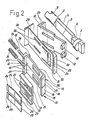
- the lock shaft 2, which, moreover, as well as other individual parts of the lock 3, can also be clearly seen in FIG. 2, has two diametrically opposed cams 4 and 5.
- a square 6 connects to these cams 4 and 5, while the following shaft end is designed as a coupling 7 for inserting the key 8, which is described in more detail in connection with FIGS. 3 and 4.
- At the other shaft end 9 is a not shown, acting on the actual, also not shown lock latch is arranged.
- the locking sets 12 rest against the locking units 13 and prevent them Because of the cams 4, 5 arranged on the lock shaft 2, the lock shaft 2 is rotated and thus the lock 3 is opened.
- the locking units 13 just mentioned are arranged in corresponding recesses in the lock body 1 and are under the action of the compression springs 14 which each locking unit 13 are assigned and are held and centered on the locking units 13 via an extension 15. The other end of the compression springs 14 is supported on the lock body 1.
- Each locking unit 13 consists of a guide part 16 and a locking part 17 which is arranged within the guide part 16 in a recess 18 of the same.
- the locking units 13 are displaceable in the axial direction within their cutouts, but are held by the compression spring 14 in the position shown in FIG. 1, in which the contact surfaces 19 are approximately flush with the end face 20 of the lock body 1.
- the locking parts 17 arranged within the guide parts 16 are in turn displaceable in their position relative to the respective guide part 16.
- Slot-like openings 21 are provided in the guide parts 16, into which the blocking projections 12 can enter.
- Openings 22 are arranged in the blocking parts 17, the dimensions of which correspond to the cross-sectional dimensions of the blocking projections 12 and are adapted to these.
- teeth 23 are also provided, so much that a total of ten tooth gaps are formed, in each of which a locking spring 24 can engage with its hook-like locking edge 25 and thus fixes the locking part 17 in its relative position to the guide part 16.
- the locking springs 24 are essentially designed as flat bending springs. You are within the ever because of the guide part 16 arranged above the associated locking part 17; its end 26 opposite the hook-like end 25 lies within an incision 27 in the guide part 16.
- the depressions 18 of the guide parts 16 are open to the sides, as can be clearly seen in particular in FIG. 2.
- the lateral guidance of the locking parts 17 located in the recesses 18 takes place on the one hand, i.e. the locking parts 17 make contact with their mutually facing side surfaces and, on the other hand, on the side surfaces of the cutouts in the lock body 1 receiving the guide parts 16.
- a variant of the guide part 16 is shown in FIG. 5.
- the recess 18 receiving the locking part 17 is delimited on all sides, because additional longitudinal walls 28 are provided, against which the locking part 17 with its side faces rests. As a result, improved guidance of the locking parts 17 within the guide parts 16 is achieved.
- two blocking units 13 are provided in pairs next to each other and diametrically opposite, i.e. a total of four locking units 13 are arranged within the lock body 1.
- further locking units 13 can be arranged, insofar as space permits.
- a locking device 29 is arranged between each locking or locking element 10, 11 and the associated locking units 13.
- the diametrically opposite locking devices 29 consist of tape material and are formed in one piece with one another, with the folds 30 forming support surfaces for the compression springs 14.
- the free end of the locking devices 29 is bent and designed as a locking edge or locking tooth 31.
- a reinforcing part 32 is arranged, which projects slightly beyond the locking edge 31, so that a second locking tooth 33 is formed.
- the latching devices 29 consist of tape material and are designed to be resilient at least in the area towards the latching edges 31.
- the locking teeth or locking edges 31, 33 cooperate with locking teeth 36 arranged on the underside of the guide parts 16.
- Slot-like recesses or openings 37, 38 are provided both on the locking or locking elements 10 and on the latching devices 29. In these openings 37, 38 extensions 39 engage on the underside of the guide parts 16, whereby the guidance is improved. At the same time, this limits the displacement of the locking units 13 in the axial direction.
- the reinforcing parts 32 rest on the square 6 of the lock shaft 2, so that the locking edges 31, 33 engage with a slight rotation of the lock shaft 2 between the locking teeth 36 of the locking units 13 and in this way prevent the locking units 13 or their guide parts 16 from shifting.
- the purpose of this device is explained in more detail below.
- the key 8 shown in FIGS. 3 and 4 is used to actuate the lock 3.
- This key 8 has plungers 37 which are adjustable in length.
- the plungers 37 rest against an eccentric or a spiral surface 38, which rotatably with the respective setting wheel 39, which from the outside Is rotatable and adjustable, are connected.
- a detent spring 40 which is assigned to each setting wheel 39, falls into a notch on the circumference of the setting wheel 39 during each setting step and holds the set wheel 39 in this position. In addition, this makes it possible to adjust the setting wheels or disks 39 even in the dark due to the ratchet noises, without the numbers on the setting wheel being recognizable.
- the counter-clutch 42 attached to the handle 41 of the key 8 in a manner fixed against relative rotation corresponds to the clutch 7 of the lock shaft 2.
- Each locking unit 13 is assigned a plunger 37.
- the openings 22 of the locking parts 17 get into the displacement path for the locking lugs 12 of the locking elements 10 which, when the lock shaft 2 is twisted outwards or can yield or pivot, and allow the lock shaft 2 to be twisted from the locked to the unlocked position.
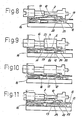
- FIGS. 6 to 11 show only one half of the lock in a schematic representation, namely in different stages of the closing process.
- Fig. 6 corresponds essentially to that 1 shown state of the lock, which is in the locked or closed position.
- the locking spring 24 is locked with the teeth 23 of the locking part 17; the locking part 17 is blocked within the guide part 16 and fixed in its position relative to the guide part 16.
- Fig. 7 the lock shaft 2 is rotated by a small amount, the locking unit 13 remaining in place, that is not shifted.
- the square 6 of the shaft 2 presses the latching device 29 with the latching edges 31, 33 into the tooth spaces of the latching teeth 36 of the guide part 16 via the reinforcing part 32.
- the guide part 16 and thus the locking unit 13 are not pushed in more is possible; effectively prevents scanning or eavesdropping on the key secret of the lock.
- the lock is shown in a position with a force-coupled key (not shown) with properly adjusted plungers according to the key secret or code.
- the corresponding locking unit 13 is brought into the unlocking position, in which the opening 22 of the locking part 17 comes exactly into the path of movement of the respective blocking projection 12.
- the lock shaft 2 can now be turned using the key 8 until the cams 4, 5 have pivoted the locking or locking elements 10 and 11 completely outwards and the locking lugs 12 have entered the openings 22 in the locking parts 17.
- the locking spring 24 is lifted out of the latching position by the blocking projection 12, so that the blocking of the locking part 17 within the guide part 16 is released.
- the lock was thus reprogrammed by simply turning the dials on the key to a new key secret, which can be done even by inexperienced users without any tools if they only know the current code setting of the lock. Such reprogramming of the lock is possible at any time and is always recommended if the code setting has become known to unauthorized persons due to indiscretion.
- an encryption table can be arranged on the handle of the key, which enables the authorized person to memorize the respective key secret, which is represented as a sequence of digits, as a word, which is of course much easier.
Landscapes
- Lock And Its Accessories (AREA)
Priority Applications (1)
| Application Number | Priority Date | Filing Date | Title |
|---|---|---|---|
| EP87102894A EP0280747A1 (fr) | 1987-02-28 | 1987-02-28 | Dispositif de fermeture |
Applications Claiming Priority (1)
| Application Number | Priority Date | Filing Date | Title |
|---|---|---|---|
| EP87102894A EP0280747A1 (fr) | 1987-02-28 | 1987-02-28 | Dispositif de fermeture |
Publications (1)
| Publication Number | Publication Date |
|---|---|
| EP0280747A1 true EP0280747A1 (fr) | 1988-09-07 |
Family
ID=8196790
Family Applications (1)
| Application Number | Title | Priority Date | Filing Date |
|---|---|---|---|
| EP87102894A Ceased EP0280747A1 (fr) | 1987-02-28 | 1987-02-28 | Dispositif de fermeture |
Country Status (1)
| Country | Link |
|---|---|
| EP (1) | EP0280747A1 (fr) |
Cited By (2)
| Publication number | Priority date | Publication date | Assignee | Title |
|---|---|---|---|---|
| WO1995034731A1 (fr) * | 1994-06-10 | 1995-12-21 | Ymos Aktiengesellschaft | Systeme de fermeture, notamment pour automobiles et equipements de batiments |
| CN112282515A (zh) * | 2020-11-11 | 2021-01-29 | 中山市基信锁芯有限公司 | 一种管理锁芯 |
Citations (3)
| Publication number | Priority date | Publication date | Assignee | Title |
|---|---|---|---|---|
| DE2418589A1 (de) * | 1973-04-23 | 1974-11-14 | Jonathan Lock Ltd | Einstellbarer schluessel fuer zylinderschloesser |
| US4112820A (en) * | 1977-11-23 | 1978-09-12 | Nordica International, Inc. | Tamper-proof axial tumbler type lock |
| EP0212651A2 (fr) * | 1985-08-27 | 1987-03-04 | Alfred Sperber | Serrure |
-
1987
- 1987-02-28 EP EP87102894A patent/EP0280747A1/fr not_active Ceased
Patent Citations (3)
| Publication number | Priority date | Publication date | Assignee | Title |
|---|---|---|---|---|
| DE2418589A1 (de) * | 1973-04-23 | 1974-11-14 | Jonathan Lock Ltd | Einstellbarer schluessel fuer zylinderschloesser |
| US4112820A (en) * | 1977-11-23 | 1978-09-12 | Nordica International, Inc. | Tamper-proof axial tumbler type lock |
| EP0212651A2 (fr) * | 1985-08-27 | 1987-03-04 | Alfred Sperber | Serrure |
Cited By (3)
| Publication number | Priority date | Publication date | Assignee | Title |
|---|---|---|---|---|
| WO1995034731A1 (fr) * | 1994-06-10 | 1995-12-21 | Ymos Aktiengesellschaft | Systeme de fermeture, notamment pour automobiles et equipements de batiments |
| US5791181A (en) * | 1994-06-10 | 1998-08-11 | Valeo Gmbh & Co. Schliessysteme Kg | Locking system, particularly for motor vehicles and building fixtures |
| CN112282515A (zh) * | 2020-11-11 | 2021-01-29 | 中山市基信锁芯有限公司 | 一种管理锁芯 |
Similar Documents
| Publication | Publication Date | Title |
|---|---|---|
| DE60303099T2 (de) | Umstellbares Zylinderschloss mit seitlichem Riegel | |
| EP0621384A1 (fr) | Clé et cylindre pour une serrure de sécurité | |
| DE102011015314A1 (de) | Schließzylinder | |
| DE2823022C2 (de) | Permutationsschloß | |
| DE2103476A1 (de) | Schloßmechanismus | |
| DE3641148C2 (fr) | ||
| EP1267022B1 (fr) | Dispositif de verrouillage d'urgence | |
| DE19544840A1 (de) | Zylinderschloß mit Zylinderkern und Zuhaltungen | |
| DE3040586C2 (de) | Aufsetzschloß mit einer Schubfalle | |
| EP0349738B1 (fr) | Cylindre de fermeture | |
| DE3526173A1 (de) | Schluessel fuer zwei in unterschiedlichen drehrichtungen entsperrbare schliesszylinder | |
| DE2644367C3 (de) | Magnetschlüsselbetätigter Schließzylinder | |
| EP0212651A2 (fr) | Serrure | |
| DE2224412C3 (de) | Kombinationsschloß | |
| EP1156179A2 (fr) | Serrure cylindrique | |
| DE20318451U1 (de) | Zylinder für ein Sicherheitsschloß | |
| DE2646739A1 (de) | Schlossanordnung | |
| DE1653985B2 (de) | Permutationsschloss fuer wertbehaelter | |
| DE9218855U1 (de) | Codierbares Zylinderschloß | |
| DE2603846B2 (de) | Zugangs-Abdeckvorrichtung in einem Permutationsschloß | |
| EP0447354B1 (fr) | Serrure à gorges en forme de segment | |
| DE1249726B (fr) | ||
| DE3216481A1 (de) | Schluesselbetaetigter schliesszylinder | |
| DE1201718B (de) | Schloss mit Steckschluessel | |
| DE692315C (de) | Malschloss mit tastenartigen Einstellgliedern |
Legal Events
| Date | Code | Title | Description |
|---|---|---|---|
| PUAI | Public reference made under article 153(3) epc to a published international application that has entered the european phase |
Free format text: ORIGINAL CODE: 0009012 |
|
| AK | Designated contracting states |
Kind code of ref document: A1 Designated state(s): AT BE CH DE ES FR GB GR IT LI LU NL SE |
|
| 17P | Request for examination filed |
Effective date: 19890220 |
|
| 17Q | First examination report despatched |
Effective date: 19900208 |
|
| STAA | Information on the status of an ep patent application or granted ep patent |
Free format text: STATUS: THE APPLICATION HAS BEEN REFUSED |
|
| 18R | Application refused |
Effective date: 19900807 |