EP0280762A2 - Procédé et appareil pour la production de biogaz à partir de milieux épais fermentescibles - Google Patents
Procédé et appareil pour la production de biogaz à partir de milieux épais fermentescibles Download PDFInfo
- Publication number
- EP0280762A2 EP0280762A2 EP87112084A EP87112084A EP0280762A2 EP 0280762 A2 EP0280762 A2 EP 0280762A2 EP 87112084 A EP87112084 A EP 87112084A EP 87112084 A EP87112084 A EP 87112084A EP 0280762 A2 EP0280762 A2 EP 0280762A2
- Authority
- EP
- European Patent Office
- Prior art keywords
- fermentation
- mixing
- container
- mixing body
- plant according
- Prior art date
- Legal status (The legal status is an assumption and is not a legal conclusion. Google has not performed a legal analysis and makes no representation as to the accuracy of the status listed.)
- Granted
Links
Images


Classifications
-
- C—CHEMISTRY; METALLURGY
- C12—BIOCHEMISTRY; BEER; SPIRITS; WINE; VINEGAR; MICROBIOLOGY; ENZYMOLOGY; MUTATION OR GENETIC ENGINEERING
- C12M—APPARATUS FOR ENZYMOLOGY OR MICROBIOLOGY; APPARATUS FOR CULTURING MICROORGANISMS FOR PRODUCING BIOMASS, FOR GROWING CELLS OR FOR OBTAINING FERMENTATION OR METABOLIC PRODUCTS, i.e. BIOREACTORS OR FERMENTERS
- C12M27/00—Means for mixing, agitating or circulating fluids in the vessel
- C12M27/02—Stirrer or mobile mixing elements
- C12M27/04—Stirrer or mobile mixing elements with introduction of gas through the stirrer or mixing element
-
- C—CHEMISTRY; METALLURGY
- C12—BIOCHEMISTRY; BEER; SPIRITS; WINE; VINEGAR; MICROBIOLOGY; ENZYMOLOGY; MUTATION OR GENETIC ENGINEERING
- C12M—APPARATUS FOR ENZYMOLOGY OR MICROBIOLOGY; APPARATUS FOR CULTURING MICROORGANISMS FOR PRODUCING BIOMASS, FOR GROWING CELLS OR FOR OBTAINING FERMENTATION OR METABOLIC PRODUCTS, i.e. BIOREACTORS OR FERMENTERS
- C12M21/00—Bioreactors or fermenters specially adapted for specific uses
- C12M21/04—Bioreactors or fermenters specially adapted for specific uses for producing gas, e.g. biogas
-
- C—CHEMISTRY; METALLURGY
- C12—BIOCHEMISTRY; BEER; SPIRITS; WINE; VINEGAR; MICROBIOLOGY; ENZYMOLOGY; MUTATION OR GENETIC ENGINEERING
- C12M—APPARATUS FOR ENZYMOLOGY OR MICROBIOLOGY; APPARATUS FOR CULTURING MICROORGANISMS FOR PRODUCING BIOMASS, FOR GROWING CELLS OR FOR OBTAINING FERMENTATION OR METABOLIC PRODUCTS, i.e. BIOREACTORS OR FERMENTERS
- C12M23/00—Constructional details, e.g. recesses, hinges
- C12M23/34—Internal compartments or partitions
-
- C—CHEMISTRY; METALLURGY
- C12—BIOCHEMISTRY; BEER; SPIRITS; WINE; VINEGAR; MICROBIOLOGY; ENZYMOLOGY; MUTATION OR GENETIC ENGINEERING
- C12M—APPARATUS FOR ENZYMOLOGY OR MICROBIOLOGY; APPARATUS FOR CULTURING MICROORGANISMS FOR PRODUCING BIOMASS, FOR GROWING CELLS OR FOR OBTAINING FERMENTATION OR METABOLIC PRODUCTS, i.e. BIOREACTORS OR FERMENTERS
- C12M27/00—Means for mixing, agitating or circulating fluids in the vessel
- C12M27/02—Stirrer or mobile mixing elements
-
- C—CHEMISTRY; METALLURGY
- C12—BIOCHEMISTRY; BEER; SPIRITS; WINE; VINEGAR; MICROBIOLOGY; ENZYMOLOGY; MUTATION OR GENETIC ENGINEERING
- C12M—APPARATUS FOR ENZYMOLOGY OR MICROBIOLOGY; APPARATUS FOR CULTURING MICROORGANISMS FOR PRODUCING BIOMASS, FOR GROWING CELLS OR FOR OBTAINING FERMENTATION OR METABOLIC PRODUCTS, i.e. BIOREACTORS OR FERMENTERS
- C12M41/00—Means for regulation, monitoring, measurement or control, e.g. flow regulation
- C12M41/12—Means for regulation, monitoring, measurement or control, e.g. flow regulation of temperature
- C12M41/18—Heat exchange systems, e.g. heat jackets or outer envelopes
- C12M41/24—Heat exchange systems, e.g. heat jackets or outer envelopes inside the vessel
-
- Y—GENERAL TAGGING OF NEW TECHNOLOGICAL DEVELOPMENTS; GENERAL TAGGING OF CROSS-SECTIONAL TECHNOLOGIES SPANNING OVER SEVERAL SECTIONS OF THE IPC; TECHNICAL SUBJECTS COVERED BY FORMER USPC CROSS-REFERENCE ART COLLECTIONS [XRACs] AND DIGESTS
- Y02—TECHNOLOGIES OR APPLICATIONS FOR MITIGATION OR ADAPTATION AGAINST CLIMATE CHANGE
- Y02E—REDUCTION OF GREENHOUSE GAS [GHG] EMISSIONS, RELATED TO ENERGY GENERATION, TRANSMISSION OR DISTRIBUTION
- Y02E50/00—Technologies for the production of fuel of non-fossil origin
- Y02E50/30—Fuel from waste, e.g. synthetic alcohol or diesel
Definitions
- the present invention relates to a process for the production of biogas by fermentation of viscous media, in which the fermentation takes place in a fermentation tank in two stages, namely a first acid fermentation stage in which oxygen is consumed with the help of acid bacteria and a subsequent second fermentation stage in which the For example, biogas is generated with methane bacteria.
- the invention further relates to a plant for producing biogas by fermenting viscous media, in which fermentation is carried out in a preferably cylindrical container.
- the fermentation medium first enters a first fermentation chamber, in which the pre-fermentation is carried out with the help of acid bacteria, the so-called acid fermentation, in which, among other things, the oxygen present in the fermentation medium is consumed, since the methane bacteria used in the main fermentation find better living conditions when oxygen is excluded.
- acid fermentation in which, among other things, the oxygen present in the fermentation medium is consumed, since the methane bacteria used in the main fermentation find better living conditions when oxygen is excluded.
- the high molecular weight proteins, carbohydrates and fats present in the fermentation medium are also broken down into low molecular weight substances, especially fatty acids.
- As a metabolic product of the acid bacteria essentially CO2, H2 and H2S arise during acid fermentation.
- the fermentation medium then passes from the acid fermentation chamber into the actual main fermentation chamber, in which the methane bacteria generate the biogas from the first stage degradation products.
- a device for the mixing of the fermentation medium is provided, this is carried out in both fermentation chambers by conventional stirrers, for example when using cylindrical fermentation tanks with stirrers, the axis of rotation of which is the vertical tank axis, parts of the stirrer projecting radially outwards from this axis .
- the stirrer is rotated, the fermentation medium is set into a rotational movement around the central axis of the container. Since the fermentation medium also contains solids, the effect of the stirrer and the degree of mixing from the container axis to the outside decrease.
- the bacteria used in fermentation are sensitive to strong currents in the fermentation medium.
- the object of the present invention is therefore to improve a method of the type mentioned in such a way that the fermentation medium is mixed as slowly as possible continuously and continuously in all areas of the container without the bacteria-irritating strong currents or turbulence occurring in the fermentation medium, so that the biogas yield is maximized and the time spent in the tank is minimized.
- the solution to this problem is provided by a method in which the mixing takes place in both fermentation stages by slow, continuous movement of approximately plate-shaped mixing bodies in the container in the axial direction. If the container is standing, the mixing bodies, which extend almost over the entire cross section of the container, are moved up and down in the container. It is also conceivable to design the container horizontally, so that in this case the plate-shaped mixing bodies standing in the container, essentially covering the container cross-section, are moved along the container axis.
- the fermentation medium is either introduced warm into the container or heated in the container by underfloor or wall heating or also by heat exchangers. When heating the bottom or the wall of the container, part of the heat is lost through the container wall. In addition, heat escapes with the biogas flowing out. It is therefore provided according to the invention that the fermentation medium is heated up exclusively or at least additionally by heating the mixing bodies. Since the mixing bodies move continuously up and down in the fermentation medium, it is also heated uniformly everywhere. Since the mixing bodies are immersed in the fermentation medium, the heat losses are over Container bottom and wall low.
- the mixing bodies themselves are heated, for example by passing hot water through them, it is sufficient if the water has only a slightly higher flow temperature than the fermentation medium.
- a much higher flow temperature was required, which is thermally unfavorable.
- the fermentation medium is preheated by means of a heat exchanger before being fed into the acid fermentation chamber, preheating to approximately 20 ° -25 ° C. being appropriate.
- the first fermentation stage is aerobic or anaerobic with the aid of the acid bacteria.
- the subsequent methane fermentation must take place in the absence of oxygen.
- the acid fermentation chamber In the case of aerobic acid fermentation, the acid fermentation chamber must therefore be separated from the methane fermentation chamber.
- the invention provides for the excess heat to be dissipated via the mixing bodies, e.g. by passing cold water through the mixing body and thus cooling the fermentation medium.
- the mixing bodies reach the fermentation medium anywhere in the container, since the bacteria are sensitive to overheating.
- All viscous media can be fermented by the process according to the invention, in particular the process is well suited for the fermentation of liquid manure or sewage sludge.
- a continuous supply of the liquid manure for example over a period of 24 hours, makes sense.
- a pneumatic conveying device for example a special pump operated with compressed air
- the compressed air generated by a compressor has the advantage as a pump medium that it can be dosed very precisely.
- this pump contains no moving parts by which the liquid manure is agitated, so that turbulence which is harmful to the bacteria is avoided.
- the pump is the subject of a separate application by the applicant. In order to prevent acidification of the fermentation medium, the pH of the fermentation medium is measured when leaving the acid fermentation stage.
- the invention further relates to a plant for producing biogas by fermenting viscous media with a preferably cylindrical container in which the fermentation medium is fermented.
- the fermentation medium is mixed through plate-shaped mixing bodies, which can be concrete slabs, for example, and which are moved in the container in the axial direction.
- the mixing bodies can be suspended in the tank and raised or lowered in the vertical direction.
- the mixing bodies can be lifted, for example, by winding the suspension ropes onto a roller which is mounted at the top of the container and can be rotated about its horizontal axis.
- the fermentation tank can consist, for example, of an inner ring-shaped acid fermentation chamber which has a gas ventilation pipe through which the resulting unusable gases, mainly CO2, H2 and H2S can escape.
- the upstream acid fermentation is particularly advantageous when processing cattle manure, since its pH is quite right high.
- the acid bacteria develop acid, the pH value is lowered.
- the pH value is checked when leaving the acid fermentation.
- the acid fermentation chamber is connected to the main fermentation room, in which the methane bacteria develop the biogas.
- the discharge line for the biogas is located in the upper area of the main fermentation room. It is advantageous if the biogas line is passed through the container, since this prevents the biogas line from being led through the gases with a relatively high moisture content and freezes in winter.
- the container for the biogas plant according to the invention can also be designed such that one half of the container serves as an acid fermentation chamber and the other half serves as a main fermentation chamber, the acid fermentation chamber then being closed off from the main fermentation chamber by a vertical partition.
- the acid fermentation chamber is closed at the top by a blanket.
- the course of acid fermentation in the plant according to the invention can be controlled by controlling the temperature, that is to say heating or cooling the fermentation medium as required, and on the other hand during aerobic acid fermentation are controlled by the air entry into the fermentation medium. It has been shown that better degradation of the high molecular weight substances in the acid fermentation stage increases the biogas yield in the subsequent methane fermentation. Thus, it does not seem expedient to carry out a volume division of acid phase to methane phase in a ratio of 1:10 in the reactor space. At this point, however, it should be emphasized that the plant according to the invention can be used both for a process for producing biogas with and without an upstream acid fermentation, and that if acid fermentation is provided, this can take place anaerobically or aerobically.
- the system according to the invention which depends on the type of mixing of the fermentation medium, is therefore not limited in use to a method according to claim 1 of this application.
- both the mixing body for the inner acid fermentation chamber and the mixing body for the main fermentation chamber are connected with ropes that wind on one and the same roller, so that the mixing body, which ensures the mixing in both chambers, through Drive of the roller can be moved simultaneously.
- the mixing bodies for the main fermentation chamber usually two concrete slabs of the same size, are suspended, for example, with wire ropes on the roller in such a way that when they rotate, the mixing bodies move in opposite directions, so that the driving force for the roller is low. While the one mixing body slowly moves downwards by unwinding the rope from the roller, the other mixing body in the other half of the container moves upwards, whereby wind its fastening ropes onto the roller.
- the use of mixing bodies made of concrete has the advantage that they are corrosion-resistant.
- the mixing body can be cast in the container because of the high weight, so that the transport is not necessary. It has proven to be advantageous to hang the mixing bodies with wire ropes at three points each with three ropes so that when the roller is rotated the mixing bodies can move up and down smoothly without the risk of jamming in the container. For better mixing of the fermentation medium, it is advantageous to hang up the mixing bodies so that they are inclined by a few degrees to the container center axis.
- the fermentation medium is heated via the mixing bodies, in which, for. B. hot water pipes are laid in the manner of underfloor heating.
- the plate-shaped mixing bodies used according to the invention also have the further advantage that, when they move axially through the container, they mix the fermentation medium in such a way that the individual layers remain in their digestion phases and the fermentation medium of different fermentation phases is not mixed.
- the fermented fermentation material is also displaced quantitatively from the container in layers. This prevents methane fermentation in the area of acid fermentation due to the methane bacteria also present in the acid-fermented fermentation material takes place (so-called mixed fermentation). This risk would otherwise exist especially with digestate with a high solids content.
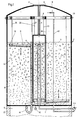
- FIG. 1 In the illustrated system for producing biogas from liquid manure, a circular cylindrical container 21 is provided which stands on a foundation 20.
- the manure is pumped from below into the container by means of a pump 22, preferably with the aid of compressed air generated by means of a compressor, via the feed line 2.
- the slurry first enters an inner cylindrical heating zone 1, the wall of which is formed by a heat exchanger 3.
- the heat exchanger 3 is a double-walled room through which, for example, hot water is passed.
- the slurry is pumped in relatively slowly, in batches, but fresh slurry is constantly pumped into the tank, while used slurry constantly leaves the tank, so that the system as a whole is operated continuously. For example, if 10 m3 of liquid manure is generated in a farm every day, a good 0.4 m3 of liquid manure is pumped into the container every hour.
- the manure which is preferably heated to 20 ° -25 ° C., then passes into the ring-shaped acid fermentation chamber 4, in which the pre-fermentation takes place by means of acid bacteria.
- the resulting gases, essentially CO2, H2 and H2S can leave the container through the vent pipe 6.
- the acid fermentation chamber 4 is separated from the main fermentation chamber 10 via the cylindrical wall 15, but the wall 15 ends in the vicinity of the container bottom, so that there is a cylindrical opening 9 to the main fermentation chamber, the pre-fermented manure then passes through the opening 9 into the also annular main fermentation chamber 10.
- a pH measuring device 46 is provided with which the pH of the slurry can be measured when it leaves the acid fermentation chamber.
- the actual fermentation process takes place in this main fermentation chamber 10, in which the biogas is developed with the help of methane bacteria.
- the resulting biogas can escape through a pipe opening in the vicinity of the container ceiling and a discharge line 16, the biogas line being advantageously passed through the container from top to bottom for frost protection reasons.
- the cylindrical outer wall of the main fermentation chamber 10 is designated 34.
- an overflow pipe 41 is provided in the container, which is located in the main fermentation chamber 10 next to the wall 15 to the acid fermentation chamber 4.
- the height of the overflow pipe 41 is determined by the maximum intended filling height of the container.
- the overflow pipe is passed through the tank bottom and has a siphon-like knee 42 in the space under the tank, which prevents the biogas from leaving the tank via the overflow.
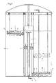
- a roller 8 is mounted in the upper region of the container and can be rotated about its horizontal axis 29 by means of a motor, for example.
- a mixing body two identical concrete slabs 11 are provided for the main fermentation chamber, which are suspended from the roller 8 with ropes 25, 26 and 23, 24, the ropes 25, 26 unwinding from the roller when the roller 8 rotates while simultaneously wind up the ropes 23, 24, on which the other mixing body hangs, so that the left mixing body moves downwards and the right mixing body moves upwards or vice versa.
- a manhole 17 is provided in the container ceiling 13, so that one can look into or get into the container if necessary.
- an annular Mixing body 5 is provided, which is designed as a floating body.
- the floating body can be made of polyester, for example, or an air-filled hollow body made of rubber or the like.
- Ropes 27, 28 are also attached to the floating body 5, which can wind up on the roller 8 and which are guided over lower deflection rollers 7. If the ropes 27, 28 are unwound from the roller when the roller rotates, the floating body 5 can float slowly, thus ensuring that the liquid manure is mixed in the acid fermentation chamber 4 without causing stronger currents which impair the bacteria.
- the suspension of the mixing body makes it possible to move both the mixing body 11 and the floating body 5 simultaneously when the roller rotates and thus to mix the slurry in both fermentation chambers 4, 10 with only one drive.
- the annular mixing body in the interior can, however, also be made of concrete or the like and can be hung directly on the roller 8 with ropes, so that the deflection rollers and the mechanics associated with them can be omitted.
- the design of the mixing bodies means that virtually the entire fermentation chamber is covered. You can also stop the roller 8 and only move the digestate in layers at different heights. Since the degree of fermentation of the digestate in the tank progresses from bottom to top, the digestion phases can be retained. When mixing in the vertical direction, the formation of a floating blanket and any sediment in the container is prevented.
- the method according to the invention thus has the additional advantage over known methods that vaccination of the fermentation medium with a bacterial concentrate can be omitted. Since the fermentation starts immediately without any dead time, the fermentation material can be kept in the main fermentation chamber for a very short time, which is around 2 to 3 days. Since the fermented manure is largely displaced by fresh manure, no fermentation space is lost. Due to the heat exchanger 3, the temperature in the acid fermentation chamber 4 is practically constant. Since the acid bacteria find optimal living conditions, they can reduce the oxygen content of the manure to a minimum. This is also supported in a gentle manner by the uniform mixing with the aid of the floating body 5.
- the plant according to the invention is also suitable for liquid manure with a higher proportion of uncrushed solids and for all fermentable viscous media.
- two identical mixing bodies 11 are provided, the outline of which corresponds to a semi-circular sector, and because of the acid fermentation chamber 4 there is a recess in the form of a semi-circle on the inside.
- the two mixing bodies 11 thus capture almost the entire cross-section of the container except for the remaining edge zones, which the manure flows past when the mixing bodies move.
- the mixing bodies are each suspended on three ropes 25, 26, 32, wherein the suspension points 30, 31, 33 can be arranged, for example, on a circular arc, the center of which is the container axis.
- One of the suspension points 30 is almost there below the roller, so that the rope 25 hangs approximately vertically, while the other two ropes 26, 32 are guided obliquely.
- a uniform winding of the three ropes on the roller and thus a smooth movement can be achieved because of the different lengths of the ropes 25 on the one hand and 26 and 32 on the other hand by varying the thickness of the roller.
- the mixing bodies have a circumferential vertical upstand 12, for example in the form of a sheet metal, but the central circular region 18 in each case has no upstand.
- Fig. 3 shows a mixing body 11 for the main fermentation chamber, which is designed as a concrete slab.
- the concrete slab is preferably suspended in the container with the ropes 25, 32 such that the slab has an angle of inclination ⁇ of a few degrees to the horizontal.
- hot water pipes 35 are laid as a heating device, for example in the manner of an underfloor heating system.
- the hot water is supplied and discharged by means of the hoses 36.
- the ropes of the suspension device 25, 32 are fastened to the mixing body 11 via anchors 30, 33, which are cast, for example, in concrete.
- the mixing body plate 11 has a circumferential upstand 12 made of concrete in the form of a sheet.
- Fig. 4 shows an enlarged view of the roller 8, on which the tethers for the mixing body are wound.
- the roller 8 rotates about its horizontal axis 29.
- the ropes are fastened to the roller at their end points 38, 39 by suitable fastening means. So that a smooth winding the ropes 26, 32 is guaranteed on the roller, it is better if the ropes are wound in such a way that in the direction of the roller axis a winding of the rope 26 is alternately followed by a winding of the rope 32.
- the ropes 26, 32 then wind up cleanly next to one another and not one above the other, which would lead to jamming of the ropes. It is so that the rope 32, which winds up on the roller when the roller rotates clockwise as shown in FIG. 5, forms a guide for the other rope 26, so that a clean winding of the ropes takes place side by side.
- FIG. 6, once again illustrates the flow conditions in the container when the mixing bodies move.
- the slurry flows when the float 5 moves downward in the direction of the arrow, laterally past the float 5 in an upward movement and thus counteracts the slurry freshly entering the fermentation chamber 4 at the upper end of the heating zone 1. Since fresh slurry is constantly pumped in, the slurry flows at the lower end of the acid fermentation chamber through the opening 9 into the main fermentation chamber 10. It is now important that the slurry is prevented from following along the wall between the two fermentation chambers in the shortest way flows at the top and thus reaches the overflow pipe 41. The dwell time of this liquid manure in the container would then be too short for sufficient fermentation.
- the mixing bodies 11 have the upstand 12 at the edges, which does not exist in the area of the inner circular arc, so that the mixing body plate is flat in this area 18.
- the manure flowing through the opening 9 into the main fermentation chamber 10 flows through under the plate when the mixing body plate 11 is at the level of the opening, in the container radially outwards and past the mixing body there.
- the inflowing fresh liquid manure thus quickly reaches the outer edge zones of the container 43, in which old liquid manure is located, and displaces them.
- Due to the upstand 12 at the edge of the mixing body the reverse flow does not occur from the outside over the edge of the upstand, in which the flow resistance would be significantly higher.
- the special design of the mixing body therefore ensures a practically 100% digestion rate of the digestate.
- the heating of the slurry via the mixing bodies which come into contact with the slurry in all areas of the container, prevents the formation of cold or heat pockets.
- the mixing bodies move downwards (see left mixing body in the illustration according to FIG. 6), the slurry flows on both sides of the mixing body, i.e. inside and outside, past and under the plate radially from the middle of the plate inwards and outwards but above the plate radially from the outside and inside to the center of the plate.
- the slurry flows under the plate from the inside to the outside (see also arrows 48 in FIG. 2) and radially inwards over the plate from the upstand (see also arrows 47 in Fig. 2).
- the mixing body has a slight inclination towards the center of the container, the flow from the outside to the inside is intensified. In this way, the effect described above, which effects the uniform mixing of fresh manure with the old manure located in the outer zones, is supported.
- the mixing of the manure by moving the plate-shaped mixing body 11 in the vertical direction has the following further advantage.
- the bacteria develop their metabolite methane, millions of very small bubbles form. Because of the solids content in the slurry, these tiny bubbles with their low buoyancy cannot rise up in the tank quickly enough. There is therefore a risk that the metabolic product of the bacteria will accumulate in the entire fermentation area. This worsens the living conditions of the bacteria and can lead to the death of the bacteria. It is therefore desirable to remove the metabolic product as quickly as possible.
- the plate-shaped mixing bodies have a large surface area and, when the mixing bodies move, the tiny bubbles come into contact with the heated plates, small bubbles are combined to form larger bubbles on the plate surfaces.
- the larger vesicles have a higher buoyancy, which makes it easier to climb up and the emptying of the container with the metabolic product of the bacteria, i.e. the biogas, is accelerated.
- the size of the bubbles increasing from bottom to top is indicated in the illustration according to FIG. 1.
- the thickness of the slurry layer mixed above or below the mixing body can be determined by the speed of the vertical movement of the mixing body.
- the mixing bodies move slowly, only a layer of small thickness (height) above and below the mixing body plates is moved and mixed. With faster movement, this thickness of the moving layer increases.
- this quasi-layer-by-layer mixing the slurry layers with different phases of decay depending on the distance from the tank bottom are retained in layers.
- a standing, essentially circular-cylindrical container is assumed.
- the container may as well have a rectangular or polygonal cross section.
- the container according to the invention does not have to be upright, but rather can also be designed to be horizontal, similar to a heating oil tank, for example.
- the mixing bodies for mixing the liquid manure are also designed as plates and slowly moved in the tank in the axial direction. In this case it is not possible to hang the mixing elements on ropes in the container. Instead, however, the mixing bodies can be moved in the container with the aid of rails arranged in the container and suitable drive means. The mixing bodies are then guided in the rails and displaced in the axial direction by the drive means. The mixing then takes place in an analogous manner to that of the container shown in FIGS. 1 and 6, so that the advantages of the mixing described above are also given in such a system.
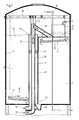
- the container 21 consists of the acid fermentation chamber 50 and the main fermentation chamber 51, which are separated from one another by a partition wall 56 which runs across the container.
- the acid fermentation chamber 50 is closed at the top by a cover blanket 52.
- This blanket closes there is a bell 65 on the side, the upper wall of which is higher than the sealing cover 52.
- This bell essentially serves as a foam trap.
- the resulting in the acid fermentation chamber 50 unusable gases, namely in the main CO2, H2 and H2S, can escape in the chamber upwards via the bell 65 and a gas discharge pipe 64 from the container 21.
- the manure is first pumped into the container via the feed pipe 53.
- the feed pipe 53 is arranged somewhat laterally from the center of the container.
- the pumped manure rises in this pipe until it has reached the branch to the pipe 55 and then flows via the pipe 55 into the acid fermentation chamber 50.
- the fermentation tank is equipped with a pressure relief valve.
- a mixing body 57 is also already provided for the feed pipe 53 and is likewise suspended on the roller 63 in the container. This mixing body is also preferably made of concrete.
- the mixing body is approximately cylindrical due to the narrowness of the tube and has a conical tip, that is to say roughly the shape of a grenade overall. If the mixing body 57 is made of concrete, the dead weight is usually sufficient to mix the slurry in the feed pipe 53 when it is lowered, even if it contains solid parts. By mixing the slurry in the supply pipe, temperature compensation is also achieved in the pipe and a temperature profile from the inside to the outside is prevented. This optimizes the heat exchange between the cooler fresh manure in the feed pipe and the warmer old manure in the outlet pipe 59. The acid fermentation then takes place in the acid fermentation chamber. If this acid fermentation is to be aerobic, the slurry becomes vented in the acidic fermentation chamber 50 via the plate-shaped mixing body 61 suspended there.
- Pipes 67 are laid in this mixing body 61 with connecting pieces which have openings to the surface of the mixing body. It is advantageous if means are provided to close the air outlet openings on the surface of the mixing body so that no manure can penetrate the air lines.
- the pipelines 67 in the mixing body are supplied with air or oxygen via drag hoses 68 which are connected to it and lead out of the mixing body 61.
- drag hoses are known in principle from, for example, hydraulic hoses in elevators.
- the drag hoses 68 are used because the mixing body plate 61 is moved up and down in the container by means of the ropes and the hoses must not be a hindrance during this movement.
- the manure can leave the acid fermentation chamber 50 via an opening in the partition 56 near the bottom of the container.
- This connection opening 69 is relatively small, for example in the case of a rectangular design, approximately 20 cm ⁇ 30 cm, so that no undesired mixing of the slurry from the acid fermentation chamber 50 with the slurry from the main fermentation chamber 51 occurs.
- Two such connection openings can also be provided, which are located to the right and left of the feed pipe 53.
- the manure thus enters the main fermentation chamber 51 near the bottom, where the actual methane fermentation begins.
- the developing biogas rises in the main fermentation chamber 51 and is in turn collected by a methane drain pipe 16 and discharged from the container.
- the methane drain pipe can, as in the embodiment of FIG.
- the liquid level 70 in the main fermentation chamber can be so high that the sealing cover 52 of the acid fermentation chamber 50 is covered.
- the level of the liquid in the main fermentation chamber 51 is determined by a drain pipe 59 for the fermented slurry of the main fermentation chamber.
- This drain pipe 59 is designed as an overflow pipe, so that the fermented slurry of the main fermentation chamber runs into this drain pipe at the top.
- the drain pipe 59 is arranged concentrically around the inlet pipe 53 for the liquid manure, which leads to the acid fermentation chamber 50. The manure then runs through the outlet 58.
- the concentric arrangement of the drain pipe around the inlet pipe has the advantage that a direct heat exchange takes place between the cooler fresh manure and the warm used manure via the wall of the inlet pipe 53.
- a direct heat exchange takes place between the cooler fresh manure and the warm used manure via the wall of the inlet pipe 53.
- the viscous consistency of the manure which also contains solid particles, there is no thermal circulation and therefore no adequate heat compensation from the outside in, so that heating via the pipe wall of the inlet pipe 53 alone is not sufficient. So that the heat exchange between the old liquid manure and the fresh liquid manure via the pipe wall of the pipe 53 is effective, it is imperative that the old liquid manure is mixed in the drain pipe 59.
- one or more concrete mixing bodies 62 are provided for the mixing of the slurry in the annular space of the drain pipe 59.
- the fresh manure is thus already preheated via the feed pipe 53 into the acid fermentation chamber 50, for this Preheating the heat generated during the fermentation processes can be used.
- the concrete mixing body 62 is also suspended from the roller 63 by a rope and is moved up and down in the container.
- a sand cutter 66 is preferably arranged in the bottom of the fermentation tank 21 in the area of the connection openings 69 in the partition between the two fermentation chambers, which catches the separated sludge and sand fractions from the manure.
- the flow conditions in the container according to the embodiment according to FIGS. 7 and 8 are similar to those in the system according to FIGS. 1 and 6. In the illustration according to FIGS.
- FIG. 9 shows a section through the mixing body 61, which is provided for the acid fermentation chamber 50 according to FIG. 7.
- the air is introduced or discharged via the to the Mixing body connected drag hoses 68.
- the hoses 68 are connected to pipes 67 through which air is passed, which are laid in the mixing body. So that the slurry can be aerated at the top or bottom of the mixing body, connecting pieces 71 with an opening to the top or bottom of the mixing body plate branch off from the tubes 67.
- the mixing body plate 61 can be covered with a screen film. This screen film has very fine openings of, for example, 10-15 ⁇ m, so that no manure can penetrate through it.
Landscapes
- Health & Medical Sciences (AREA)
- Chemical & Material Sciences (AREA)
- Life Sciences & Earth Sciences (AREA)
- Engineering & Computer Science (AREA)
- Wood Science & Technology (AREA)
- Zoology (AREA)
- Organic Chemistry (AREA)
- Bioinformatics & Cheminformatics (AREA)
- Genetics & Genomics (AREA)
- General Engineering & Computer Science (AREA)
- General Health & Medical Sciences (AREA)
- Sustainable Development (AREA)
- Biomedical Technology (AREA)
- Biotechnology (AREA)
- Biochemistry (AREA)
- Microbiology (AREA)
- Molecular Biology (AREA)
- Analytical Chemistry (AREA)
- Physics & Mathematics (AREA)
- Thermal Sciences (AREA)
- Clinical Laboratory Science (AREA)
- General Chemical & Material Sciences (AREA)
- Oil, Petroleum & Natural Gas (AREA)
- Treatment Of Sludge (AREA)
- Apparatus Associated With Microorganisms And Enzymes (AREA)
Priority Applications (1)
| Application Number | Priority Date | Filing Date | Title |
|---|---|---|---|
| AT87112084T ATE81669T1 (de) | 1987-03-02 | 1987-08-20 | Verfahren und anlage zur herstellung von biogas aus dickfluessigen vergaerbaren medien. |
Applications Claiming Priority (2)
| Application Number | Priority Date | Filing Date | Title |
|---|---|---|---|
| DE3706699 | 1987-03-02 | ||
| DE3706699 | 1987-03-02 |
Publications (3)
| Publication Number | Publication Date |
|---|---|
| EP0280762A2 true EP0280762A2 (fr) | 1988-09-07 |
| EP0280762A3 EP0280762A3 (en) | 1989-07-19 |
| EP0280762B1 EP0280762B1 (fr) | 1992-10-21 |
Family
ID=6322117
Family Applications (1)
| Application Number | Title | Priority Date | Filing Date |
|---|---|---|---|
| EP87112084A Expired - Lifetime EP0280762B1 (fr) | 1987-03-02 | 1987-08-20 | Procédé et appareil pour la production de biogaz à partir de milieux épais fermentescibles |
Country Status (4)
| Country | Link |
|---|---|
| EP (1) | EP0280762B1 (fr) |
| AT (1) | ATE81669T1 (fr) |
| DD (1) | DD269377A5 (fr) |
| DE (1) | DE3782333D1 (fr) |
Cited By (4)
| Publication number | Priority date | Publication date | Assignee | Title |
|---|---|---|---|---|
| WO2002094978A3 (fr) * | 2001-05-22 | 2003-12-04 | Xaver Lipp | Dispositif et procede pour la fermentation de substances organiques |
| CN113975988A (zh) * | 2015-12-29 | 2022-01-28 | 生命科技股份有限公司 | 具有侧向移位的柔性驱动线的流体混合系统及使用方法 |
| CN117946840A (zh) * | 2024-03-26 | 2024-04-30 | 诸城市华邦机械有限公司 | 一种食用菌酵素的生产设备 |
| CN119174514A (zh) * | 2024-10-29 | 2024-12-24 | 湖北中烟工业有限责任公司 | 一种无氧或厌氧烟叶发酵设备 |
Families Citing this family (1)
| Publication number | Priority date | Publication date | Assignee | Title |
|---|---|---|---|---|
| AT407523B (de) * | 1996-12-20 | 2001-04-25 | En Service Gmbh | Biogasfermenteranlage |
Family Cites Families (3)
| Publication number | Priority date | Publication date | Assignee | Title |
|---|---|---|---|---|
| FR994032A (fr) * | 1944-12-09 | 1951-11-09 | Procédé et dispositifs pour la production intensive du méthane par fermentation | |
| DE3102739C2 (de) * | 1981-01-28 | 1983-10-20 | Messerschmitt-Bölkow-Blohm GmbH, 8000 München | Verfahren und Vorrichtung zur anaeroben Aufbereitung von Abfall |
| CH657150A5 (en) * | 1982-08-06 | 1986-08-15 | Inventa Ag | Biogas reactor |
-
1987
- 1987-08-20 AT AT87112084T patent/ATE81669T1/de not_active IP Right Cessation
- 1987-08-20 EP EP87112084A patent/EP0280762B1/fr not_active Expired - Lifetime
- 1987-08-20 DE DE8787112084T patent/DE3782333D1/de not_active Expired - Lifetime
-
1988
- 1988-03-01 DD DD88313284A patent/DD269377A5/de not_active IP Right Cessation
Cited By (5)
| Publication number | Priority date | Publication date | Assignee | Title |
|---|---|---|---|---|
| WO2002094978A3 (fr) * | 2001-05-22 | 2003-12-04 | Xaver Lipp | Dispositif et procede pour la fermentation de substances organiques |
| CN113975988A (zh) * | 2015-12-29 | 2022-01-28 | 生命科技股份有限公司 | 具有侧向移位的柔性驱动线的流体混合系统及使用方法 |
| CN117946840A (zh) * | 2024-03-26 | 2024-04-30 | 诸城市华邦机械有限公司 | 一种食用菌酵素的生产设备 |
| CN117946840B (zh) * | 2024-03-26 | 2024-05-31 | 诸城市华邦机械有限公司 | 一种食用菌酵素的生产设备 |
| CN119174514A (zh) * | 2024-10-29 | 2024-12-24 | 湖北中烟工业有限责任公司 | 一种无氧或厌氧烟叶发酵设备 |
Also Published As
| Publication number | Publication date |
|---|---|
| DD269377A5 (de) | 1989-06-28 |
| DE3782333D1 (de) | 1992-11-26 |
| EP0280762B1 (fr) | 1992-10-21 |
| EP0280762A3 (en) | 1989-07-19 |
| ATE81669T1 (de) | 1992-11-15 |
Similar Documents
| Publication | Publication Date | Title |
|---|---|---|
| DE4110908C2 (de) | Vorrichtung zum Aufrechterhalten einer kontinuierlichen Mischung in einer Flüssigkeit, die Feststoffe und Gas enthält und zum gleichzeitigen Abtrennen von Gas oder von Gas und Feststoffen von der Flüssigkeit | |
| DE2135762C3 (de) | Verfahren zum aeroben Fermentieren und Fermentierungsvorrichtung | |
| EP2878365B1 (fr) | Agitateur pour un digesteur à biogaz | |
| EP0153299A1 (fr) | Procédé et dispositif pour le traitement anaérobie de substrats organiques | |
| EP0113719B1 (fr) | Dispositif pour la production de gaz biologique | |
| AT407523B (de) | Biogasfermenteranlage | |
| DE202006004982U1 (de) | Rührwerk für Fermentationsbehälter | |
| DE3411264A1 (de) | Verfahren und vorrichtung zur erzeugung von biogas | |
| DE1767577A1 (de) | Verfahren und Vorrichtung zur Malzgewinnung | |
| EP0280762B1 (fr) | Procédé et appareil pour la production de biogaz à partir de milieux épais fermentescibles | |
| EP0998430A1 (fr) | Procede et dispositif pour le traitement biologique d'un fluide avec production de biogaz | |
| DE3737870A1 (de) | Verfahren und anlage zur herstellung von biogas aus dickfluessigen vergaerbaren medien | |
| EP0025571B1 (fr) | Procédé et appareil pour améliorer l'efficacité du mélange de milieux liquides, en particulier de milieux visqueux | |
| DE3232530A1 (de) | Biohochleistungsdurchlaufreaktor | |
| WO2008128631A2 (fr) | Installation biogaz pour produire du biogaz par fermentation humide anaérobie d'un substrat contenant de la biomasse au cours d'un processus à écoulement continu en une étape | |
| EP2624945B1 (fr) | Dispositif et procédé pour chauffer une substance liquide, notamment dispositif d'empâtage pour produire de la bière | |
| DE69129862T2 (de) | Anlage zur behandlung von organischen abfällen und abwasser | |
| DE3327541A1 (de) | Verfahren und vorrichtung zur gewinnung von biogas | |
| DE3100324A1 (de) | Vorrichtung zur umsetzung von biomasse in energie | |
| DE2502515A1 (de) | Photosynthesereaktor und dessen verwendung | |
| CH657150A5 (en) | Biogas reactor | |
| EP0121729B1 (fr) | Réacteur biologique à déplacement de haut rendement | |
| AT394544B (de) | Vorrichtung zur entsorgung, insbesondere hygienisierung, des in einer klaeranlage anfallenden schlammes | |
| EP0046442A1 (fr) | Etable circulaire | |
| EP2392642B1 (fr) | Procédé destiné à produire du biogaz |
Legal Events
| Date | Code | Title | Description |
|---|---|---|---|
| PUAI | Public reference made under article 153(3) epc to a published international application that has entered the european phase |
Free format text: ORIGINAL CODE: 0009012 |
|
| AK | Designated contracting states |
Kind code of ref document: A2 Designated state(s): AT BE CH DE FR GB LI LU NL SE |
|
| PUAL | Search report despatched |
Free format text: ORIGINAL CODE: 0009013 |
|
| AK | Designated contracting states |
Kind code of ref document: A3 Designated state(s): AT BE CH DE FR GB LI LU NL SE |
|
| 17P | Request for examination filed |
Effective date: 19890824 |
|
| 17Q | First examination report despatched |
Effective date: 19920123 |
|
| GRAA | (expected) grant |
Free format text: ORIGINAL CODE: 0009210 |
|
| AK | Designated contracting states |
Kind code of ref document: B1 Designated state(s): AT BE CH DE FR GB LI LU NL SE |
|
| REF | Corresponds to: |
Ref document number: 81669 Country of ref document: AT Date of ref document: 19921115 Kind code of ref document: T |
|
| REF | Corresponds to: |
Ref document number: 3782333 Country of ref document: DE Date of ref document: 19921126 |
|
| GBT | Gb: translation of ep patent filed (gb section 77(6)(a)/1977) |
Effective date: 19930114 |
|
| ET | Fr: translation filed | ||
| PLBE | No opposition filed within time limit |
Free format text: ORIGINAL CODE: 0009261 |
|
| STAA | Information on the status of an ep patent application or granted ep patent |
Free format text: STATUS: NO OPPOSITION FILED WITHIN TIME LIMIT |
|
| PG25 | Lapsed in a contracting state [announced via postgrant information from national office to epo] |
Ref country code: LU Free format text: LAPSE BECAUSE OF NON-PAYMENT OF DUE FEES Effective date: 19930831 |
|
| 26N | No opposition filed | ||
| PG25 | Lapsed in a contracting state [announced via postgrant information from national office to epo] |
Ref country code: DE Effective date: 19940503 |
|
| EAL | Se: european patent in force in sweden |
Ref document number: 87112084.6 |
|
| PGFP | Annual fee paid to national office [announced via postgrant information from national office to epo] |
Ref country code: GB Payment date: 19990920 Year of fee payment: 13 |
|
| PG25 | Lapsed in a contracting state [announced via postgrant information from national office to epo] |
Ref country code: GB Free format text: LAPSE BECAUSE OF NON-PAYMENT OF DUE FEES Effective date: 20000820 |
|
| GBPC | Gb: european patent ceased through non-payment of renewal fee |
Effective date: 20000820 |
|
| PGFP | Annual fee paid to national office [announced via postgrant information from national office to epo] |
Ref country code: AT Payment date: 20040810 Year of fee payment: 18 |
|
| PGFP | Annual fee paid to national office [announced via postgrant information from national office to epo] |
Ref country code: FR Payment date: 20040812 Year of fee payment: 18 |
|
| PGFP | Annual fee paid to national office [announced via postgrant information from national office to epo] |
Ref country code: CH Payment date: 20040818 Year of fee payment: 18 |
|
| PGFP | Annual fee paid to national office [announced via postgrant information from national office to epo] |
Ref country code: SE Payment date: 20040819 Year of fee payment: 18 Ref country code: NL Payment date: 20040819 Year of fee payment: 18 |
|
| PGFP | Annual fee paid to national office [announced via postgrant information from national office to epo] |
Ref country code: BE Payment date: 20040916 Year of fee payment: 18 |
|
| PG25 | Lapsed in a contracting state [announced via postgrant information from national office to epo] |
Ref country code: AT Free format text: LAPSE BECAUSE OF NON-PAYMENT OF DUE FEES Effective date: 20050820 |
|
| PG25 | Lapsed in a contracting state [announced via postgrant information from national office to epo] |
Ref country code: SE Free format text: LAPSE BECAUSE OF NON-PAYMENT OF DUE FEES Effective date: 20050821 |
|
| PG25 | Lapsed in a contracting state [announced via postgrant information from national office to epo] |
Ref country code: LI Free format text: LAPSE BECAUSE OF NON-PAYMENT OF DUE FEES Effective date: 20050831 Ref country code: CH Free format text: LAPSE BECAUSE OF NON-PAYMENT OF DUE FEES Effective date: 20050831 Ref country code: BE Free format text: LAPSE BECAUSE OF NON-PAYMENT OF DUE FEES Effective date: 20050831 |
|
| PG25 | Lapsed in a contracting state [announced via postgrant information from national office to epo] |
Ref country code: NL Free format text: LAPSE BECAUSE OF NON-PAYMENT OF DUE FEES Effective date: 20060301 |
|
| REG | Reference to a national code |
Ref country code: CH Ref legal event code: PL |
|
| EUG | Se: european patent has lapsed | ||
| PG25 | Lapsed in a contracting state [announced via postgrant information from national office to epo] |
Ref country code: FR Free format text: LAPSE BECAUSE OF NON-PAYMENT OF DUE FEES Effective date: 20060428 |
|
| NLV4 | Nl: lapsed or anulled due to non-payment of the annual fee |
Effective date: 20060301 |
|
| REG | Reference to a national code |
Ref country code: FR Ref legal event code: ST Effective date: 20060428 |
|
| BERE | Be: lapsed |
Owner name: *FRESE CHRISTOPH Effective date: 20050831 |