EP0280766A2 - Procédé et installation de coulée continue sous laitier électro conducteur d'aciers et d'alliages - Google Patents
Procédé et installation de coulée continue sous laitier électro conducteur d'aciers et d'alliages Download PDFInfo
- Publication number
- EP0280766A2 EP0280766A2 EP87114823A EP87114823A EP0280766A2 EP 0280766 A2 EP0280766 A2 EP 0280766A2 EP 87114823 A EP87114823 A EP 87114823A EP 87114823 A EP87114823 A EP 87114823A EP 0280766 A2 EP0280766 A2 EP 0280766A2
- Authority
- EP
- European Patent Office
- Prior art keywords
- slag
- mold
- electrically conductive
- liquid
- heated
- Prior art date
- Legal status (The legal status is an assumption and is not a legal conclusion. Google has not performed a legal analysis and makes no representation as to the accuracy of the status listed.)
- Withdrawn
Links
Images
Classifications
-
- B—PERFORMING OPERATIONS; TRANSPORTING
- B22—CASTING; POWDER METALLURGY
- B22D—CASTING OF METALS; CASTING OF OTHER SUBSTANCES BY THE SAME PROCESSES OR DEVICES
- B22D11/00—Continuous casting of metals, i.e. casting in indefinite lengths
- B22D11/10—Supplying or treating molten metal
- B22D11/11—Treating the molten metal
-
- C—CHEMISTRY; METALLURGY
- C22—METALLURGY; FERROUS OR NON-FERROUS ALLOYS; TREATMENT OF ALLOYS OR NON-FERROUS METALS
- C22B—PRODUCTION AND REFINING OF METALS; PRETREATMENT OF RAW MATERIALS
- C22B9/00—General processes of refining or remelting of metals; Apparatus for electroslag or arc remelting of metals
- C22B9/16—Remelting metals
- C22B9/18—Electroslag remelting
Definitions
- the invention relates to a method for the continuous casting of steels, in particular tool steels, such as, for example, high-speed steels, ledeburitic Cr steels, steels for cold and hot work, etc., from a warming or distribution vessel into a - in particular water-cooled, open at the bottom, straight or curved - mold from which the partially solidified strand is withdrawn continuously or step by means of a pull-out device.
- tool steels such as, for example, high-speed steels, ledeburitic Cr steels, steels for cold and hot work, etc.
- the invention also relates to a device for carrying out this method.
- the electro-slag remelting of self-consumable electrodes enables the production of remelting blocks with a good surface at a slow block build-up speed.
- the shallow sump depths that occur lead to a uniform solidification between the edge and core and thus to a good internal quality of the remelted blocks.
- the use of short molds with lowerable base plates and electrode changes also allows the production of relatively long strands. In the production of small dimensions, however, the production of the required consumable electrodes becomes difficult, and the process costs due to the then low remelting rates become high.
- liquid metal can be made available from a heated pan at a constant temperature over a long period of time.
- the object of the invention is to avoid the respective disadvantages of the above-described methods by means of suitable measures and, if possible, to utilize their advantages.
- the aim is the continuous production of strands with a good surface at casting speeds that are significantly lower than those required and customary in continuous casting, which means that a sufficiently good core zone can also be expected.
- the solution to this problem is that the liquid metal level is completely covered by an overheated, electrically conductive liquid slag, the slag is additionally heated and the liquid steel is poured through the liquid slag, the casting speed being set so that it is at least 1 5 times the usual remelting rates for electroslag remelting and a maximum of 50% of the usual casting speed for continuous casting.
- the inventor took advantage of the knowledge to lower the casting speed during continuous casting that excellent block surfaces can be achieved with electro-slag remelting at still considerably low block build-up speeds, since the surface of the liquid steel in the mold is kept warm by heated slag, so that the slag progresses Freezing over the meniscus is prevented.
- the pouring rate in kg / h should be at least 1.5 times the diameter in the case of round strands or the length of the side in the square or the mean of the short and long side length in the case of rectangular strands in mm.
- the maximum pouring rate should be so low that a depth of the liquid sump of 4 m is not exceeded.
- the layer thickness of the electrically conductive slag should be at least 20 mm according to a further feature of the invention.
- the slag can be heated by one or more non-consumable electrodes made of graphite, tungsten, molybdenum or other high-melting electrically conductive materials which are connected to a power source.
- the slag bath can also be heated by a plasma torch.
- molds as are common in continuous casting, can be used to carry out the method.
- small cross sections - such as 100 mm and less - it becomes difficult to arrange one or more electrodes in addition to the pouring stream in the mold.
- the second pole can also be formed by the liquid metal running from an upstream distributor, the power supply being able to do this via electrodes built into the distributor wall.
- Another possibility is to also cover the distributor with an electrically conductive slag and also to produce the power supply there via an electrode immersed in the slag.
- the second pole can also be formed by a second electrode immersed in the slag bath in the mold.
- the strand can be withdrawn from the mold continuously or step by step.
- a step-by-step strand withdrawal is selected when the mold is stationary, and a return stroke step can be connected to each withdrawal step.
- the mold carries out an oscillating movement in such a way that the strand is briefly overtaken by the mold when moving in the strand withdrawal direction.
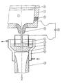
- a pouring jet 4 runs from a spout 5 into a water-cooled funnel mold 6, which is open at the bottom, from a bricked-up distribution vessel 1, in which there is liquid metal 3 under a covering layer of covering slag 2.
- a metal mirror 7 of a strand 12 is superimposed therein with an electrically conductive, overheated slag 8, in which a tubular graphite electrode 9 is immersed. This is connected to a power source 10.
- the second pole of the current source 10 is an electrode 11 installed in the distributor, from where the current flow via the liquid metal 3 into the funnel mold 6 and through the slag 8 to the graphite electrode 9.
- the strand 12 formed in the funnel mold 6 is drawn off downwards.
Landscapes
- Engineering & Computer Science (AREA)
- Chemical & Material Sciences (AREA)
- Mechanical Engineering (AREA)
- Manufacturing & Machinery (AREA)
- Materials Engineering (AREA)
- Metallurgy (AREA)
- Organic Chemistry (AREA)
- Continuous Casting (AREA)
- Manufacture And Refinement Of Metals (AREA)
Applications Claiming Priority (2)
| Application Number | Priority Date | Filing Date | Title |
|---|---|---|---|
| AT46387A AT399463B (de) | 1987-03-03 | 1987-03-03 | Verfahren zum elektroschlacke-stranggiessen von stählen und legierungen |
| AT463/87 | 1987-03-03 |
Publications (2)
| Publication Number | Publication Date |
|---|---|
| EP0280766A2 true EP0280766A2 (fr) | 1988-09-07 |
| EP0280766A3 EP0280766A3 (fr) | 1989-02-22 |
Family
ID=3491291
Family Applications (1)
| Application Number | Title | Priority Date | Filing Date |
|---|---|---|---|
| EP87114823A Withdrawn EP0280766A3 (fr) | 1987-03-03 | 1987-10-10 | Procédé et installation de coulée continue sous laitier électro conducteur d'aciers et d'alliages |
Country Status (3)
| Country | Link |
|---|---|
| EP (1) | EP0280766A3 (fr) |
| AT (1) | AT399463B (fr) |
| DE (1) | DE3734339A1 (fr) |
Cited By (5)
| Publication number | Priority date | Publication date | Assignee | Title |
|---|---|---|---|---|
| EP0786531A1 (fr) * | 1996-01-29 | 1997-07-30 | Inteco Internationale Technische Beratung Gesellschaft mbH | Procédé et dispositif pour la refusion de métaux sous forme de barres |
| AT406239B (de) * | 1996-04-09 | 2000-03-27 | Inteco Int Techn Beratung | Wassergekühlte kokille für das stranggiessen oder elektroschlacke-umschmelzen |
| CN102089101A (zh) * | 2008-07-04 | 2011-06-08 | 阿勒里斯铝业科布伦茨有限公司 | 复合锭的铸造方法 |
| CN102941323A (zh) * | 2012-12-12 | 2013-02-27 | 济钢集团有限公司 | 中薄板坯连铸机结晶器低液位快速变更换中间包的方法 |
| CN110548840A (zh) * | 2019-10-09 | 2019-12-10 | 辽宁科技大学 | 在连铸过程中向结晶器加入加热固态保护渣的装置及方法 |
Families Citing this family (1)
| Publication number | Priority date | Publication date | Assignee | Title |
|---|---|---|---|---|
| AT408528B (de) | 1999-06-08 | 2001-12-27 | Inteco Int Techn Beratung | Verfahren und vorrichtung zur kontinuierlichen herstellung von gegossenen oder umgeschmolzenen strängen nach einem elektroschlacke-verfahren |
Family Cites Families (6)
| Publication number | Priority date | Publication date | Assignee | Title |
|---|---|---|---|---|
| DE1483646A1 (de) * | 1965-06-11 | 1969-09-25 | Suedwestfalen Ag Stahlwerke | Verfahren und Vorrichtung zum Herstellen von Gussbloecken,vorzugsweise Stahlbloecken |
| FR1513573A (fr) * | 1967-01-06 | 1968-02-16 | Soc Metallurgique Imphy | Procédé et dispositif pour l'affinage du métal dans une installation de coulée continue |
| SE332833B (sv) * | 1968-06-27 | 1977-09-19 | Asea Ab | Kokill for tillverkning av got av stal och metallegeringar genom elektroslaggraffineringsmetoden |
| SE364648B (fr) * | 1970-12-04 | 1974-03-04 | Asea Ab | |
| AT330389B (de) * | 1973-11-08 | 1976-06-25 | Voest Ag | Verfahren zum kontinuierlichen giessen von stahlstrangen, insbesondere brammen, in einer stranggiessanlage |
| GB2038367B (en) * | 1978-10-12 | 1982-09-29 | Nippon Steel Corp | Controlling the aluminium content of continuously cast silicon steels |
-
1987
- 1987-03-03 AT AT46387A patent/AT399463B/de not_active IP Right Cessation
- 1987-10-10 EP EP87114823A patent/EP0280766A3/fr not_active Withdrawn
- 1987-10-12 DE DE19873734339 patent/DE3734339A1/de not_active Withdrawn
Cited By (8)
| Publication number | Priority date | Publication date | Assignee | Title |
|---|---|---|---|---|
| EP0786531A1 (fr) * | 1996-01-29 | 1997-07-30 | Inteco Internationale Technische Beratung Gesellschaft mbH | Procédé et dispositif pour la refusion de métaux sous forme de barres |
| AT406384B (de) * | 1996-01-29 | 2000-04-25 | Inteco Int Techn Beratung | Verfahren zum elektroschlacke-strangschmelzen von metallen |
| AT406239B (de) * | 1996-04-09 | 2000-03-27 | Inteco Int Techn Beratung | Wassergekühlte kokille für das stranggiessen oder elektroschlacke-umschmelzen |
| CN102089101A (zh) * | 2008-07-04 | 2011-06-08 | 阿勒里斯铝业科布伦茨有限公司 | 复合锭的铸造方法 |
| CN102089101B (zh) * | 2008-07-04 | 2014-07-09 | 阿勒里斯铝业科布伦茨有限公司 | 复合锭的铸造方法 |
| CN102941323A (zh) * | 2012-12-12 | 2013-02-27 | 济钢集团有限公司 | 中薄板坯连铸机结晶器低液位快速变更换中间包的方法 |
| CN110548840A (zh) * | 2019-10-09 | 2019-12-10 | 辽宁科技大学 | 在连铸过程中向结晶器加入加热固态保护渣的装置及方法 |
| CN110548840B (zh) * | 2019-10-09 | 2024-04-02 | 辽宁科技大学 | 在连铸过程中向结晶器加入加热固态保护渣的装置及方法 |
Also Published As
| Publication number | Publication date |
|---|---|
| DE3734339A1 (de) | 1988-09-15 |
| EP0280766A3 (fr) | 1989-02-22 |
| ATA46387A (de) | 1994-10-15 |
| AT399463B (de) | 1995-05-26 |
Similar Documents
| Publication | Publication Date | Title |
|---|---|---|
| DE19654021C2 (de) | Verfahren zum Umschmelzen von Metallen zu einem Strang sowie Vorrichtung dafür | |
| DE1296747B (de) | Vorrichtung zur Zufuhr einer metallischen Schmelze aus einem Vorratsbehaelter | |
| DE2702061A1 (de) | Kokille zum elektroschlackeschmelzen von metallbloecken mit kantprofil | |
| EP0280766A2 (fr) | Procédé et installation de coulée continue sous laitier électro conducteur d'aciers et d'alliages | |
| DE69818658T2 (de) | Verfahren zur beschichtung mittels des elektroschlackeverfahrens | |
| DE2804487C2 (de) | Vorrichtung zum Auffüllen von Blockköpfen abgegossener Metallblöcke nach dem Elektroschlackenumschmelzverfahren | |
| AT410413B (de) | Verfahren zum elektroschlacke umschmelzen von metallen | |
| DE2355249A1 (de) | Blockgussform, insbesondere zum blockguss beim elektroschlackefeinen | |
| DE1608082C3 (de) | Vorrichtung zum Feinen von Stahl mittel» Schlacke in einer Stranggieß kokille | |
| DE2941849A1 (de) | Verfahren zur herstellung von konstruktionsteilen durch elektro- schlacke-schweissen | |
| DE69912105T2 (de) | Vorrichtung zum giesen von metall | |
| EP1257675B1 (fr) | Procede et systeme pour la production de corps coules creux en metal | |
| DE2807844C2 (de) | Verfahren zum Elektroschlackegießen von Metallblöcken | |
| EP0229589B1 (fr) | Dispositif et procédé de coulée continue de métaux | |
| DE2257104C3 (de) | Einrichtung zum Elektroschlackeschmelzen von Formblöcken | |
| DE2215860C3 (de) | Elektroschlacke-U mschmelzanlage zum Umschmelzen von selbstverzehrenden Elektroden | |
| DE1057291B (de) | Verfahren und Vorrichtung zum Lichtbogenschmelzen von Metallen in einer Stranggusskokille in Zwillingsausfuehrung | |
| AT345488B (de) | Vorrichtung zum gleichzeitigen herstellen von mehreren bloecken mittels elektrischer schmelzung | |
| DE2605645C3 (de) | Verfahren und Vorrichtung zum Elektroschlacke-Umschmelzen | |
| DE2420141C3 (de) | Verfahren und Vorrichtung zum Elektroschlacke-Umschmelzen | |
| DE1952010C3 (de) | Anlage zum Elektroschlacke Gießen hohler Metallblocke | |
| AT345486B (de) | Verfahren und vorrichtung zum elektroschlackenumschmelzen von metallen oder metallegierungen | |
| DE2113521A1 (de) | Elektroschlacke-Umschmelzverfahren und Vorrichtung zu dessen Durchfuehrung | |
| DE2228280C3 (de) | Verfahren zum Elektroschlacke-GieBen von Blöcken | |
| DE2260245C3 (de) | Einrichtung zur Herstellung von Formblöcken |
Legal Events
| Date | Code | Title | Description |
|---|---|---|---|
| PUAI | Public reference made under article 153(3) epc to a published international application that has entered the european phase |
Free format text: ORIGINAL CODE: 0009012 |
|
| AK | Designated contracting states |
Kind code of ref document: A2 Designated state(s): AT BE CH DE ES FR GB GR IT LI LU NL SE |
|
| RBV | Designated contracting states (corrected) |
Designated state(s): AT BE CH DE ES FR GB IT LI LU SE |
|
| PUAL | Search report despatched |
Free format text: ORIGINAL CODE: 0009013 |
|
| AK | Designated contracting states |
Kind code of ref document: A3 Designated state(s): AT BE CH DE ES FR GB IT LI LU SE |
|
| 17P | Request for examination filed |
Effective date: 19890425 |
|
| 17Q | First examination report despatched |
Effective date: 19890915 |
|
| 18W | Application withdrawn |
Withdrawal date: 19900512 |
|
| STAA | Information on the status of an ep patent application or granted ep patent |
Free format text: STATUS: THE APPLICATION HAS BEEN WITHDRAWN |
|
| R18W | Application withdrawn (corrected) |
Effective date: 19900512 |
|
| RIN1 | Information on inventor provided before grant (corrected) |
Inventor name: HOLZGRUBER, WOLFGANG, DIPL.-ING. DR. MONT. Inventor name: HAISSIG, MANFRED, DIPL.-ING. |