EP0280779B1 - Dosimètre personnel avec chambre d'ionisation sur support de circuit intégré - Google Patents
Dosimètre personnel avec chambre d'ionisation sur support de circuit intégré Download PDFInfo
- Publication number
- EP0280779B1 EP0280779B1 EP87118192A EP87118192A EP0280779B1 EP 0280779 B1 EP0280779 B1 EP 0280779B1 EP 87118192 A EP87118192 A EP 87118192A EP 87118192 A EP87118192 A EP 87118192A EP 0280779 B1 EP0280779 B1 EP 0280779B1
- Authority
- EP
- European Patent Office
- Prior art keywords
- dosimeter
- radiation
- dose
- gas
- data
- Prior art date
- Legal status (The legal status is an assumption and is not a legal conclusion. Google has not performed a legal analysis and makes no representation as to the accuracy of the status listed.)
- Expired - Lifetime
Links
- 230000005855 radiation Effects 0.000 claims abstract description 112
- 150000002500 ions Chemical class 0.000 claims abstract description 95
- 230000005684 electric field Effects 0.000 claims abstract description 48
- 238000012546 transfer Methods 0.000 claims abstract description 19
- 230000003750 conditioning effect Effects 0.000 claims abstract 2
- 230000015654 memory Effects 0.000 claims description 28
- 238000001514 detection method Methods 0.000 claims description 26
- 230000008878 coupling Effects 0.000 claims description 11
- 238000010168 coupling process Methods 0.000 claims description 11
- 238000005859 coupling reaction Methods 0.000 claims description 11
- 230000001419 dependent effect Effects 0.000 claims description 10
- 239000000463 material Substances 0.000 claims description 9
- 230000004907 flux Effects 0.000 claims description 7
- 238000005259 measurement Methods 0.000 claims description 7
- 238000012544 monitoring process Methods 0.000 claims description 3
- 230000000007 visual effect Effects 0.000 claims description 3
- 238000013500 data storage Methods 0.000 claims 2
- 230000003139 buffering effect Effects 0.000 claims 1
- 229920003023 plastic Polymers 0.000 abstract description 28
- 239000004033 plastic Substances 0.000 abstract description 28
- 238000004891 communication Methods 0.000 abstract description 15
- 239000000872 buffer Substances 0.000 abstract description 10
- 239000007789 gas Substances 0.000 description 75
- 238000010586 diagram Methods 0.000 description 23
- 210000001519 tissue Anatomy 0.000 description 16
- 239000003990 capacitor Substances 0.000 description 15
- 239000000758 substrate Substances 0.000 description 14
- 238000000034 method Methods 0.000 description 12
- 230000008859 change Effects 0.000 description 8
- 230000006870 function Effects 0.000 description 7
- 230000004044 response Effects 0.000 description 6
- 230000006798 recombination Effects 0.000 description 5
- 238000005215 recombination Methods 0.000 description 5
- XUIMIQQOPSSXEZ-UHFFFAOYSA-N Silicon Chemical compound [Si] XUIMIQQOPSSXEZ-UHFFFAOYSA-N 0.000 description 4
- 230000008901 benefit Effects 0.000 description 4
- 229910052710 silicon Inorganic materials 0.000 description 4
- 239000010703 silicon Substances 0.000 description 4
- 230000033228 biological regulation Effects 0.000 description 3
- 229910052799 carbon Inorganic materials 0.000 description 3
- 230000035945 sensitivity Effects 0.000 description 3
- XKRFYHLGVUSROY-UHFFFAOYSA-N Argon Chemical compound [Ar] XKRFYHLGVUSROY-UHFFFAOYSA-N 0.000 description 2
- IJGRMHOSHXDMSA-UHFFFAOYSA-N Atomic nitrogen Chemical compound N#N IJGRMHOSHXDMSA-UHFFFAOYSA-N 0.000 description 2
- OKTJSMMVPCPJKN-UHFFFAOYSA-N Carbon Chemical compound [C] OKTJSMMVPCPJKN-UHFFFAOYSA-N 0.000 description 2
- RYGMFSIKBFXOCR-UHFFFAOYSA-N Copper Chemical compound [Cu] RYGMFSIKBFXOCR-UHFFFAOYSA-N 0.000 description 2
- 101150007692 DOA4 gene Proteins 0.000 description 2
- 101100387924 Saccharomyces cerevisiae (strain ATCC 204508 / S288c) DOS2 gene Proteins 0.000 description 2
- 101100523544 Schizosaccharomyces pombe (strain 972 / ATCC 24843) raf1 gene Proteins 0.000 description 2
- 101100467517 Schizosaccharomyces pombe (strain 972 / ATCC 24843) raf2 gene Proteins 0.000 description 2
- VYPSYNLAJGMNEJ-UHFFFAOYSA-N Silicium dioxide Chemical compound O=[Si]=O VYPSYNLAJGMNEJ-UHFFFAOYSA-N 0.000 description 2
- 229910000831 Steel Inorganic materials 0.000 description 2
- 231100000987 absorbed dose Toxicity 0.000 description 2
- 230000004888 barrier function Effects 0.000 description 2
- 230000000295 complement effect Effects 0.000 description 2
- 229910052802 copper Inorganic materials 0.000 description 2
- 239000010949 copper Substances 0.000 description 2
- 230000003247 decreasing effect Effects 0.000 description 2
- 238000011161 development Methods 0.000 description 2
- 230000009977 dual effect Effects 0.000 description 2
- 230000000694 effects Effects 0.000 description 2
- PCHJSUWPFVWCPO-UHFFFAOYSA-N gold Chemical compound [Au] PCHJSUWPFVWCPO-UHFFFAOYSA-N 0.000 description 2
- 229910052737 gold Inorganic materials 0.000 description 2
- 239000010931 gold Substances 0.000 description 2
- 238000002955 isolation Methods 0.000 description 2
- 238000004519 manufacturing process Methods 0.000 description 2
- 238000012986 modification Methods 0.000 description 2
- 230000004048 modification Effects 0.000 description 2
- 229910052757 nitrogen Inorganic materials 0.000 description 2
- 230000036961 partial effect Effects 0.000 description 2
- 230000008569 process Effects 0.000 description 2
- 230000001681 protective effect Effects 0.000 description 2
- 239000010959 steel Substances 0.000 description 2
- 230000001960 triggered effect Effects 0.000 description 2
- 208000032953 Device battery issue Diseases 0.000 description 1
- 239000004593 Epoxy Substances 0.000 description 1
- 239000004698 Polyethylene Substances 0.000 description 1
- 238000009825 accumulation Methods 0.000 description 1
- 239000000853 adhesive Substances 0.000 description 1
- 230000001070 adhesive effect Effects 0.000 description 1
- 239000003570 air Substances 0.000 description 1
- 239000004411 aluminium Substances 0.000 description 1
- 229910052782 aluminium Inorganic materials 0.000 description 1
- 229910052786 argon Inorganic materials 0.000 description 1
- 230000005540 biological transmission Effects 0.000 description 1
- WUKWITHWXAAZEY-UHFFFAOYSA-L calcium difluoride Chemical compound [F-].[F-].[Ca+2] WUKWITHWXAAZEY-UHFFFAOYSA-L 0.000 description 1
- 229910001634 calcium fluoride Inorganic materials 0.000 description 1
- 238000004364 calculation method Methods 0.000 description 1
- 239000006229 carbon black Substances 0.000 description 1
- 230000001143 conditioned effect Effects 0.000 description 1
- 238000010276 construction Methods 0.000 description 1
- 125000004122 cyclic group Chemical group 0.000 description 1
- 230000007547 defect Effects 0.000 description 1
- 238000009792 diffusion process Methods 0.000 description 1
- 239000012777 electrically insulating material Substances 0.000 description 1
- 239000007772 electrode material Substances 0.000 description 1
- 238000005516 engineering process Methods 0.000 description 1
- 231100001261 hazardous Toxicity 0.000 description 1
- 229910052739 hydrogen Inorganic materials 0.000 description 1
- 238000002347 injection Methods 0.000 description 1
- 239000007924 injection Substances 0.000 description 1
- 238000009413 insulation Methods 0.000 description 1
- 230000005865 ionizing radiation Effects 0.000 description 1
- 230000000670 limiting effect Effects 0.000 description 1
- 239000000203 mixture Substances 0.000 description 1
- 238000012806 monitoring device Methods 0.000 description 1
- 210000003205 muscle Anatomy 0.000 description 1
- QJGQUHMNIGDVPM-UHFFFAOYSA-N nitrogen group Chemical group [N] QJGQUHMNIGDVPM-UHFFFAOYSA-N 0.000 description 1
- 230000003287 optical effect Effects 0.000 description 1
- 229910052760 oxygen Inorganic materials 0.000 description 1
- 239000002245 particle Substances 0.000 description 1
- 238000002161 passivation Methods 0.000 description 1
- 230000000737 periodic effect Effects 0.000 description 1
- -1 polyethylene Polymers 0.000 description 1
- 229920000573 polyethylene Polymers 0.000 description 1
- 238000012545 processing Methods 0.000 description 1
- 230000009467 reduction Effects 0.000 description 1
- 230000002441 reversible effect Effects 0.000 description 1
- 238000000926 separation method Methods 0.000 description 1
- 235000012239 silicon dioxide Nutrition 0.000 description 1
- 239000000377 silicon dioxide Substances 0.000 description 1
- 230000001360 synchronised effect Effects 0.000 description 1
- XLYOFNOQVPJJNP-UHFFFAOYSA-N water Substances O XLYOFNOQVPJJNP-UHFFFAOYSA-N 0.000 description 1
Images







Classifications
-
- G—PHYSICS
- G01—MEASURING; TESTING
- G01T—MEASUREMENT OF NUCLEAR OR X-RADIATION
- G01T7/00—Details of radiation-measuring instruments
- G01T7/12—Provision for actuation of an alarm
- G01T7/125—Alarm- or controlling circuits using ionisation chambers, proportional counters or Geiger-Mueller tubes, also functioning as UV detectors
-
- G—PHYSICS
- G01—MEASURING; TESTING
- G01T—MEASUREMENT OF NUCLEAR OR X-RADIATION
- G01T1/00—Measuring X-radiation, gamma radiation, corpuscular radiation, or cosmic radiation
- G01T1/16—Measuring radiation intensity
- G01T1/185—Measuring radiation intensity with ionisation chamber arrangements
-
- H—ELECTRICITY
- H01—ELECTRIC ELEMENTS
- H01J—ELECTRIC DISCHARGE TUBES OR DISCHARGE LAMPS
- H01J47/00—Tubes for determining the presence, intensity, density or energy of radiation or particles
- H01J47/02—Ionisation chambers
Definitions
- Ionizing radiation presents a direct hazard to people; therefore, the dose a person receives should be minimized.
- Dose is related to the energy absorbed by the person. Dose minimization is best done by avoiding all unnecessary radiation exposure and minimizing necessary radiation exposure. In any event, the degree of exposure can be controlled if a person monitors his exposure; therefore, a real time warning device, monitoring and alarming the person of radiation exposure, is desirable.
- the devices presently used for detecting and warning of radiation dangers are large and expensive. These features prevent every person at risk from using one on a continual basis.
- Standard radiation monitoring methods film and thermoluminescent detectors (TLD) only record accumulated dose. They do not provide a contemporaneous warning of current radiation exposure but their use is mandated by the government to record accumulated dose of radiation. If a person exceeds his yearly dose, he can no longer work in a radiation area and the person or company responsible is notified accordingly.
- TLD thermoluminescent detectors
- the present invention satisfies the accuracy and non-corruptibility requirements of present radiation monitoring devices, while warning the wearer of the dose rate and total dose at a monetary cost similar to that of the film or TLD badge. In this way, a warning device can be available to all who may be exposed to hazardous radiation.
- a wristwatch dosimeter is disclosed. No provision is made in the wristwatch to determine dose at different skin depths. Also, the wristwatch counts photons. This photon counter is different from the present inventive concept of collecting charged ions. The accuracy of measurement in the wristwatch is a function of the energy of the X-rays.
- tissue equivalent gas in an ion chamber.
- the advantage of tissue equivalent gas is that current measured by the device is accurate in units of rad, or radiation absorbed dose.
- the Arbel monitor does not utilize a volume of gas immediately atop an integrated circuit (IC) and a collector electrode on the surface of the IC in direct contact with the gas. Further, Arbel does not use the collector electrode incorporated within an amplifier in the IC. Also, Arbel uses the logarithm of an amplified signal from the ion chamber.
- the portable monitor consists of a Geiger-Muller tube (GM tube) with an event counter which records the number of ionizing events. There is a readout display and an audio alarm.
- GM tube Geiger-Muller tube
- the problem with the GM tube is that its response is not linear with the energy of the radiation, so its accuracy varies with radiation energy, although it is useful for warning.
- a dosimeter comprising the features according to the preamble of the claim 1 is known from IEEE Transactions on Nuclear Science, August 1979 ("A Multichannel Electrometer Data-Acquisition System").
- This known dosimeter comprises an array of ionization chambers which are closely spaced by about 2 cm.
- An essential disadvantage of this dosimeter can be seen in the separation of the different ionization chamber detectors and their corresponding electrometers. Therefore cables etc. are necessary for the connection of the ionization chambers and the electrometers.
- each electrometer is housed in a cast-aluminium box.
- the dosimeter includes a radiation detection assembly and a detector control and interface unit.
- the detection assembly is a plurality of detection subassemblies.
- Each subassembly includes a hemispheric bubble of electrically conductive tissue equivalent plastic which defines a volume of gas within the bubble.
- the gas is adapted to be ionized by radiation incident thereon.
- An integrated circuit (herein IC) is mounted below the volume of gas.
- a collecting electrode, on the surface of the IC, is in direct contact with the gas and collects ions resulting from the ionization of the gas by the radiation.
- the IC includes an amplifier that incorporates the collecting electrode.
- the detector control and interface unit conditions the signal from the amplifier and buffers that signal.
- the unit includes a sensing amplifier that acts as a comparator, and a counter which is used to control the detection subassembly and to store the signal as radiation dose data.
- the collecting electrode is a control gate for an amplifying transistor in the incorporated amplifier. An electric field within the volume of gas moves ions of one polarity toward the collecting electrode.
- the control gate/collecting electrode is biased to a predetermined level which changes due to the collected ions and therefore the output of the amplifying transistor is a signal representative of the amount of ions collected.
- the signal is applied to the interface and passed to the sense amplifier. When the conditioned signal passes a predetermined threshold, the counter is triggered and is incremented.
- Triggering the counter also commands a circuit to clear or restore a predetermined bias level to the control gate (the collecting electrode) of the amplifying transistor.
- the interface also includes means for transferring the radiation data to an external device upon receipt of a dose transfer command.
- the interface may additionally include a dose and dose rate computer and a memory.
- the voltage level (bias) of the collecting electrode is switched from a high and to a low level or vice versa upon receipt of a triggering pulse, thereby eliminating the need to electrically connect a voltage source to the collecting electrode to clear the accumulated charge.
- Electrodes can be used on the surface of the IC and configured either as collecting electrodes or biasing electrodes. In the latter configuration, the flux lines of the electric field extend between the biasing electrodes and the collecting electrodes. Otherwise, the electric field extends between the collecting electrodes and the interior surface of the conductive plastic defining the bubble of gas.
- Another embodiment of the present invention utilizes several volumes of gas disposed above a single IC.
- the IC has a plurality of collecting electrodes in direct contact with each volume of gas.
- one volume of gas is displaced from atop the IC by a small distance.
- the IC and the corresponding collecting electrode in the offset volume of gas are mounted on the substrate. The electrode is electrically coupled to the amplifier in the IC.
- the dosimeter mates with a display device which controllably generates the transfer commands for dose and dose rate data and displays that data.
- the dosimeter also mates with a calibration and display unit.
- a plurality of dosimeters can be configured as a wide area radiation monitor system.
- This invention relates generally to an IC dosimeter and particularly to a dosimeter with a volume of ionizable gas atop the solid-state integrated circuit.
- Figure 1 illustrates a functional block diagram of the dosimeter.
- Dosimeter 10 includes two general sections, a dosimeter assembly 12 and a detector control and interface unit 14.
- Dosimeter assembly 12 includes radiation detection subassemblies 1, 2...n-1, n. Each detection subassembly includes similar items as those depicted in detection subassembly 1.
- An ion chamber 16 holds a volume of ionizable gas atop an integrated circuit having a collecting or sensing electrode in direct contact with the gas.
- a field generator 18 develops an electrical field within the volume of gas and moves the ions in the gas created by radiation. Ions of one polarity are drawn to the collecting electrode due to the electric field.
- the signal from the collecting electrode is applied to amplifier 20 and is subsequently applied to a leakage compensation and discharge controller1 22 in detector control and interface unit 14.
- the leakage compensation is discussed in detail below with respect to Figures 15 through 18.
- the detection subassembly 1 may include leakage compensation circuit A 24. Since the collecting electrode attracts ions in the gas due to the bias placed thereon, the subassembly includes charge removal device 26 that is coupled to the input of amplifier 20 and the input of field generator 18. The specific circuitry for charge removal device 26 and its operation is described later with respect to Figures 15 through 22.
- Leakage compensation and discharge circuit1 22 controls charge removal device 26.
- Leakage compensation and discharge unit1 22 is coupled to dose and dose rate calculator and controller 30, memories 32, human interface 34 and electronic interface 36.
- the dose and dose rate calculator and controller generally determines the total amount of radiation the dosimeter has been subjected to as well as the rate at which the detector detects the radiation. These items are stored as radiation data in the memories 32.
- the dosimeter may be embodied as CMOS integrated circuit elements to reduce power requirements and hence reduce the size of a power supply.
- the power can be internal to the dosimeter and can be a battery; the power supply and the battery are not shown in Figure 1.
- Various detection subassemblies and associated circuits in the detector control can be embodied as a plurality of integrated circuits (ICs). These ICs can be coupled to a microcomputer on a chip that functions as dose and dose rate calculator and controller 30, memories 32, human interface 34 and electronic interface 36. In another embodiment, a substantial portion of the detector can be embodied as a single IC.
- the human interface 34 can include a display device 31 which displays the total radiation count, i.e., the dose, or the dose rate.
- the human interface can also include actuable switches (input 29) such that the dose and dose rate can be displayed upon command. Alternatively, those values can be continuously displayed.
- the human interface may include alarm circuitry 33 which would audibly, visually or otherwise (such as tactile or olfactory) provide an alarm to a human indicating that a certain dose threshold or a dose rate threshold has been exceeded.
- Electronic interface 36 in another preferred embodiment, includes a communications section linking the dosimeter to other electronic units, such as display cradles, calibration units or other complementary equipment.
- the electronic interface in combination with calculator and controller 30 and memories 32 provide for the setting or programming of the dose threshold or dose rate threshold.
- the calculator and controller controls interfaces 34 and 36, memories 32 and the other components in unit 14.
- detection subassemblies 1, 2, n-1 and n are constructed to sense different degrees of radiation. Detection subassembly 1 detects significantly lower levels of radiation than subassembly 2 and calculator and controller 30 is programmed to select the output from subassembly 2 only after the output of subassembly 1 reaches a predetermined value. In a general sense, detector control and interface unit 14 buffers the signal from dosimeter assembly 12 and conditions the output signal from those subassemblies as well as processes those output signals.
- Figure 2A illustrates the approximate size of one embodiment of integrated circuit dosimeter (herein IC dosimeter) 10.
- IC dosimeter integrated circuit dosimeter
- the figure shows a front view schematic and some internal parts of the dosimeter.
- the gas in the volumes is ionized when the dosimeter is exposed to radiation.
- one bubble and the enclosed volume of gas are an ion chamber.
- Holes 22 provide access to control buttons in an optional wearable IC dosimeter that includes a readout.
- Window 24 provides visual access to a readout display, typically an LCD, showing the radiation dose and/or the dose rate.
- Slot 26 holds radiation detecting film 28 or holds TLD material.
- the slot retains a nameplate.
- the radiation film provides an indication of the total amount of radiation exposure (radiation dose) after the film is removed from its holder and is developed.
- Radiation film 28 in the IC dosimeter provides a backup recording medium. This film could be read periodically, e.g., yearly, or upon failure of the dosimeter electronics.
- Battery 30 is also illustrated in Figure 2A. As shown, bubble 18 defines two ion chambers for volumes 18a and 18b.
- Dosimeter 10 includes an internal audio piezoelectric alarm 32.
- Figure 2B illustrates a partial cross-sectional view of a hemispheric plastic bubble 94 defining two volumes of gas, large volume 96 and small volume 98 from the perspective of section line 2B ⁇ -2B ⁇ in Figure 2A.
- Integrated circuit 100 is disposed immediately below gas volumes 96 and 98 and has surface portions 102a and 102b in direct contact with the substantially discrete volumes of gas. Although present, the electrodes on surfaces 102a and 102b are not illustrated in Figure 2.
- Integrated circuit 100 is mounted on base 104. Connecting wire 106 extends between integrated circuit 100 and other components in the dosimeter located at other places on substrate base 104.
- tissue equivalent plastic is a polyethylene based plastic with mixture of carbon black, calcium fluoride, and nitrogen containing plastics that approximately match the elemental characteristics (C, N, H and O) and effective atomic number of human muscle.
- Gas volumes 96 and 98 are not illustrated as being completely isolated and further the plastic, which forms bubble 94, extends laterally along surface 108 of substrate 104. Precise isolation between volumes 96 and 98 is not required because ions generated by the radiation will move in each volume dependent upon an electric field established therein. Few if any ions pass between gas volume 96 and gas volume 98.
- the plastic is not illustrated as being specifically mounted on surface 108 of substrate 104 because of manufacturing constraints. Also, Figure 2B is a magnified view of the ion chamber and the gap between plastic 94 and surface 108 may be exaggerated in that illustration.
- FIG. 2C illustrates IC 100 mounted on substrate 104. Additionally, a thin tissue equivalent plastic insert layer 101 is interposed between bubble plastic 94 and substrate 104 by mounts 103 and 105. Tissue equivalent plastic dots 107 and 109 are placed on the collecting electrodes in order to obtain the proper electron equilibrium in the ion chamber. The geometry of the dots can be used to optimize the electric field. Layer 101 and dots 107 and 109 are an integral part of the IC surface. Other collecting electrode materials may be used to gain different advantages.
- Plastic bubble 94 is molded to define two gas volumes 96 and 98.
- the larger ion chamber 96 is more accurate for low dose rates but the smaller chamber 98 is more accurate for high dose rates. This feature is further described later with respect to the recombination of ions.
- all the electronics for the dosimeter reside on one substrate.
- the ICs, one of which is IC 100, are bonded directly to the substrate.
- the circuit can be injection molded into the bottom case of the dosimeter or be a rigid board or a flexible substrate which is attached to the bottom case. It is important that the integrated circuits align with the ion chambers on the top half of the case. Also, it is important that water does not leak into the dosimeter after it is assembled.
- An adhesive type epoxy may hold the two halves of the dosimeter together or they can preferably be welded together.
- the thickness of the thinnest chamber wall is 0.003 inches; therefore, further protective structures may be required for that chamber holding that volume of gas.
- Figure 3A illustrates another embodiment of the present invention wherein large gas volume 96 is immediately proximate and atop integrated circuit 100 but small gas volume 98 is disposed proximate to but offset from IC 100. Small volume 98 should be as close as possible to the IC to minimize capacitance.
- An important feature of the present invention is the presence of the collecting electrode in direct contact with the gas volume, e.g., in Figure 3A, electrode 110 contacting volume 96.
- the collecting electrode is on a surface segment of the IC.
- the surface segment is a portion of the structure which defines the volume of gas.
- the claims appended hereto include the concept that the collecting electrode may be bond pads, sense pads or electrically conductive, plastic structures bonded to, overlayed on or connected to the IC.
- the collecting electrode may encompass all of the surface segment of the IC in contact with the gas.
- the IC is in close proximity to the volume of gas and in a preferred embodiment is immediately below the volume of gas.
- a protective covering, a non-conductive layer, or other structures placed on the surface of the IC, exclusive of the surface portion having the collecting electrode thereon, is encompassed by the use of the term "integrated circuit element" in the claims.
- collecting electrode 110 (the size of which is exaggerated in Fig. 3A) is on surface 102 of integrated circuit 100 and collects the ions produced by the radiation within gas volume 96. With respect to smaller gas volume 98, collecting electrode 112 is disposed on substrate 104. In a similar fashion to collecting electrode 110, collecting electrode 112 is in direct contact with the potentially ionized gas in gas volume 98. Coupling wire 114 electrically couples collecting electrode 112 to appropriate electronics in integrated circuit 100.
- Figure 3B shows an embodiment wherein two ion chambers or gas volumes 96 and 97 are concentric and both are disposed atop IC 100. This embodiment detects both low and high dose rates.
- the lower gas volume 96 is a low dose rate ion chamber and chamber or volume 97 is the high dose rate chamber.
- the volumes are physically separated by barrier wall 95. Gas is capable of passing between volumes 96 and 97 via passage 99.
- barrier wall 95 is an electrically insulating plastic support having on its radially outer surface a collecting electrode structure (not shown but may be a layer of conductive plastic) for the high dose chamber or volume 97.
- the radially inner surface of wall 95 includes a biasing or counter electrode, which is described in detail later with respect to the electric field generating means, for the low dose chamber or volume 96.
- wall 95 is not made of electrically insulating material but is an electrically conductive plastic material such that the low dose rate counter electrode and the high dose rate collecting electrode are the same entity.
- control circuitry selects the effective range of the detector subassemblies by selecting which chamber is being monitored.
- the high dose rate chamber (volume 97) has a more uniform electric field.
- Figure 4 illustrates an alternative embodiment of the present invention showing integrated circuits 120 and 122 associated with ion chambers 124 and 126, respectively. Only a surface segment of each IC is proximate the respective volume.
- Figure 5 illustrates the top surface 128 of an integrated circuit 130. Bond pads 132 are illustrated along the right-hand portion of integrated circuit 130. These bond pads provide electrical contacts to the integrated circuit. On surface 128, electrodes E1, E2 and E3 are illustrated as being concentric.
- Figure 6 is a cross-sectional view of integrated circuit 130 which has been mounted on base 134 and below an ion chamber.
- Plastic bubble 136 defines gas volume 138.
- Electrodes E1, E2 and E3 are in direct contact with the gas in gas volume 138.
- Figure 7A shows a further embodiment of the present invention utilizing multiple ion chambers 140, 142 and 144 disposed atop integrated circuit 146.
- Ion chambers 140, 142 and 144 include electrode sets 148, 150 and 152, respectively.
- Figures 7B and 7C show a "snowman" configuration. The "snowman" configuration places the IC or a corner thereof into a fully spherical ion chamber. See IC 145 partially exposed to chamber 147 in Figure 7B. This gives almost 4 ⁇ uniform detection. The spherical volume inside the inner wall defining chamber 147 is filled with gas.
- FIG. 7C shows plastic case 141, capable of holding batteries and other components and IC 145 extending beyond the outer wall of the bubble defining chamber 147.
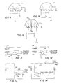
- an electric field is generated therein such that the ions move in accordance with the electric field.
- flux lines are illustrated as intersecting with and/or extending from the electrodes.
- the semicircular line 154 represents the interior surface of the plastic bubble of the ion chamber.
- V s is the sensing voltage and usually designates the collecting electrode; 0 v represents a grounded element; and V s1 , V s2 and V s3 represent different collecting electrodes set at different predetermined voltages.
- electrode E1 is the collecting electrode and is set at voltage +V s . It is to be understood that the voltages illustrated and discussed herein are only exemplary and any discrete voltage levels can be used in place of the described and illustrated voltages. For example, rather than having a positive voltage at the collecting electrode, a negative voltage can be applied thereto. In that case, positive ions are collected at the collecting electrode rather than negative ions as discussed with respect to a +V s at the collecting electrode. Also, the 0 v could be any internal ground voltage other than zero volts which is designated as ground for the IC dosimeter.
- electrode E1 is the collecting electrode and is electrically biased to predetermined level +V s .
- V s implies that this electrode is connected to a sensing circuit.
- the voltages E n imply connection to a voltage source with no measurement of collected charge being done.
- Electrodes E2 and E3 operate as biasing electrodes and are at 0 v.
- the one end of the flux lines of the electric field in Figure 8 intersects collecting electrode E1 and the other end intersects biasing electrodes E2 and E3. Also, since interior surface 154 will be typically grounded and since the plastic is conductive in nature, the electric field does extend to that interior surface.
- the radiation detection subassembly includes means for generating the electric field.
- the strength of the electric field generally depends upon the voltage differential between the collecting electrode and another element within or without the volume of gas. Therefore, the strength of the electric field can be varied by changing the voltage differential, at least in Figure 8, between electrode E1 and electrodes E2 and E3. By applying a lower voltage to electrodes E2 and E3, the electric field within the volume of gas increases. Similarly, by raising the voltage V s on collecting electrode E1, the electric field increases.
- interior surface 154 is grounded at 0 v, electrodes E1 and E2 are biased to voltage +V e and electrode E3 is selected as the collecting electrode and is biased to +V s . Since electrode E3 is selected as the collecting electrode, the region swept is that region between electrode E3 and surface 154 and is limited to the radially outer sectors of the volume. A complex conically cylindrically symmetric region is therefore swept.
- any one of electrodes E1, E2 and E3 can be the collecting electrode since V s1 need not equal V s2 or V s3 .
- the means for generating the electric field need not be a battery. It can be two dissimilar materials which are physically and electrically connected at one end. For example, if the ends of a piece of copper and a piece of steel are joined, a voltage develops across the free ends of the copper and steel due to the work function difference between the different materials. This voltage differential may be sufficient to create the electric field for the IC dosimeter. Particularly, a gold plate or element and a carbon based plastic may be utilized to generate an electric field in this fashion due to the work function between gold and the carbon based plastic. Also, the biasing electrodes do not have to be exposed to the gas (excepting the collecting or sensing electrodes) since a field can be developed by conductors either within the IC or within the hemispheric bubble defining the volume of gas.
- the radiation interacts with the gas in the ion chamber generating ions which move in the electric field.
- the ions of one polarity are collected on the exposed collecting electrode and the charge signal therefrom is amplified. If the collecting electrode is biased to a positive voltage with respect to the other electrodes, negative ions will be attracted and the voltage +V s will decrease based upon the amount of collected ions.
- the number of ions generated is proportional to the dose received. Ideally, all the ions generated are collected.
- the gas in the chambers should be under a slight pressure to provide some crush resistance when thin covers are used for the detection of beta particles.
- the choice of gas is determined by the energy response desired. Air, nitrogen, argon or tissue equivalent gas are possibilities. The use of air would result in the radiation being measured in Roentgens (R). Tissue equivalent gas measures radiation in rad (radiation absorbed dose) or Gy (gray unit which equals 100 rads).
- the ion chamber performance is not ideal.
- the greater the radiation dose rate the greater the number of ions generated.
- the ions are not collected instantly, so the concentration of ions in the gas increases with increasing dose rate. This results in some of the positive ions recombining with negative ions. These ions cancel and are not collected by the electrodes. Thus, the charge collected is decreased by this recombination and the measurement is no longer proportional to the dose received.
- the minimum size of the ion chamber is determined by the minimum dose rate to be reliably detected.
- the dose rate permissible in an unrestricted area is 2 mR/hr.
- a reasonable charge sensitivity for an integrated circuit amplifier is 1000 electrons since engineering literature describes an amplifier that can sense lmv with an input capacity of 1 x 10 ⁇ 14f.
- 1 mR as being the amount of radiation required to generate 2000 ion pairs/mm3
- a volume of 180 mm3 would average one pulse every five seconds at a dose of(2 mR/hr) 0.516 ⁇ C/kg/hr.
- the shape of the ion chamber is controlled by the conflicting desires to have as high an electric field as possible and as low a capacitance as possible.
- the higher the electric field the faster the ions move and higher the dose rate which can be accurately monitored.
- the lower the capacitance the smaller the minimum charge and hence the smaller the dose which can be measured.
- a large area parallel plate arrangement could give the highest field. Concentric spherical surfaces would give a low capacitance. As mentioned above, at high dose rates, recombination occurs.
- the different ion chambers and measurement circuitry can accurately measure different dose rates. It is usually necessary to measure dose at three or more depths into the tissue, so several ion chambers are needed, each with different shielding or energy response. Ideally, the IC dosimeter has two or more chambers at each tissue depth.
- the high dose rate chamber would be significantly smaller and have a higher field than the low dose rate chamber.
- the collecting electrode need not be directly attached to the integrated circuit as illustrated in Figure 3A.
- the added capacitance of connecting wire 114 can be tolerated because ion chamber 98 does not need to be sensitive to miniscule doses.
- the control electronics in the detector control and interface unit 14 monitor the dose rate from each detection subassembly and select the chamber which is most accurate.
- FIG. 8 shows the bias applied when measuring a low dose rate. All charge is collected at center electrode E1. Charge is collected from the total volume.
- Figure 9 shows the bias conditions for which charge is measured in a smaller, high field, volume. In Figure 10, the collecting electrode and hence the volume swept can be selected.
- Figures 11 and 12 illustrate circuits which measure the current to the collecting electrode 155 rather than the charge due to the collection of ions on that electrode.
- one input of amplifier 157 is biased to a voltage level dependent upon the power source V1 and the value of resistor 159. The voltage changes due to the voltage drop across resistor 159 as the collected current is conducted through it.
- electrode 156 is a bias electrode that establishes the electric field in the volume of gas.
- resistor 161 provides a feedback voltage signal that is a basis for comparing the signal obtained from collecting electrode 155.
- FIGS 13 and 14 illustrate flyback circuits to increase the voltage levels and hence increase the electric field.
- the use of flyback circuits permits bias control circuitry for a particular ion chamber to increase the bias field V e(g) (depicted as V e in Figure 9) as the dose rate increases. For example, for every factor of 10 increase in the dose rate, the bias is increased by the square root of 10 to maintain recombination losses at the same level.
- the flyback transformers 160, 160a and 160b are triggered via transistor T g after the dose rate exceeds some rate threshold.
- the charge on capacitor C f is increased due to the release of energy from inductors 160 and 160a when T g is turned off.
- the battery voltage is applied to V e with substantially no voltage loss other than the diode.
- the detector control in Figure 1 can be configured to control the flyback circuits in this manner.
- This power circuitry is part of the detector control as is any required voltage regulation circuitry.
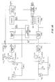
- FIGs 15, 16, 17, 18, 19, 20 and 21 illustrate electrical block diagrams for the dosimeter.
- collecting electrode 170 is electrically biased to predetermined voltage level V s .
- Bias electrode 171 establishes the electric field in the gas and is coupled to power supply 173.
- the dashed box 175 indicates that those components are part of one radiation subassembly in Figure 1.
- the dashed box 177 indicates components considered part of detector control and interface unit 14 in Figure 1.
- the collecting electrode is exposed to the volume of gas.
- the collecting electrode is also the control gate for amplifying transistor T0, i.e., the collecting electrode is "incorporated" into the amplifier embodied by transistor T0.
- the source of amplifying transistor T0 is coupled to voltage V2 and the drain of the amplifying transistor places a signal on line 172 representative of the amount of accumulated charges on the electrode and hence the radiation sensed by the IC dosimeter.
- Buffer amplifier 174 isolates amplifying transistor T0 from the rest of the circuitry and amplifies T0's output.
- V0 is applied to sense amplifier 176.
- Sense amplifier 176 determines when the V0 drops below a predetermined threshold V ref and generates trigger signal for counter 178.
- the trigger signal is also applied as a clearing control signal to a circuit which restores voltage V, to the collecting electrode or clears the accumulated charge from the electrode. If V s is a positive voltage with respect to the voltage on 171, negative ions will be attracted to collecting electrode 170 and voltage V0 will fall dependent upon the accumulated charge. When V0 falls below V ref , sense amplifier 176 triggers counter 178.
- Switching transistor T1 applies a clearing voltage V c1 to the control gate of amplifying transistor T0. Clearing voltage V c1 is developed across capacitor Cl. Switching transistor T1 is turned on by the clear control signal, i.e., the trigger signal, from sense amp 176 and thereafter couples capacitor Cl to the control gate of amplifying transistor T0. During the trigger pulse, inverter 180 turns second switching transistor T2 off and therefore isolates V chg from capacitor Cl. When the trigger signal is removed, second switching transistor T2 is turned on and capacitor Cl is charged by voltage V chg . It is recommended that transistors T1 and T2 do not conduct at the same time. In this sense, the turn off time of the transistors must be quick and the turn on time must be slow.
- transistors T0, T1 and T2 as well as buffer amplifier 174, sense amplifier 176, counter 178 and capacitor Cl are all disposed within the integrated circuit.
- Other data processing components in the detector control and interface unit are downstream of counter 178 and may or may not be on the same IC.
- Collecting electrode 170 is directly exposed to the volume of gas and may be embodied as a sense pad which is placed above a conductive channel running internally into the integrated circuit element. The sense pad may be larger than the internal conductive channel because the sense pad can be spread over a top layer of insulation on the surface of the integrated circuit.
- CMOS technology can be utilized to obtain the low power detector described herein.
- sense amp 176 is part of amplifier 20; counter 178 corresponds to part of calculator and controller 30; transistors T1 and T2 and associated circuitry correspond to charge removal device 26.
- Counter 178 can be reset or re-zeroed on a periodic clock signal from computer 30.
- the device control and interface unit could operate on purely analog signals from the subassemblies rather than digital signals.
- the sense amp is a means for converting the signal from the buffer into a storable signal and the counter accumulates that storable signal as radiation dose data. As is described in detail below, the charge removal, the electric field generation and leakage compensation are all interrelated.
- switching transistor T1 to provide a clearing voltage (V c1 ) to the control gate of amplifying transistor T0 presents a problem regarding the current leakage, ILEAK, from the transistor diffusion to the IC substrate.
- the current leakage is designated by dashed lines as ILEAK in Figure 15 from the integrated circuit substrate to the drain of switching transistor T1.
- This current leakage ILEAK will be sensed as an accumulated charge and hence a dose. A rough calculation indicates that this leakage could cause a pulse every eight seconds. For a 0.18cm3 chamber, this gives a background reading of radiation of 1.25 mR/hr which is unacceptable. The effect of leakage should be less than 1 mR/day. Corrective measures for minimizing the effect of ILEAK are discussed later (1 R equals 0.258 mC/kg).
- Figure 16 illustrates collecting electrode 170 and biasing electrode 182 as well as a rate change circuit that includes transistor T R . Items to the left of the double dashed line 85 are considered part of the detection subassembly; items to the right are part of the detector control.
- the biasing voltage V e is applied to biasing electrode 162 providing an electric field that extends between collecting electrode 170 and biasing electrode 182.
- the bias voltage can be controllably set by a control circuit 184 coupled to the output of counter 178.
- biasing voltage V e can be controllably set at a plurality of discrete levels dependent upon the count in counter 178.
- the flyback circuits of Figures 13 and 14 could be used to apply this increased biasing voltage.
- Transistor T r is controlled by rate change control signal TR gate from control circuit 184.
- rate change control signal TR gate is high, capacitor C r is electrically coupled to the control gate of transistor T0. Therefore, accumulated charge on collecting electrode 170 must charge or discharge capacitor C r and hence the rate at which signal V0 changes is decreased because of the added capacitance.
- the electronics has a maximum count rate set by its speed. If this maximum count rate becomes a limitation rather than the charge recombination rate discussed earlier, it is necessary to add the extra capacitance C r to reduce the sensitivity of the detection subassembly.
- C r When transistor T r is conductive, the amount of charge required to trigger sense amp 176 is increased.
- the control circuit 184 would monitor the dose rate and provide rate change control signal TR gate when the dose rate exceeds a predetermined level.
- the major difficulty with clearing or restoring voltage V s to the control gate of transistor T0 via transistor T1 is the current leakage ILEAK from the integrated circuit substrate to the drain of transistor T1 and hence the collecting electrode.
- the rough estimate earlier presented indicates that this leakage may cause a pulse every eight seconds.
- One method of compensating for ILEAK is simply to have the dosimeter not register any pulses unless the pulses are less than eight seconds apart. This operation is simply pulse stream manipulation.
- a second simple method is to have the dosimeter not register any dose when it is disabled or turned-off. The dosimeter could be stored in a charging/disabling cradle that time.
- Figure 17 illustrates a block diagram circuit for analog current subtraction used to compensate for the leakage current.
- Current generator ICOMP is controlled by ICOMP control 186.
- the ICOMP control would be sent during calibration of the dosimeter.
- ILEAK would be a current source and ICOMP would be current sink.
- ICOMP is controllable by ICOMP control 186.
- the difficulty with this system is having ICOMP vary in a similar fashion to ILEAK as conditions vary.
- FIG 18 illustrates another alternative embodiment of a circuit to compensate for ILEAK.
- the sensing circuit is indicated by character “a” such that transistor T0 is now T 0a .
- T 0a is coupled to buffer amplifier 174a, sense amp 176a and counter 178a.
- a duplicate circuit is illustrated with character “b.” Therefore, the counterpart to transistor T 0a is T 0b , buffer amp 174a is duplicated as amp 174b, etc.
- the primary distinction between the duplicate circuit and the sensing circuit is that the control gate for transistor T 0b is not coupled to the collecting electrode in the duplicate circuit.
- T 1a and T 1b are equal in size and do not contain any gross defects
- the leakages ILEAKA and ILEAKB should be almost identical. In other words, both leakage currents should track each other as conditions vary. Therefore, the true dose exposure can be determined by taking the difference between the number of pulses received by circuits a and b.
- One compensation method utilizes a rate compensator 188. It senses when the pulse rate in sense amp 176a is less than the pulse rate in sense amp 176b and prevents an incrementing counter 178a. Thus, no dose is registered unless it is in excess of ILEAKB.
- a second method is better adapted to proportional but unequal ILEAKA and ILEAKB.
- a prescaler 190 decrements counter 178a when the count value from duplicative counter 178b equals the compensation count value in leakage compensation memory 192.
- the scaling circuit compensates for the measurement circuits not being identical.
- the leakage compensation memory is loaded during calibration and contains the proportionality constant related to the two circuits leakages.
- Figure 19 illustrates a further circuit, in block diagram form, for eliminating switching transistor T1 and thus the source of the leakage.
- the collecting electrode is only connected to the control gate of transistor T0.
- the bias V e(t) drives a charge of one polarity to the collecting electrode 170.
- the single polarity charge accumulates ions at collecting electrode 170 until sense amplifier 176 triggers counter 178.
- Control circuit 184 changes the bias signal applied to bias electrode 182 thereby switching the electric field in the volume of gas to bring ions of the opposite polarity to collecting electrode 170.
- the oppositely charged ions cancel the previously accumulated charge on collecting electrode 170.
- the minimum voltage V e (t) min is less than V s which in turn is less than the maximum voltage V e (t) max .
- the reference voltage V ref (t) is varied such that the sense amp triggers the counter when signal V0 exceeds a maximum threshold level in one instance and falls below a minimum threshold level in a second instance. Therefore, either the reference voltage must be switched within sense amp 176 or electrical circuitry be designed to determine when V0 passes beyond a predetermined window.
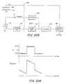
- FIG 20A illustrates a block diagram circuit which changes the voltage of collecting electrode 170 via a coupling capacitor C0.
- control circuit 194 switches coupling voltage V coup1 (t) to a different predetermined level. Therefore, the voltage V s is biased to a high and then a low predetermined level based upon a level control signal applied to level control circuit 194.
- the biasing voltage V e applied to biasing electrode 182 is at an intermediate level as compared to the maximum coupling voltage V coup1 (t) max and the minimum coupling voltage V coup1 (t) min . Switching via the coupling capacitors is advantageous because all ion chambers can have the same counter electrode potential (Ve) and the coupling capacitor is part of the integrated circuit.
- the sense amp must now sense two voltages so some type of Schmitt trigger, window comparator, or dual sense amplifiers must be utilized as sense amp 176.
- the reference voltage V ref (t) varies between two threshold levels dependent upon the coupling voltage.
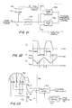
- Figure 21 shows a block diagram of another circuit for clearing the accumulated charge on the collecting electrode.
- Figure 22 shows the timing diagram for the operation of the circuit in Figure 21.
- the polarity of the electric field is reversed periodically (see V z in Figure 22) similar to the operation described in Figure 19, i.e., when V D reaches V revL or V revH or effectively after a certain number of counts.
- Sense amplifiers 176a and 176b trigger a counter or other detector control component when the signal exceeds or falls below one of two reference voltages V ref1 or V ref2 .
- the threshold for sensing each accumulated charge is low if each time the threshold is exceeded, the voltage V D is changed in a stepwise manner.
- the relatively small voltage step restores the voltage of the amplifier input to its original value (see V c between times t1 and t2) and prepares the amplifier to sense another pulse.
- This circuit substantially eliminates any inaccuracy which arises when the field polarity is changed after each pulse. It also confers some noise resistance similar to that given by constant charge removal versus constant voltage reset.
- a change in V D indicates one pulse sensed by one of the sense amps. From times t1 to t2, these pulses represent charge sensed and thus dose received. From times t2 to t3, the pulses are simply a result of the changing V z being capacitively coupled to V c .
- guard ring as one of the electrodes (for example, E3) around the sensing pad (for example, E1 or E2) to minimize leakage over the silicon dioxide layer in the integrated circuit and the passivation materials on that integrated circuit.
- One method of compensating for stray capacitance and stray electric fields developed by components internal of the integrated circuit is to have the guard electrode at the same potential as the sensing electrode. The geometry of the guard and the sensing electrode would be chosen such that the guard receives few of the flux lines of the electric field but surrounds the sensing electrode, thereby interrupting any surface leakage from the internal components.
- a large ion chamber utilizes an integrated circuit control without switching transistor T1 and utilize electric field reversal in order to detect lower levels of radiation. Then, the same or a different integrated circuit senses the accumulated charge from a second smaller ion chamber utilizing the simplest sensing circuit illustrated in Figure 15. No leakage compensation is necessary in this simple circuit because the count from the small ion chamber is recognized only if the dose rate is high. Also, this ion chamber configuration would be repeated for each of the three tissue depths at which a measurement is to be made.
- Figure 23 is a further development from Figure 10.
- selector control 196 actuates selecting means 200 which selects one of the electrodes E1, E2 or E3 as the collecting electrode.
- the accumulated charge from the selected collecting electrode is applied via T s1 , T s2 or T s3 to buffer amplifier 174.
- biasing electrodes are set at discrete biasing voltage levels to produce distinct electric field configurations at various times. Because different volumes of the gas are swept by the electric field from the electrodes, setting the biases and switching the collecting electrode changes the sensitivity and dose rate limits of the dosimeter.
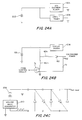
- Figures 24a, 24b and 24c illustrate power circuits for the dosimeter.
- the power from battery 202 is applied directly to ion chamber power 204 as well as to circuit power 206.
- Figure 24c illustrates a capacitive voltage multiplier which increases battery voltage without the need for an inductor.
- Square wave generator 210 activates the set of capacitors to achieve this multiplication of voltage.
- Figure 25 illustrates, in block diagram form, the memory and communications section in the detector control.
- this section is associated with one IC.
- This communications section is a means for recovering or for transferring the radiation count (radiation dose) from the counters.
- the dashed line 212 indicates an interface with a bus structure for transferring data and command or control signals between the memory and communications sections for other ICs.
- all the integrated circuits are connected as is best illustrated in Figure 26, the power and communication path diagram.
- the alarm out line is activated if any one of the ICs, IC1, IC2 or IC3, generates an alarm.
- the alarm is passed from IC to IC by the alarm-in/alarm-out interconnection between the three integrated circuits.
- the alarm is ultimately passed to the human interface 34 in Figure 1.
- the data out line is coupled to the electronic interface 36 when the dosimeter is configured as a wearable display personal dosimeter.
- the chip enable command is periodically actuated to provide a seemingly continuous radiation readout or is generated by actuation of a control button on the display dosimeter.
- the alarm-out line is raised when any line coupled to OR gate 214 is raised: the alarm-in line, the dose alarm/rate alarm line from the control circuit/radiation count counters or the cyclic redundant character (CRC) control check circuit 216.
- CRC cyclic redundant character
- Memories M1, M2, M3, M4, M5, M6, M n-3 , M n-2 , M n-1 and M n are coupled to various counters and other devices in the integrated circuit.
- counter 178 (Fig. 15 and others) may be directly coupled to one of these memory units or may be the memory unit M n .
- Counter 178 and control circuit 184 must include some type of memory to trigger the control signal g (see Fig. 14), the change rate signal TR gate (see Fig. 16), the ICOMP control (see Fig. 17) and the level and pulse duration of V e(t) (see Fig. 19) and the coupling voltage (see Fig. 20).
- the leakage compensation memory is a memory unit.
- Shift registers S1, S2, S3, S4, S5, S6, S n-3 , S n-2 , S n-1 and S n are connected to corresponding memory units. These serially connected shift registers are supplied with data on the data-in line.
- the CRC space control device 218 is needed to hold the 16 CRC characters used to confirm accurate data reception without displacing any data from its proper locations. All of the serially connected registers are loaded during a data write routine and a shift register write (SRW) control signal from counter 220 loads the shift register data into the appropriate memory. Shift control to each shift register is also accomplished by a control line from counter 220.
- SRW shift register write
- Counter 220 is activated by a chip enable signal and a clock signal which is fed to AND gate 222. The output of the counter is also fed to CRC calculator 224 to indicate when to calculate and output, or check, the CRC.
- the control input/output circuit 226 is coupled to the chip enable line and to the output of the CRC checker circuit 216. I/O control 226 activates transistor T out and allows the data to be reflected on the data-out line. Also, when the counter 220 determines that the last 16-bit word is appropriately checked, it places a value of the CRC calculator 224 on the data-out line. The last 16 bits represent the CRC code which is used by the receiving device to determine if the transmission was accurately received.
- Data can be shifted into memory with a shift register read/write control line. When the read or write operation is completed for the present chip, the next chip is enabled. To write data from outside, data is shifted from M x to S x by the shift register read/write control line. Then the shift registers are shifted once on each clock cycle with one bit coming out and also going to the CRC calculator 224. When all the data is out, the 16-bit CRC is shifted out.
- Figure 26 illustrates the power and communication path for the dosimeter with multiple integrated circuits IC1, IC2 and IC3. Power and ground are applied from an internal battery in the dosimeter control unit.
- the alarm is a daisy chained signal. If the alarm is active, it gets passed along. The active alarm signal out of the last chip turns the piezoelectric buzzer on if the dosimeter is configured with an active human interface.
- the alarm could trigger a communications transmit command through the electronics interface. Upon receipt of this transmit command, the dosimeter would transmit radiation data, e.g., dose or dose rate, to an external device. Data read and write is synchronized by the clock.
- the clock and all power for the external communication drivers and internal shift register is provided by communications power which is in turn supplied by a calibration and display unit or a display cradle unit.
- communications power which is in turn supplied by a calibration and display unit or a display cradle unit.
- the simplest dosimeter embodiment utilizes an internal battery which is chargeable.
- a low battery voltage warning circuit audibly warns or alarms the user of a low battery.
- the chip enable and read line are held low.
- the read/write is brought high for X clock cycles and then low. After Y cycles, the chip enable is brought high. Z cycles later, all data in the IC1 is shifted serially out the data-out line. When IC1 is done, it enables IC2. Z cycles later, the data from IC2 comes out on the data-out line.
- the dosimeter counters are disabled.
- the read/write control line is held high and kept high. After A cycles, the chip enable is brought high. After B cycles, the data is serially read in on the data-in line until all shift registers are full. When IC1 is loaded, it raises the chip enable of IC2. When all the data is loaded, bringing the write line low before lowering the chip enable line causes data to be stored into the integrated circuit chip memories.
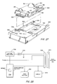
- Figure 27 illustrates dosimeter unit 310 having ion chambers 312, 314 and 317.
- the large ion chamber 312 is most sensitive to radiation.
- the smaller chambers 314 and 317 are less sensitive but are capable of accurately detecting higher doses and dose rates as compared with the larger chamber.
- the ion chambers inside domes 312, 314 and 317 may all be identical and so have identical dose rate responses, but have different wall thicknesses and, thus, be measuring dose at different depths into the body.
- Dosimeter unit 310 includes slot 316 for a film badge and aperture 318 which allows radiation to impinge directly upon the film placed in slot 316 after passing through various materials and material thicknesses.
- Electrical contacts 320 extend from one end of dosimeter unit 310.
- External connections 320 on dosimeter unit 310 are provided to facilitate the transfer of information, i.e., radiation data, control commands, ground and power signals as necessary.
- the use of output drivers in the dosimeter unit that obtain power from an external battery in a cradle display unit 322 prevents the possibility that one or more contacts 320 would short together and result in a spark or drain of the internal battery in the dosimeter unit.
- the only common connection between the internal circuitry in the dosimeter unit and the external unit such as display unit 322 is ground.
- data communications can use an optical link, encoded sound, near or far field electromagnetic waves, rather than electrical contacts.
- a cradle display unit 322 is separably mated with dosimeter unit 310. As illustrated, display unit 322 includes lip portions 324 which mate with ledge or flange 326 on dosimeter unit 310. Display unit 322 includes LCD display 328 and recessed control buttons 330. A clip 332 is disposed on the back of the display unit 322 to facilitate the wearability of the entire device. Electrical contacts 320 on dosimeter unit 310 mate with complementary electrical contacts not shown in display unit 322. The dosimeter unit is separably mated to display unit 322 in order to allow the dosimeter unit to be regularly tested and appropriately calibrated.
- the display unit and dosimeter unit can be permanently mated in order to provide a substantially continuous or controllably displayable radiation data display.
- the geometric configuration of ion chambers 312, 314 and 317 is only exemplary.
- the ion chambers can be geometrically configured in as many shapes as are permitted by manufacturing constraints.
- Display 328 is a means for recovering the radiation count from the counters.
- Display unit 322 can also be configured as a programming device to set threshold limits, e.g., dose and dose rate thresholds, in the dosimeter unit.
- Control buttons 330 can be utilized to confirm the thresholds input via the buttons and then confirm a successful programming of the dosimeter unit. Since unit 322 can be viewed as a programming device, that unit is referred to herein as a programming and display unit.
- FIG. 28 illustrates, in block diagram form, the electrical components of programming and display unit 322.
- Battery 334 is coupled to voltage regulator 336 which supplies voltage V supply to microcomputer on a chip 338 (herein microcomputer chip 338) and to connector pin unit 340.
- Connector pin unit 340 matingly couples with pin unit 320 of the dosimeter unit 310.
- Microcomputer chip 338 is coupled to input buttons 342 and display device 344. Microcomputer chip 338, when activated by input buttons 342, generates a data transfer command to dosimeter unit 310. To display the radiation dose, a dose transfer command is generated and applied to the dosimeter unit. Similarly, a dose rate transfer command is used to obtain the dose rate data. This transfer command is the read command discussed above with respect to Figures 25 and 26. The output from the dosimeter unit is placed in a memory which is part of microcomputer chip 338. Also, the radiation data from the detector control interface, e.g., the counters, is displayed on display 344. Microcomputer chip 338 also programs threshold values into dosimeter unit 310. For example, microcomputer chip 338 programmably sets the total dose alarm threshold, the dose rate threshold and the trigger threshold for the counter. The total dose alarm threshold is that radiation dose value which, when exceeded, triggers the audible and electrical alarm in the IC dosimeter.
- Figure 29 illustrates a calibration and display device 350.
- the dosimeter unit is placed in either of two mounting positions, the calibration position 352 or the readout position 354.
- Calibration unit 350 includes display device 356 and keyboard 358.
- Printer 360 provides a printed copy of the information obtained from the IC dosimeter. Particularly, during calibration, a predetermined amount of radiation, from radiation source 357 (shielded by shield 359), is directed toward the dosimeter unit.
- Calibration unit 350 monitors the resulting radiation data (both total dose and dose rate as necessary) and then compares that radiation data against accurately predetermined radiation data. This computation is carried out in microcomputer 362. The dosimeter would then be programmed such that the threshold level of the sensing amplifier (a threshold determining means) would be set and further the alarm threshold levels for the alarm circuitry would be set by calibration unit 350.
- calibration unit 350 When the dosimeter unit is in readout position 354, calibration unit 350 would generate a transfer data command to the dosimeter and read out all data including the current radiation data from the memory units. Appropriate information is displayed on display 356 and printed out by printer 360. Additionally, calibration unit 350 could program (record) a date of calibration into the memory of the dosimeter unit as a historical indicator. The calibration unit also resets or clears selected counters, if necessary, in the dosimeter. Additionally, the calibrator includes a memory, clock, analog and digital interface circuits, and an I/O computer communications port to transfer data information to other computer devices.
- Figure 30 illustrates a wide area radiation monitor system which utilizes a plurality of dosimeters DOS1, DOS2, DOS3 and DOS4 dispersed in a random fashion throughout the area sought to be monitored.
- the dosimeters communicate with area monitor 366 either when the dose or dose rate alarm threshold is exceeded or as periodically commanded by the monitor control.
- a multiple IC dosimeter control 368 periodically obtains the radiation data from IC dosimeters DOS1, DOS2, DOS3 and DOS4 by issuing appropriate transfer commands; accumulates the data and relates the data to the particular dosimeter by way of identification data uniquely associated with each dosimeter, and relates the data to date and time information; and during other occasions periodically communicates via communications circuit 372 to an external command unit.
- Area monitor 366 would include its own power source 374.
- the area monitor system can also be configured to determine the direction and location from the monitor control of the dosimeter sounding the alarm, i.e., detecting an overexposure of radiation.
- One method of determining direction and location is triangulation using a plurality of monitor controllers and a central controller. Also, users can be warned if they are approaching a high radiation area.
- the IC dosimeter may include some components to eliminate the possibility of data loss.
- An EEPROM on the integrated circuit could be utilized such that battery failure does not result in a loss of data. Further, the dosimeter could chirp a "low battery" signal when the internal battery reached a predetermined low value. Since the alarm function in the dosimeter uses a substantial amount of power, two batteries or power sources can be used. When the alarm battery is low, the alarm is disabled, the detector control and interface battery enables the detection subassemblies to continue to detect radiation exposure notwithstanding the disabled alarm. A single battery and appropriate circuitry can be used in conjunction with an alarm battery level disable circuit to also achieve this function. Alternatively, the detection control power source may be solar cells.
- the human interface alarm sounded by the detector, could include a visual alarm as well as an audible alarm.
- the alarm signifying an overexposure of radiation could be different than the alarm signifying an unacceptably high dose rate, i.e., different intensity, frequency, and/or duty cycle.
- transistor T0 may be part of a differential amplifier or the collecting electrode may be a voltage follower input.
- Transistors T1 and T2 may be two of many additional transistors.
- the audible alarm could require a square wave generator as illustrated in Figure 24c.
- the dosimeter can be made to fit in a band or worn like a watch, glove or ring.
Landscapes
- Physics & Mathematics (AREA)
- Health & Medical Sciences (AREA)
- Life Sciences & Earth Sciences (AREA)
- General Physics & Mathematics (AREA)
- High Energy & Nuclear Physics (AREA)
- Molecular Biology (AREA)
- Spectroscopy & Molecular Physics (AREA)
- Measurement Of Radiation (AREA)
- Investigating Or Analyzing Materials By The Use Of Fluid Adsorption Or Reactions (AREA)
Claims (23)
- Dosimètre électrique pour enregistrer et afficher des données de radiation, lors de la réception d'une somme de radiation et lors de contrôles du taux de radiation, comprenant :a. une unité de détection de radiation (310) incluantb. au moins un sous-ensemble de détection de radiation (1, 2, n) avecc. des moyens (136 ; 312, 314, 317) pour définir un volume de gaz adapté pour être ionisé par irradiation,d. un module de circuit intégré (130),e. des moyens (E₁, E₂, E₃) pour générer un champ électrique avec des lignes de flux,f. des moyens d'amplification (20, T₀, 174) étant sensibles à l'ionisation du volume de gaz par la radiation, pour développer un signal représentatif de la radiation,g. une unité d'affichage commandable (24 ; 328 ; 356),h. des moyens d'interface (212) pour mesurer la somme et le taux de radiation à partir du signal des moyens amplificateurs (20, T₀, 174) et pour mémoriser la somme et le taux de radiation en tant que données d'irradiation,i. des moyens (Tout, 320, 340) pour transférer la somme et le taux de radiation à partir des moyens d'interface (212) jusqu'au moyen d'affichage (328) lors de la réception d'une commande de transfert de la somme et du taux de radiation.j. des moyens pour une génération contrôlable des commandes de transfert de la somme et du taux de radiation et pour transmettre les commandes de transfert aux moyens de transfert,caractérisé en ce qu'il comporte en outre :k. une portion de surface conductrice (128) sur le module de circuit intégré en contact direct avec le gaz pour y collecter les ions,l. les lignes de flux des moyens (E₁, E₂, E₃) pour générer un champ électrique intersectant la portion de surface (128) et s'étendant à travers le volume de gaz de sorte que les ions se déplacent en suivant le champ électrique, etm. les moyens d'amplification (20, To, 174) incorporent la portion de surface et sont disposés dans le module de circuit intégré (130).
- Dosimètre selon la revendication 1, caractérisé en ce que l'unité d'affichage contrôlable (328) est montée de manière amovible (322, 324) avec l'unité de détection de radiation (310).
- Dosimètre selon la revendication 1, caractérisé en ce que l'unité d'affichage contrôlable (356) est comprise dans une unité d'affichage et de calibrage (350), laquelle est montée de manière amovible avec l'unité de détection de radiation (310).
- Dosimètre selon la revendication 3, caractérisé en ce que les moyens d'interface (212) pour le mesurage calculent et mémorisent des sommes et des taux de radiation totale comme des données de radiation, l'unité de calibrage (350) comporte une source de radiation (357) ayant un niveau prédéterminé de radiation, et des moyens pour comparer les sommes et taux de radiation totale des moyens d'interface (212) avec les valeurs prédéterminées, et pour fournir une indication sur leur différence.
- Dosimètre selon la revendication 3 ou 4, caractérisé en ce que l'unité de calibrage (350) comporte des moyens d'horloge et de calendrier et une mémoire, tous les deux étant connectés à un contrôleur, et les moyens d'interface comportant un composant de mémorisation de donnée, le contrôleur lisant et enregistrant une durée, une date et des données de radiation dans la mémoire à la demande, et mémorisant la durée et la date de calibrage dans le composant de mémorisation de donnée.
- Dosimètre selon l'une quelconque des revendications 1 à 5, caractérisé, en ce que les moyens d'interface (212) sont des moyens d'interface contrôlables pour la mise en forme et pour tamponner des signaux en provenance des moyens d'amplification (20, T₀, 174).
- Dosimètre selon l'une quelconque des revendications 1 à 6, caractérisé en ce que les moyens d'interface (36, 312) comportent des moyens pour transformer (176) le signal en donnée de radiation mémorisable et pour accumuler les données mémorisables, les données de radiation accumulée constituant les données de radiation.
- Dosimètre selon la revendication 7, caractérisé en ce que l'électrode de collecte (170) est polarisée électriquement par les moyens (Vs) de génération du champ électrique et la polarisation change à cause des ions collectés, le sous-ensemble de détection de radiation (1...n) comporte des moyens (184, T₁, T₂, TR) pour restaurer la polarisation de l'électrode de collecte.
- Dosimètre selon la revendication 8, caractérisé en ce que les moyens de restauration sont commandés par des moyens de commande de détection (184) qui font partie des moyens d'interface (212), les moyens de contrôle de détection contrôlant la polarisation dépendante du signal.
- Dosimètre selon la revendication 8, comportant un module de polarisation (171) faisant partie à la fois des moyens de définition du volume de gaz et des moyens (Vs) de génération du champ électrique , les lignes de flux du champ électrique intersectant l'électrode de collecte (170) et le module de polarisation (171), et les moyens de contrôle de détection (184) positionnant une polarisation correspondante dans le module de polarisation.
- Dosimètre selon la revendication 10, caractérisé en ce que les moyens de commande de détection (184) positionnent la polarisation et la polarisation correspondante à une pluralité de niveaux de tension discrets, les niveaux de tension les plus hauts étant postionnés pour les niveaux de radiation détectés les plus hauts tels que représentés par le signal.
- Dosimètre selon la revendication 10, caractérisé en ce que les moyens de commande de détection (184) comportent des moyens (176) pour déterminer si le signal excède un premier seuil dans un premier cas et si il descend en-dessous d'un second seuil dans un autre cas, et en ce que les moyens de commande de détection (184) positionnent la polarisation à un niveau prédéterminé haut et à un niveau prédéterminé bas, et commandent la polarisation correspondante à l'inverse des niveaux haut et bas, en fonction des moyens (176) de détermination.
- Dosimètre selon la revendication 9, caractérisé en ce que l'électrode de collecte (170) est une électrode de détection exposée au volume de gaz et constitue une grille de commande d'un transistor d'amplification (174), le transistor d'amplification faisant partie des moyens d'amplification (20).
- Dosimètre selon la revendication 13, caractérisé en ce que les moyens (184) de repositionnement comportent un transistor interrupteur (T1) interposé entre la grille de commande (T0) et une alimentation de tension de vidage (Vc1) alimentant la polarisation, les moyens de commande de détection (184) générant un signal de commande de vidage qui commande le transistor interrupteur (T1) et la mise en route de la polarisation.
- Dosimètre selon la revendication 14, caractérisé en ce qu'il comporte des moyens (186) pour compenser la fuite de courant par le transistor interrupteur (T1) à la grille de commande (T0).
- Dosimètre selon la revendication 9, caractérisé en ce que le signal de transfert est l'une des deux commandes de transfert de la somme et du taux de radiation, les moyens d'interface (212) comportent des moyens de contrôle de taux de radiation (218, 220, 226) pour recevoir ce signal et pour calculer et mémoriser des données de taux de radiation, des moyens d'interface humains (34) associés, et des moyens pour transférer (226) les données accumulées de la somme et du taux de radiation, respectivement, lors de la réception d'une commande de transfert de la somme et du taux de radiation.
- Dosimètre selon la revendication 9, comportant des premier et second sous-ensembles de détection de radiation (1,2), tous deux faisant partie d'un ensemble de détection de radiation (310), caractérisé en ce que:- un premier volume de gaz (1,2) est plus grand qu'un second volume de gaz (314) des respectifs premier et second sous-ensembles;- des premier et second signaux représentatifs des respectifs premier et second sous-ensembles (1,2) sont appliqués au moyen d'interface (212) via premier et second moyens de couplage;
et en ce que:- les moyens d'interface (212) sont couplés à l'unité de détection de radiation (310) via les premier et second moyens de couplage, et comportent,- des moyens de contrôle de la somme de radiation (30) pour recevoir et convertir les premier et second signaux représentatifs dans un format unique de mesure de radiation. - Dosimètre selon la revendication 17, caractérisé en ce que les moyens de contrôle de somme de radiation (30) comportent des moyens pour sélectionner l'un des signaux convertis en fonction d'au moins un des premier et second signaux, et les moyens d'interface (212) comportent des moyens de mémorisation (M) pour mémoriser le signal converti choisi.
- Dosimètre selon la revendication 18, caractérisé en ce que les moyens (178) de conversion et d'accumulation font partie des moyens de contrôle de la somme de radiation (30) et comportent des moyens (178, 188) pour calculer la somme et le taux de la radiation, les moyens d'interface (212) comportent des moyens (214, 178, 184) pour générer un signal d'alarme lorsque la somme ou le taux de radiation excède un seuil d'alarme programmable.
- Dosimètre selon la revendication 19, caractérisé en ce que les moyens d'interface (212) comportent des moyens d'alarme (214) pour recevoir le signal d'alarme et pour générer au moins un type d'alarme choisi dans le groupe des alarmes visuelles, auditives, électriques, tactiles et olfactives.
- Dosimètre selon la revendication 20, caractérisé en ce que les moyens d'alarme produisent une pluralité de signaux d'alarme de différentes intensités et cadencements en fonction du niveau de la somme ou du taux de radiation.
- Dosimètre selon la revendication 9, caractérisé en ce que le gaz est un gaz équivalent au tissu.
- Dosimètre selon la revendication 9, caractérisé en ce que les moyens (136, 138) de définition du volume de gaz sont constitués d'un matériau équivalent au tissu.
Priority Applications (1)
| Application Number | Priority Date | Filing Date | Title |
|---|---|---|---|
| AT87118192T ATE88577T1 (de) | 1987-01-27 | 1987-12-08 | Gasionisationsdosimeter mit integriertem schaltkreis fuer personen. |
Applications Claiming Priority (2)
| Application Number | Priority Date | Filing Date | Title |
|---|---|---|---|
| US7196 | 1987-01-27 | ||
| US07/007,196 US4769547A (en) | 1987-01-27 | 1987-01-27 | Personal dosimeter having a volume of gas atop an integrated circuit |
Publications (2)
| Publication Number | Publication Date |
|---|---|
| EP0280779A1 EP0280779A1 (fr) | 1988-09-07 |
| EP0280779B1 true EP0280779B1 (fr) | 1993-04-21 |
Family
ID=21724757
Family Applications (1)
| Application Number | Title | Priority Date | Filing Date |
|---|---|---|---|
| EP87118192A Expired - Lifetime EP0280779B1 (fr) | 1987-01-27 | 1987-12-08 | Dosimètre personnel avec chambre d'ionisation sur support de circuit intégré |
Country Status (6)
| Country | Link |
|---|---|
| US (1) | US4769547A (fr) |
| EP (1) | EP0280779B1 (fr) |
| JP (1) | JPS6463887A (fr) |
| AT (1) | ATE88577T1 (fr) |
| CA (1) | CA1276044C (fr) |
| DE (1) | DE3785577T2 (fr) |
Families Citing this family (30)
| Publication number | Priority date | Publication date | Assignee | Title |
|---|---|---|---|---|
| US4970391A (en) * | 1987-01-27 | 1990-11-13 | Medrad, Inc. | Radiation detector with an ionizable gas atop an integrated circuit |
| GB8914910D0 (en) * | 1989-06-29 | 1989-08-23 | Vg Instr Group | Charge transducer |
| US5239085A (en) * | 1991-03-06 | 1993-08-24 | Dow Corning Toray Silicone Co., Ltd. | Organocyclosiloxane and method for its preparation |
| GB9109140D0 (en) * | 1991-04-27 | 1991-06-26 | Siemens Plessey Controls Ltd | Improvements in or relating to personal radiation dose indicators |
| FI934784A0 (fi) * | 1993-10-28 | 1993-10-28 | Rados Technology Oy | Straolningsdetektor |
| US5500534A (en) * | 1994-03-31 | 1996-03-19 | Iowa State University Research Foundation | Integrated energy-sensitive and position-sensitive x-ray detection system |
| FR2753278B1 (fr) * | 1996-09-11 | 1998-10-09 | Commissariat Energie Atomique | Dosimetre x-gamma sensible aux basses energies |
| AT500303A1 (de) * | 1997-04-08 | 2005-11-15 | Kugler Werner Dipl Ing | Dosimetervorrichtung |
| US6402689B1 (en) * | 1998-09-30 | 2002-06-11 | Sicel Technologies, Inc. | Methods, systems, and associated implantable devices for dynamic monitoring of physiological and biological properties of tumors |
| WO2000028337A2 (fr) | 1998-11-06 | 2000-05-18 | Onguard Systems, Inc. | Circuit electronique |
| US6414318B1 (en) | 1998-11-06 | 2002-07-02 | Bridge Semiconductor Corporation | Electronic circuit |
| US6388259B1 (en) | 2000-06-08 | 2002-05-14 | The Boeing Company | Radiation detection method and apparatus |
| JP3981328B2 (ja) | 2000-11-09 | 2007-09-26 | サイセル・テクノロジーズ,インコーポレイテッド | 蛍光タグを使用した生体分子濃縮物をインビボで検出するための方法、回路、および物質の組成物 |
| US7011814B2 (en) | 2001-04-23 | 2006-03-14 | Sicel Technologies, Inc. | Systems, methods and devices for in vivo monitoring of a localized response via a radiolabeled analyte in a subject |
| US7557353B2 (en) | 2001-11-30 | 2009-07-07 | Sicel Technologies, Inc. | Single-use external dosimeters for use in radiation therapies |
| WO2004075032A2 (fr) | 2003-02-19 | 2004-09-02 | Sicel Technologies Inc. | Detecteurs de fluorescence in vivo, systeme et procedes connexes operant conjointement avec des analytes fluorescents |
| JP2004286548A (ja) * | 2003-03-20 | 2004-10-14 | Matsushita Electric Ind Co Ltd | 放射線測定装置 |
| SE0600056L (sv) * | 2006-01-13 | 2007-07-14 | Tomas Unfors | Arrangemang och anordning för avkänning och presentation av strålning |
| JP4548732B2 (ja) * | 2006-02-15 | 2010-09-22 | 富士電機システムズ株式会社 | 中性子検出器および中性子線量計 |
| DE112008002883T8 (de) * | 2007-11-15 | 2011-07-14 | John T.W. ONTARIO Yeow | Kohlenstoffmaterial-Dosimeter |
| DE102013011077A1 (de) | 2013-07-03 | 2015-01-08 | Peter Koller | Detektorplatte zur Strahlungsanalyse und Herstellungsverfahren derselben |
| EP2878976A1 (fr) * | 2013-11-30 | 2015-06-03 | Ion Beam Applications S.A. | Dispositif et procédé de dosimétrie par rayonnements basée sur une chambre d'ionisation. |
| US20160097868A1 (en) * | 2014-10-02 | 2016-04-07 | Source Production & Equipment Co., Inc. | Radiation surveying |
| JP6308934B2 (ja) * | 2014-12-15 | 2018-04-11 | 三菱電機株式会社 | 放射線測定装置 |
| JP2016170179A (ja) * | 2016-06-28 | 2016-09-23 | 和浩 山本 | ハイブリッド線量計 |
| GB201712293D0 (en) * | 2017-07-31 | 2017-09-13 | Kromek Ltd | Charging device |
| JP2018066749A (ja) * | 2017-12-11 | 2018-04-26 | 和浩 山本 | ハイブリッド線量計 |
| JP2019197045A (ja) * | 2019-04-09 | 2019-11-14 | 和浩 山本 | ハイブリッド線量計 |
| US11140476B1 (en) | 2020-06-10 | 2021-10-05 | The Government of the United States of America, as represented by the Secretary of Homeland Security | Remote audible alarm accessory for detection instruments with audio outputs |
| JP2021073472A (ja) * | 2021-02-11 | 2021-05-13 | 和浩 山本 | ハイブリッド線量計 |
Family Cites Families (10)
| Publication number | Priority date | Publication date | Assignee | Title |
|---|---|---|---|---|
| US3878496A (en) * | 1971-06-14 | 1975-04-15 | Us Energy | Selectable level alarming personal dosimeter |
| RO63928A2 (fr) * | 1976-07-20 | 1980-03-15 | Institutul National Pentru Creatie Stiintifica Si Tehnica,Ro | Conteiner a grande capacite pour le transport pneumatique |
| DD155021A1 (de) * | 1980-12-03 | 1982-05-05 | Dieter Schuetze | Schaltungsanordnung zur gleichzeitigen messung der dosis und dosisleistung |
| US4490614A (en) * | 1982-04-30 | 1984-12-25 | Interad Systems, Inc. | Housing for an ionization detector array in a tomographic scanner |
| SU1150595A1 (en) * | 1983-09-14 | 1985-04-15 | Obedinennyj I Yadernykh I | Method of detecting short-life isotopes |
| JPS60108783A (ja) * | 1983-11-18 | 1985-06-14 | Fuji Electric Co Ltd | 放射線モニタシステム |
| GB2158572A (en) * | 1984-05-09 | 1985-11-13 | Quantor Corp | Detecting low level radiation sources |
| JPS6148784A (ja) * | 1984-08-16 | 1986-03-10 | Yutaka Murata | 放射能測定装置 |
| JPS6161080A (ja) * | 1984-08-31 | 1986-03-28 | Toshiba Corp | 放射線モニタ装置 |
| US4680471A (en) * | 1985-03-20 | 1987-07-14 | Motorola, Inc. | Integrated circuit packaging |
-
1987
- 1987-01-27 US US07/007,196 patent/US4769547A/en not_active Expired - Lifetime
- 1987-12-07 CA CA000553695A patent/CA1276044C/fr not_active Expired - Lifetime
- 1987-12-08 AT AT87118192T patent/ATE88577T1/de active
- 1987-12-08 EP EP87118192A patent/EP0280779B1/fr not_active Expired - Lifetime
- 1987-12-08 DE DE87118192T patent/DE3785577T2/de not_active Expired - Fee Related
-
1988
- 1988-01-18 JP JP63008222A patent/JPS6463887A/ja active Pending
Also Published As
| Publication number | Publication date |
|---|---|
| CA1276044C (fr) | 1990-11-06 |
| DE3785577D1 (de) | 1993-05-27 |
| ATE88577T1 (de) | 1993-05-15 |
| EP0280779A1 (fr) | 1988-09-07 |
| US4769547A (en) | 1988-09-06 |
| DE3785577T2 (de) | 1993-10-07 |
| JPS6463887A (en) | 1989-03-09 |
Similar Documents
| Publication | Publication Date | Title |
|---|---|---|
| EP0280779B1 (fr) | Dosimètre personnel avec chambre d'ionisation sur support de circuit intégré | |
| US4970391A (en) | Radiation detector with an ionizable gas atop an integrated circuit | |
| EP0281676B1 (fr) | Détecteur de radiation avec chambre d'ionisation sur support de circuit intégré | |
| US7009182B2 (en) | Low cost digital pocket dosemeter | |
| US4767929A (en) | Extended range radiation dose-rate monitor | |
| US3984690A (en) | Circuitry for use with an ionizing-radiation detector | |
| US5055691A (en) | Radiation meter | |
| US6388259B1 (en) | Radiation detection method and apparatus | |
| US4320393A (en) | Personal dosimeter with reminder time | |
| US20040251422A1 (en) | Ionization chamber detector system for the detection and measurement of nuclear radiation including beta, gamma, and x-ray radiation | |
| FR2492989A1 (fr) | Dispositif portatif de mesure de rayonnements ionisants utilisant un detecteur a semi-conducteur et a compensation electronique | |
| US5256878A (en) | Self powered detector based monitor for radiographic cameras | |
| US4253025A (en) | Hand and shoe monitor using air ionization probes | |
| EP0209351A1 (fr) | Garde-temps électronique avec dosimètre | |
| KR20040019525A (ko) | 동작감지 수단이 내장된 휴대용 포켓 선량계 | |
| JP2500886B2 (ja) | 中性子検出装置 | |
| US3814940A (en) | Portable hand held dosimeter | |
| Latner et al. | Spicer: a sensitive radiation survey instrument | |
| Braby et al. | Automated systems for measuring dose and radiation quality as a function of time | |
| Holmes-Siedle | From space to therapy-the radiation sensitive silicon fet (RADFET) | |
| Lucas | The future of radiological instrumentation | |
| Luszik-Bhadra | Individual monitoring in mixed neutron/photon fields using a single silicon detector | |
| JPS63313086A (ja) | 小型放射線線量計 | |
| JPH0627814B2 (ja) | 放射線線量測定器 | |
| McCALL et al. | RADIATION SAFETY INSTRUMENTS |
Legal Events
| Date | Code | Title | Description |
|---|---|---|---|
| PUAI | Public reference made under article 153(3) epc to a published international application that has entered the european phase |
Free format text: ORIGINAL CODE: 0009012 |
|
| AK | Designated contracting states |
Kind code of ref document: A1 Designated state(s): AT BE CH DE FR GB LI SE |
|
| 17P | Request for examination filed |
Effective date: 19890206 |
|
| 17Q | First examination report despatched |
Effective date: 19900108 |
|
| GRAA | (expected) grant |
Free format text: ORIGINAL CODE: 0009210 |
|
| AK | Designated contracting states |
Kind code of ref document: B1 Designated state(s): AT BE CH DE FR GB LI SE |
|
| REF | Corresponds to: |
Ref document number: 88577 Country of ref document: AT Date of ref document: 19930515 Kind code of ref document: T |
|
| REF | Corresponds to: |
Ref document number: 3785577 Country of ref document: DE Date of ref document: 19930527 |
|
| ET | Fr: translation filed | ||
| PGFP | Annual fee paid to national office [announced via postgrant information from national office to epo] |
Ref country code: GB Payment date: 19931206 Year of fee payment: 7 |
|
| PGFP | Annual fee paid to national office [announced via postgrant information from national office to epo] |
Ref country code: SE Payment date: 19931217 Year of fee payment: 7 Ref country code: BE Payment date: 19931217 Year of fee payment: 7 |
|
| PGFP | Annual fee paid to national office [announced via postgrant information from national office to epo] |
Ref country code: AT Payment date: 19931220 Year of fee payment: 7 |
|
| PGFP | Annual fee paid to national office [announced via postgrant information from national office to epo] |
Ref country code: FR Payment date: 19931227 Year of fee payment: 7 |
|
| PGFP | Annual fee paid to national office [announced via postgrant information from national office to epo] |
Ref country code: DE Payment date: 19931229 Year of fee payment: 7 Ref country code: CH Payment date: 19931229 Year of fee payment: 7 |
|
| PLBE | No opposition filed within time limit |
Free format text: ORIGINAL CODE: 0009261 |
|
| STAA | Information on the status of an ep patent application or granted ep patent |
Free format text: STATUS: NO OPPOSITION FILED WITHIN TIME LIMIT |
|
| 26N | No opposition filed | ||
| PG25 | Lapsed in a contracting state [announced via postgrant information from national office to epo] |
Ref country code: GB Effective date: 19941208 Ref country code: AT Effective date: 19941208 |
|
| PG25 | Lapsed in a contracting state [announced via postgrant information from national office to epo] |
Ref country code: SE Effective date: 19941209 |
|
| PG25 | Lapsed in a contracting state [announced via postgrant information from national office to epo] |
Ref country code: LI Effective date: 19941231 Ref country code: CH Effective date: 19941231 Ref country code: BE Effective date: 19941231 |
|
| EAL | Se: european patent in force in sweden |
Ref document number: 87118192.1 |
|
| BERE | Be: lapsed |
Owner name: MEDRAD INC. Effective date: 19941231 |
|
| GBPC | Gb: european patent ceased through non-payment of renewal fee |
Effective date: 19941208 |
|
| PG25 | Lapsed in a contracting state [announced via postgrant information from national office to epo] |
Ref country code: FR Effective date: 19950831 |
|
| REG | Reference to a national code |
Ref country code: CH Ref legal event code: PL |
|
| PG25 | Lapsed in a contracting state [announced via postgrant information from national office to epo] |
Ref country code: DE Effective date: 19950901 |
|
| EUG | Se: european patent has lapsed |
Ref document number: 87118192.1 |
|
| REG | Reference to a national code |
Ref country code: FR Ref legal event code: ST |