EP0280836A2 - Assemblage de connecteur pour la connexion avec interrupteurs, appareils électriques modulaires etc. - Google Patents
Assemblage de connecteur pour la connexion avec interrupteurs, appareils électriques modulaires etc. Download PDFInfo
- Publication number
- EP0280836A2 EP0280836A2 EP87830252A EP87830252A EP0280836A2 EP 0280836 A2 EP0280836 A2 EP 0280836A2 EP 87830252 A EP87830252 A EP 87830252A EP 87830252 A EP87830252 A EP 87830252A EP 0280836 A2 EP0280836 A2 EP 0280836A2
- Authority
- EP
- European Patent Office
- Prior art keywords
- bar
- bars
- casing
- projections
- cover
- Prior art date
- Legal status (The legal status is an assumption and is not a legal conclusion. Google has not performed a legal analysis and makes no representation as to the accuracy of the status listed.)
- Withdrawn
Links
Images

Classifications
-
- H—ELECTRICITY
- H02—GENERATION; CONVERSION OR DISTRIBUTION OF ELECTRIC POWER
- H02B—BOARDS, SUBSTATIONS OR SWITCHING ARRANGEMENTS FOR THE SUPPLY OR DISTRIBUTION OF ELECTRIC POWER
- H02B1/00—Frameworks, boards, panels, desks, casings; Details of substations or switching arrangements
- H02B1/20—Bus-bar or other wiring layouts, e.g. in cubicles, in switchyards
- H02B1/205—Bus-bar or other wiring layouts, e.g. in cubicles, in switchyards for connecting electrical apparatus mounted side by side on a rail
-
- H—ELECTRICITY
- H01—ELECTRIC ELEMENTS
- H01R—ELECTRICALLY-CONDUCTIVE CONNECTIONS; STRUCTURAL ASSOCIATIONS OF A PLURALITY OF MUTUALLY-INSULATED ELECTRICAL CONNECTING ELEMENTS; COUPLING DEVICES; CURRENT COLLECTORS
- H01R27/00—Coupling parts adapted for co-operation with two or more dissimilar counterparts
Definitions
- the present invention relates to a conductor assembly comprising several conductive strips or bars in a common insulating housing for connection to electrical switches, modular electrical apparatus and the like.
- Such connector assemblies often called connector bars, are currently widely used as conductors for services and as distribution lines for industrial installations. It is often required to make branching connections to such connector bars but conventional connector supply bars until now used in commerce do not have means by which this can be achieved readily whilst maintaining the required degree of protection demanded by the current rules of unification.
- Known connector bars thus have limitations of a functional type. In particular, depending on the installation to which the connector bar is to be fitted, it has to be made specifically as a bipolar, tripolar, or quadripolar connector and there is no convenient way in which a connector bar, once made, can be changed, or in which a connector bar can be modified after it has been put into service if the operating conditions should change.
- a conventional connector bar made for example for three phase use, it is not possible to eliminate one of the conductors to make it subsequently suitable for single-phase use.
- connector bars currently in use only have means for connecting the supply in parallel to one or more branches with a consequent limitation on the distribution capacity.
- the object of the present invention is that of eliminating the above-indicated disadvantages by providing a connector bar structure for the supply of electrical switches, modular electrical apparatus or the like, to which the electrical supply can be connected both to the ends of each individual bar or to the branches of the conductive bars themselves.
- a conductive bar structure for connection to electrical switches or modular electrical apparatus, characterised in that it comprises two or more electrically conductive strips or bars housed in an elongate insulating casing which is open along one side and closable by a removable cover having a plurality of slots lying parallel to its longitudinal axis, the said bars being separated from one another within the casing by longitudinally extending insulating partitions defining guide channels within which the bars are lodged, and each bar having a plurality of lateral projections lying in a plane parallel to the general plane of the bar itself, the said projections being selectively removable from the associated bar and being spaced from one another along the bar by the same spacing as that between adjacent longitudinal slots in the said cover.
- a particular advantage of the present invention is that it provides a conductive bar structure for the electrical supply of switches and modular electrical apparatus which can be produced in bipolar, tripolar, or quadripolar form as desired.
- Another advantage of the present invention is that it provides a conductive bar structure for the electrical supply of switches and modular electrical apparatus, in which the branches can have a selected polarity sequence, and in which changes in polarity are possible.
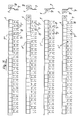
- the connector bar structure for the supply of electrical switches or modular electrical apparatus constituting the subject of the present invention comprises two or more rectilinear conductive strips or bars 1 intended to be housed in corresponding adjacent channels 2 defined by a casing 3 in the form of an elongate member open along one side.
- the casing 3 has two sides provided with enlarged edges 4 shaped in such a way as to be able to snap-engage a cover 5 along the longitudinal axis of which are formed a plurality of regularly spaced axially extending slots 6.
- the said strips or bars have a plurality of projections 7 extending in a regularly spaced array from one side.
- the ends 8 of the said projections 7 are suitably shaped and their spacing is correlated to the spacing of the slots 6.
- the width of each lateral projection 6 is such that it can project through a slot 6 to enable an electrical connection to be made thereto.
- each projection 7 is offset slightly from the general plane of the strip or bar 1 itself by a different amount for each bar 1 to correspond to the lateral spacing of a respective channel 2 of the casing from the longitudinal centre line at which the slots 6 are located, and each projection 7 has a weakened line 7 ⁇ close to its root to allow any unwanted projections to be broken off easily.
- This weakened, pre-fracture line 7 ⁇ is not so weak as to jeopardise the normal working of the connector, however.
- the said casing 3 receives two, three or four conductive strips or bars 1 according as it is desired to provide a bipolar, tripolar, or quadripolar distribution structure.
- any unwanted projections can be removed easily and the surplus connections which have been removed are indicated in Figure 3 in broken outline and identified with the reference numeral 7 ⁇ .
- Some of the strips or bars 1 have a connector tab 9 at one end for connection to an electrical supply, although it will be appreciated that electrical supply may be equally well made by connection to one of the lateral projections 7 either instead of or as well as connection to a terminal tab 9 at the end. This allows higher ratings to be achieved without overheating.
Landscapes
- Engineering & Computer Science (AREA)
- Power Engineering (AREA)
- Coupling Device And Connection With Printed Circuit (AREA)
- Multi-Conductor Connections (AREA)
Applications Claiming Priority (2)
| Application Number | Priority Date | Filing Date | Title |
|---|---|---|---|
| IT2100087U | 1987-03-03 | ||
| IT2100087U IT209984Z2 (it) | 1987-03-03 | 1987-03-03 | Struttura comprendente piu' sbarre conduttrici, connesse in un sistema polifase, per l'alimentazione di interruttori e di apparecchiature modulari. |
Publications (2)
| Publication Number | Publication Date |
|---|---|
| EP0280836A2 true EP0280836A2 (fr) | 1988-09-07 |
| EP0280836A3 EP0280836A3 (fr) | 1990-03-14 |
Family
ID=11175221
Family Applications (1)
| Application Number | Title | Priority Date | Filing Date |
|---|---|---|---|
| EP87830252A Withdrawn EP0280836A3 (fr) | 1987-03-03 | 1987-07-02 | Assemblage de connecteur pour la connexion avec interrupteurs, appareils électriques modulaires etc. |
Country Status (2)
| Country | Link |
|---|---|
| EP (1) | EP0280836A3 (fr) |
| IT (1) | IT209984Z2 (fr) |
Cited By (3)
| Publication number | Priority date | Publication date | Assignee | Title |
|---|---|---|---|---|
| GB2223630A (en) * | 1988-08-26 | 1990-04-11 | Lucas Ind Plc | A bus bar having a number of electrical contacts |
| FR2664755A1 (fr) * | 1990-07-16 | 1992-01-17 | Schrack Components Ag | Systeme de rails de raccordement. |
| US5295842A (en) * | 1991-06-25 | 1994-03-22 | Yazaki Corporation | Electric junction box |
Family Cites Families (2)
| Publication number | Priority date | Publication date | Assignee | Title |
|---|---|---|---|---|
| US2720632A (en) * | 1949-05-12 | 1955-10-11 | Frank Adam Electric Co | Bus duct and branch circuit connector for power distribution systems |
| FR2537377B1 (fr) * | 1982-12-06 | 1985-07-05 | Hager Electro | Dispositif d'alimentation ou de pontage pour appareils electriques modulaires juxtaposes et elements de ce dispositif |
-
1987
- 1987-03-03 IT IT2100087U patent/IT209984Z2/it active
- 1987-07-02 EP EP87830252A patent/EP0280836A3/fr not_active Withdrawn
Cited By (4)
| Publication number | Priority date | Publication date | Assignee | Title |
|---|---|---|---|---|
| GB2223630A (en) * | 1988-08-26 | 1990-04-11 | Lucas Ind Plc | A bus bar having a number of electrical contacts |
| GB2223630B (en) * | 1988-08-26 | 1992-07-15 | Lucas Ind Plc | Improvements relating to a bus bar having a number of electrical contacts |
| FR2664755A1 (fr) * | 1990-07-16 | 1992-01-17 | Schrack Components Ag | Systeme de rails de raccordement. |
| US5295842A (en) * | 1991-06-25 | 1994-03-22 | Yazaki Corporation | Electric junction box |
Also Published As
| Publication number | Publication date |
|---|---|
| IT8721000V0 (it) | 1987-03-03 |
| EP0280836A3 (fr) | 1990-03-14 |
| IT209984Z2 (it) | 1988-11-14 |
Similar Documents
| Publication | Publication Date | Title |
|---|---|---|
| US4582377A (en) | Cross connection link for modular terminal blocks | |
| PL175151B1 (pl) | Zacisk szeregowy | |
| US5008493A (en) | Holder with busbars for a busbar system | |
| US4157582A (en) | Plug-in contact structure for panelboard | |
| US3263131A (en) | Electric power busway with plug-in branch circuit takeoff | |
| EP0434964A1 (fr) | Ensemble d'éléments de construction pour aider la connexion électrique simultanée de plusieurs interrupteurs automatiques modulaires | |
| US3391378A (en) | Plug-in type high frequency busway | |
| US5224881A (en) | Connection strip having semi-integrated protectors | |
| US5151043A (en) | Electrical power distribution busway with isolated ground bus | |
| CN1161813C (zh) | 模块式电气装置 | |
| DE4327715A1 (de) | Vorrichtung zum Zuführen elektrischer Energie zu wenistens einem elektrischen Installationsgerät | |
| JPH0349237B2 (fr) | ||
| EP0280836A2 (fr) | Assemblage de connecteur pour la connexion avec interrupteurs, appareils électriques modulaires etc. | |
| EP0121223B1 (fr) | Barrette de répartition avec une multitude de bornes doubles pour le raccordement auxquelles le dénudage des conducteurs électriques n'est pas nécessaire | |
| CA2202536A1 (fr) | Conducteur electrique souple | |
| EP1130683A1 (fr) | Dispositif de distribution d'énergie | |
| US2897410A (en) | Plug-in type circuit breaker panelboard | |
| US3745229A (en) | Duct and electrical connector assembly | |
| US2960674A (en) | Multiphase power distributing apparatus | |
| CN1054477C (zh) | 用于一系列开关设备的供电分配器 | |
| US4417781A (en) | Dielectric separation of incoming and outgoing terminations in a cable termination block | |
| CN101227047B (zh) | 容许移植喙连接的双层连接桥接装置 | |
| EA001041B1 (ru) | Устройство для сборки и электрического подсоединения модульных электрических распределительных узлов, таких как выключатели | |
| US4492419A (en) | Electric distribution center | |
| US2862117A (en) | Bus bar distribution system |
Legal Events
| Date | Code | Title | Description |
|---|---|---|---|
| PUAI | Public reference made under article 153(3) epc to a published international application that has entered the european phase |
Free format text: ORIGINAL CODE: 0009012 |
|
| AK | Designated contracting states |
Kind code of ref document: A2 Designated state(s): BE CH DE ES FR GB LI NL SE |
|
| PUAL | Search report despatched |
Free format text: ORIGINAL CODE: 0009013 |
|
| AK | Designated contracting states |
Kind code of ref document: A3 Designated state(s): BE CH DE ES FR GB LI NL SE |
|
| 17P | Request for examination filed |
Effective date: 19900706 |
|
| 17Q | First examination report despatched |
Effective date: 19911223 |
|
| STAA | Information on the status of an ep patent application or granted ep patent |
Free format text: STATUS: THE APPLICATION IS DEEMED TO BE WITHDRAWN |
|
| 18D | Application deemed to be withdrawn |
Effective date: 19921006 |