EP0280850B1 - Turbo-Arbeitsmaschine radialer Bauart mit Scheibendiffusor - Google Patents
Turbo-Arbeitsmaschine radialer Bauart mit Scheibendiffusor Download PDFInfo
- Publication number
- EP0280850B1 EP0280850B1 EP88100577A EP88100577A EP0280850B1 EP 0280850 B1 EP0280850 B1 EP 0280850B1 EP 88100577 A EP88100577 A EP 88100577A EP 88100577 A EP88100577 A EP 88100577A EP 0280850 B1 EP0280850 B1 EP 0280850B1
- Authority
- EP
- European Patent Office
- Prior art keywords
- diffuser
- disc
- turbine
- processing machine
- radial
- Prior art date
- Legal status (The legal status is an assumption and is not a legal conclusion. Google has not performed a legal analysis and makes no representation as to the accuracy of the status listed.)
- Expired - Lifetime
Links
- 230000003068 static effect Effects 0.000 claims abstract description 5
- 238000010276 construction Methods 0.000 claims 2
- 230000001419 dependent effect Effects 0.000 claims 1
- 238000009826 distribution Methods 0.000 description 4
- 230000002093 peripheral effect Effects 0.000 description 4
- 230000006399 behavior Effects 0.000 description 2
- 230000000694 effects Effects 0.000 description 2
- 230000002411 adverse Effects 0.000 description 1
- 230000005284 excitation Effects 0.000 description 1
- 230000002045 lasting effect Effects 0.000 description 1
- 230000034958 pharyngeal pumping Effects 0.000 description 1
Images

Classifications
-
- F—MECHANICAL ENGINEERING; LIGHTING; HEATING; WEAPONS; BLASTING
- F04—POSITIVE - DISPLACEMENT MACHINES FOR LIQUIDS; PUMPS FOR LIQUIDS OR ELASTIC FLUIDS
- F04D—NON-POSITIVE-DISPLACEMENT PUMPS
- F04D29/00—Details, component parts, or accessories
- F04D29/40—Casings; Connections of working fluid
- F04D29/42—Casings; Connections of working fluid for radial or helico-centrifugal pumps
- F04D29/44—Fluid-guiding means, e.g. diffusers
- F04D29/46—Fluid-guiding means, e.g. diffusers adjustable
-
- F—MECHANICAL ENGINEERING; LIGHTING; HEATING; WEAPONS; BLASTING
- F04—POSITIVE - DISPLACEMENT MACHINES FOR LIQUIDS; PUMPS FOR LIQUIDS OR ELASTIC FLUIDS
- F04D—NON-POSITIVE-DISPLACEMENT PUMPS
- F04D29/00—Details, component parts, or accessories
- F04D29/40—Casings; Connections of working fluid
- F04D29/42—Casings; Connections of working fluid for radial or helico-centrifugal pumps
- F04D29/44—Fluid-guiding means, e.g. diffusers
- F04D29/441—Fluid-guiding means, e.g. diffusers especially adapted for elastic fluid pumps
-
- F—MECHANICAL ENGINEERING; LIGHTING; HEATING; WEAPONS; BLASTING
- F05—INDEXING SCHEMES RELATING TO ENGINES OR PUMPS IN VARIOUS SUBCLASSES OF CLASSES F01-F04
- F05D—INDEXING SCHEME FOR ASPECTS RELATING TO NON-POSITIVE-DISPLACEMENT MACHINES OR ENGINES, GAS-TURBINES OR JET-PROPULSION PLANTS
- F05D2250/00—Geometry
- F05D2250/50—Inlet or outlet
- F05D2250/52—Outlet
Definitions
- the invention relates to a turbo working machine of radial type according to the preamble of claim 1.
- the diffusers are used in radial radial turbomachinery to reduce the flow velocity of the medium and to convert it into static pressure.
- the known disc diffusers can be parallel-walled, or conically narrow or widen outwards.
- the disc diffusers can be provided with or without guide vanes, these guide vanes being fixed or adjustable.
- the known disk diffusers can be profiled axially in order to change special properties of the turbomachine, for example in order to act on the surge limit.
- the disk diffusers can also be axially adjustable to influence the control behavior of the turbomachine.
- rotationally asymmetrical pressure distributions can be caused by disturbing bodies, local openings, discontinuous cross-sections and over- or under-loaded spirals.
- the known disc diffusers pass on the influences of this rotationally asymmetrical flow retroactively to the impeller.
- the resulting pressure differences on the circumference have a lasting influence on the operating behavior of the turbomachine, reduce the efficiency and have a vibration-stimulating effect on the blades of the impeller.
- Turbocharger is known from US Pat. No. 3,072,512, the compressor of which has a diffuser channel which is delimited on one side by a ring.
- the ring has a spiral inner and a spiral outer edge, so that a diffuser channel of constantly changing radial length is created.
- the compressor part of a turbocharger known from DE-A 1 451 895 has a diffuser channel which is delimited by a fixed guide ring and an axially adjustable guide ring. With the help of the adjustable guide ring, the axial width of the diffuser channel is changed during operation in order to maintain a constant pressure regardless of the speed of the drive unit.
- the invention has for its object to design the generic radial turbo machine so that the adverse effects of peripheral pressure differences are mitigated.
- the disc diffuser designed according to the invention can be set to a lower local pressure on the periphery of the disc diffuser in such a way that the pressure at this point is increased by the locally different radial length of the diffuser channel.
- the disc diffuser can also track the rotation of the peripheral pressure profile when the operating load changes. As a result, the peripheral pressure distribution behind the impeller is made more uniform and the impeller is applied more evenly. This leveling of the pressure distribution and the impingement of the impeller improve the efficiency and the pumping behavior of the turbo machine.
- the vibration excitation of the impeller blades is reduced by the now smaller rotational asymmetries of the pressure.
- the previously very complex spirals can be replaced by simple rotationally symmetrical collecting spaces, since the aerodynamic disadvantages of such collecting spaces are compensated for.
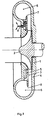
- An impeller 2 rotates in a housing 1 of a turbo working machine which is only partially shown. Radially above the impeller 2 is the diffuser channel 3 of a disk diffuser, in which the flow velocity of the medium is reduced and converted into static pressure.
- the diffuser channel 3 is formed by the rear wall 4 of the housing 1 and an annular diffuser disc 5.
- the diffuser channel 3 opens into a collecting space 6, which is formed within the housing 1.
- a connecting piece (not shown) for removing the medium connects to the collecting space 6.
- the collecting space 6 is preferably rotationally symmetrical and can have an annular cross section. The collecting space 6 can also expand continuously towards the outlet nozzle.
- the diffuser disc 5 is held in the housing 1 so as to be rotatable about the axis of rotation of the impeller 2 and is connected to a lever arrangement 9.
- the diffuser disc 5 can be rotated relative to the housing 1 by a certain angle via this lever arrangement 9.
- the radial length of the diffuser channel 3 differs locally.
- the radially outer edge of the diffuser disc 5 is formed by a spiral curve. At one point the curve is drawn inwards, so that a closed line 7 with a bulge 8 is created.
- the radially outer boundary of the diffuser channel 3 formed by the rear wall 3 and the diffuser disk 5 follows the outer contour of the diffuser disk 5, so that the diffuser channel 3 is also of different lengths in the radial direction as viewed over the cross section.
- the diffuser disc becomes be 5 rotated so that the local position of the pressure sink corresponds to the bulge 8 of the diffuser disc 5.
- the pressure sinks mentioned can migrate in the circumferential direction with the load state of the turbo working machine.
- the pressure profile on the circumference of the disc diffuser can be determined for each load point.
- a certain angular position of the disk diffuser 5 is assigned to each load point.
- the disc diffuser can then be adjusted according to the load, so that the static pressure is always distributed as evenly as possible around the circumference of the disc diffuser.
Landscapes
- Engineering & Computer Science (AREA)
- Mechanical Engineering (AREA)
- General Engineering & Computer Science (AREA)
- Structures Of Non-Positive Displacement Pumps (AREA)
- Nozzles (AREA)
- Non-Positive Displacement Air Blowers (AREA)
- Motor Or Generator Frames (AREA)
Description
- Die Erfindung betrifft eine Turbo-Arbeitsmaschine radialer Bauart nach dem Oberbegriff des Anspruches 1.
- Die Diffusoren dienen in Turbo-Arbeitsmaschinen radialer Bauart dazu, die Strömungsgeschwindigkeit des Mediums zu reduzieren und in statischen Druck umzuwandeln. Die bekannten Scheibendiffusoren können parallelwandig sein, oder sich nach außen konisch verengen oder erweitern. Die Scheibendiffusoren können ohne oder mit Leitschaufeln versehen sein, wobei diese Leitschaufein fest oder verstellbar sind. Weiterhin können die bekannten Scheibendiffusoren axial profiliert sein, um besondere Eigenschaften der Turbomaschine zu verändern, zum Beispiel um auf die Pumpgrenze einzuwirken. Schließlich können die Scheibendiffusoren auch zur Beeinflussung des Regelverhaltens der Turbomaschine axial verstellbar sein.
- In den Gehäusen von Turbo-Arbeitsmaschinen radialer Bauart können rotationsunsymmetrische Druckverteilungen durch Störkörper, lokale Öffnungen, diskontinuierliche Querschnitte und über-oder unterbelastete Spirale hervorgerufen werden. Die bekannten Scheibendiffusoren leiten die Einflüsse dieser rotationsunsymmetrischen Strömung rückwirkend auf das Laufrad weiter. Die daraus resultierenden Druckunterschiede am Umfang beeinflussen das Betriebsverhalten der Turbomaschine nachhaltig, mindern den Wirkungsgrad und wirken schwingungsanregend auf die Schaufeln des Laufrades.
- Aus der US-A 3 072 512 ist Turbolader bekannt, dessen Verdichter einen Diffusorkanal aufweist, der auf einer Seite durch einen Ring begrenzt ist. Der Ring weist eine spiralförmig verlaufende innere und eine spiralförmig verlaufende äußere Kante auf, so daß ein Diffusorkanal von sich stetig ändernder radialer Länge entsteht.
- Der Verdichterteil eines aus der DE-A 1 451 895 bekannten Turboladers weist einen Diffusorkanal auf, der durch einen fest angeordneten Leitring und einen axial verstellbaren Leitring begrenzt ist. Mit Hilfe des verstellbaren Leitringes wird die axiale Breite des Diffusorkanals während des Betriebes verändert, um unabhängig von der Drehzahl des Antriebsaggregates einen konstanten Druck zu halten.
- Der Erfindung liegt die Aufgabe zugrunde, die gattungsgemäße radiale Turbo-Arbeitsmaschine derart zu gestalten, daß die nachteiligen Auswirkungen peripherer Druckunterschiede abgeschwächt werden.
- Diese Aufgabe wird bei einer gattungsgemäßen Turbo-Arbeitsmaschine erfindungsgemäß durch die kennzeichnenden Merkmale des Anspruches 1 gelöst. Vorteilhafte Ausgestaltungen der Erfindung sind in den Unteransprüchen angegeben.
- Der erfindungsgemäß ausgebildete Scheibendiffusor kann derart auf einen geringeren örtlichen Druck am Umfang des Scheibendiffusors eingestellt werden, daß durch die örtlich unterschiedliche radiale Länge des Diffusorkanals der Druck an dieser Stelle angehoben wird. Der Scheibendiffusor kann auch bei einer Änderung der Betriebslast der Verdrehung des peripheren Druckprofils nachgeführt werden. Damit wird die periphere Druckverteilung hinter dem Laufrad insgesamt vergleichmäßigt und das Laufrad gleichmäßiger beaufschlagt. Durch diese Vergleichmäßigung der Druckverteilung und der Beaufschlagung des Laufrades werden der Wirkungsgrad und das Pumpverhalten der Turbo-Arbeitsmaschine verbessert. Die Schwingungsanregung der Laufradschaufeln durch nunmehr kleinere Rotationsunsymmetrien des Druckes wird gemildert. Die bisher sehr aufwendigen Spiralen können durch einfache rotationssymmetrische Sammelräume ersetzt werden, da die aerodynamischen Nachteile solcher Sammelräume kompensiert werden.
- Ein Ausführungsbeispiel der Erfindung ist in der Zeichnung dargestellt und wird im folgenden näher beschrieben. Es zeigen:
- Fig. 1 den Schnitt durch eine Turbo-Arbeitsmaschine gemäß der Erfindung und
- Fig. 2 die Ansicht auf eine Scheibe des Scheibendiffusors.
- In einem nur teilweise gezeigten Gehäuse 1 einer Turbo-Arbeitsmaschine läuft ein Laufrad 2 um. Radial über dem Laufrad 2 befindet sich der Diffusorkanal 3 eines Scheibendiffusors, in dem die Strömungsgeschwindigkeit des Mediums reduziert und in statischen Druck umgewandelt wird. Der Diffusorkanal 3 ist von der Rückwand 4 des Gehäuses 1 und einer ringförmigen Diffusorscheibe 5 gebildet. Der Diffusorkanal 3 mündet in einen Sammelraum 6 ein, der innerhalb des Gehäuses 1 gebildet ist. An den Sammelraum 6 schließt sich ein nicht gezeigter Stutzen zur Abführung des Mediums an. Aufgrund der nachfolgend beschriebenen Ausbildung des Scheibendiffusors ist der Sammelraum 6 vorzugsweise rotationssymmetrisch und kann einen kreisringförmigen Querschnitt aufweisen. Der Sammelraum 6 kann sich auch zum Austrittsstutzen hin kontinuierlich erweitern.
- Die Diffusorscheibe 5 ist um die Rotationsachse des Laufrades 2 drehbar in dem Gehäuse 1 gehalten und mit einer Hebelanordnung 9 verbunden. Über diese Hebelanordnung 9 kann die Diffusorscheibe 5 um einen bestimmten Winkel relativ zum Gehäuse 1 gedreht werden.
- Die radiale Länge des Diffusorkanals 3 ist örtlich unterschiedlich groß. Wie am besten aus Fig. 2 zu ersehen ist, ist der radial äußere Rand der Diffusorscheibe 5 durch eine spiralförmige Kurve gebildet. An einer Stelle ist die Kurve nach innen eingezogen, so daß eine geschlossene Linie 7 mit einer Ausbuchtung 8 entstanden ist. Die radial äußere Begrenzung des durch die Rückwand 3 und die Diffusorscheibe 5 gebildeten Diffusorkanals 3 folgt der Außenkontur der Diffusorscheibe 5, so daß auch der Diffusorkanal 3 über den Querschnitt gesehen in radialer Richtung unterschiedlich lang ist.
- Tritt nun in der Turbo-Arbeitsmaschine eine ungleichmäßige periphere Druckverteilung durch eine örtliche Drucksenke auf, so wird die Diffusorscheibe 5 so gedreht, daß die örtliche Lage der Drucksenke mit der Ausbuchtung 8 der Diffusorscheibe 5 übereinstimmt. Die erwähnten Drucksenken können mit dem Lastzustand der Turbo-Arbeitsmaschine in Umfangsrichtung wandern. Vor der inbetriebnahme einer neuen Turbo-Arbeitsmaschine kann für jeden Lastpunkt das Druckprofil am Umfang des Scheibendiffusors bestimmt werden. Jedem Lastpunkt wird eine bestimmte Winkelstellung des Scheibendiffusors 5 zugeordnet. Im Betrieb kann dann der Scheibendiffusor entsprechend der Last verstellt werden, so daß stets eine möglichst gleichmäßige Verteilung des statischen Druckes am Umfang des Scheibendiffusors herrscht.
Claims (4)
Priority Applications (1)
| Application Number | Priority Date | Filing Date | Title |
|---|---|---|---|
| AT88100577T ATE59439T1 (de) | 1987-03-05 | 1988-01-16 | Turbo-arbeitsmaschine radialer bauart mit scheibendiffusor. |
Applications Claiming Priority (2)
| Application Number | Priority Date | Filing Date | Title |
|---|---|---|---|
| DE3707103A DE3707103C1 (de) | 1987-03-05 | 1987-03-05 | Turbo-Arbeitsmaschine radialer Bauart mit Scheibendiffusor |
| DE3707103 | 1987-03-05 |
Publications (3)
| Publication Number | Publication Date |
|---|---|
| EP0280850A2 EP0280850A2 (de) | 1988-09-07 |
| EP0280850A3 EP0280850A3 (en) | 1989-08-02 |
| EP0280850B1 true EP0280850B1 (de) | 1990-12-27 |
Family
ID=6322356
Family Applications (1)
| Application Number | Title | Priority Date | Filing Date |
|---|---|---|---|
| EP88100577A Expired - Lifetime EP0280850B1 (de) | 1987-03-05 | 1988-01-16 | Turbo-Arbeitsmaschine radialer Bauart mit Scheibendiffusor |
Country Status (7)
| Country | Link |
|---|---|
| US (1) | US4824323A (de) |
| EP (1) | EP0280850B1 (de) |
| JP (1) | JPS63253197A (de) |
| AT (1) | ATE59439T1 (de) |
| DE (2) | DE3707103C1 (de) |
| ES (1) | ES2019408B3 (de) |
| GR (1) | GR3001250T3 (de) |
Families Citing this family (2)
| Publication number | Priority date | Publication date | Assignee | Title |
|---|---|---|---|---|
| US9353765B2 (en) * | 2008-02-20 | 2016-05-31 | Trane International Inc. | Centrifugal compressor assembly and method |
| JP6128230B2 (ja) | 2013-10-31 | 2017-05-17 | 株式会社Ihi | 遠心圧縮機及び過給機 |
Family Cites Families (12)
| Publication number | Priority date | Publication date | Assignee | Title |
|---|---|---|---|---|
| DE30288C (de) * | J. bubbe, Ober-Telegraphen-Assistent in Hamburg | Telephon-Uebertragungs-System | ||
| DE464970C (de) * | 1927-02-21 | 1928-09-01 | Oscar Simmen | Kreiselmaschine mit durch axial verstellbare Regelmittel veraenderbarem Durchgangsquerschnitt im Diffusor oder Leitrad |
| US2285976A (en) * | 1940-01-15 | 1942-06-09 | Gen Electric | Centrifugal compressor |
| GB768799A (en) * | 1954-07-21 | 1957-02-20 | Cleaver Brookes Company | Improvements in or relating to fan structure |
| NL98031C (de) * | 1957-12-23 | |||
| US3073512A (en) * | 1958-06-16 | 1963-01-15 | Thompson Ramo Wooldridge Inc | Turbocharger fence ring |
| GB1011716A (en) * | 1964-03-13 | 1965-12-01 | Caterpillar Tractor Co | Turbine-driven charger for an internal combustion engine |
| CH451711A (de) * | 1964-07-14 | 1968-05-15 | Emile Egger & Cie S A | Mehrzweck-Pumpenaggregat |
| US3868196A (en) * | 1974-03-29 | 1975-02-25 | Gen Electric | Centrifugal compressor with rotating vaneless diffuser powered by leakage flow |
| US3941501A (en) * | 1974-11-18 | 1976-03-02 | Avco Corporation | Diffuser including a rotary stage |
| US4181466A (en) * | 1977-03-17 | 1980-01-01 | Wallace Murray Corp. | Centrifugal compressor and cover |
| JPS54104007A (en) * | 1978-02-01 | 1979-08-15 | Hitachi Ltd | Diffuser for centrifugal compressor |
-
1987
- 1987-03-05 DE DE3707103A patent/DE3707103C1/de not_active Expired - Lifetime
-
1988
- 1988-01-16 DE DE8888100577T patent/DE3861390D1/de not_active Expired - Lifetime
- 1988-01-16 ES ES88100577T patent/ES2019408B3/es not_active Expired - Lifetime
- 1988-01-16 AT AT88100577T patent/ATE59439T1/de not_active IP Right Cessation
- 1988-01-16 EP EP88100577A patent/EP0280850B1/de not_active Expired - Lifetime
- 1988-03-02 JP JP63049468A patent/JPS63253197A/ja active Pending
- 1988-03-04 US US07/164,102 patent/US4824323A/en not_active Expired - Fee Related
-
1990
- 1990-12-28 GR GR90401055T patent/GR3001250T3/el unknown
Also Published As
| Publication number | Publication date |
|---|---|
| ATE59439T1 (de) | 1991-01-15 |
| US4824323A (en) | 1989-04-25 |
| ES2019408B3 (es) | 1991-06-16 |
| DE3707103C1 (de) | 1988-01-28 |
| DE3861390D1 (de) | 1991-02-07 |
| EP0280850A3 (en) | 1989-08-02 |
| GR3001250T3 (en) | 1992-07-30 |
| EP0280850A2 (de) | 1988-09-07 |
| JPS63253197A (ja) | 1988-10-20 |
Similar Documents
| Publication | Publication Date | Title |
|---|---|---|
| DE2632155C3 (de) | Gasturbinenstrahltriebwerk | |
| EP3408503B1 (de) | Strömungsmaschine mit beschaufeltem diffusor | |
| EP0614014B1 (de) | Radialverdichter mit einem strömungsstabilisierenden Gehäuse | |
| EP2993357B1 (de) | Radialverdichterstufe | |
| DE102013101133A1 (de) | Gebläsebaugruppe | |
| EP2824282A1 (de) | Gasturbine mit Hochdruckturbinenkühlsystem | |
| EP2921716B1 (de) | Schaufelreihengruppe | |
| DE2042478A1 (de) | Gasturbinenstrahltriebwerk für Flugzeuge mit Einrichtungen zur Bauteilkühlung und Verdichterregelung | |
| DE102017122524A1 (de) | Diffusor für einen Verdichter | |
| EP0118769A2 (de) | Mehrstufige Deckbandturbine | |
| EP0348342A1 (de) | Kreiselmaschine mit gegenläufigen Laufrädern und Verwendung der Kreiselmaschine | |
| EP3682092A1 (de) | Diffusor einer abgasturbine | |
| EP0131719B1 (de) | Verstellbarer Leitapparat | |
| DE949899C (de) | Axialgeblaese oder -pumpe mit Schwenkbaren Laufschaufeln | |
| DE112019003298T5 (de) | Turbine und Turbolader | |
| EP0684386A1 (de) | Verfahren und Vorrichtung zur Förderung eines Fluides | |
| DE102007027396A1 (de) | Strömungsmaschine | |
| DE102014219058A1 (de) | Radialverdichterlaufrad und zugehöriger Radialverdichter | |
| DE102017118950A1 (de) | Diffusor für einen Radialverdichter | |
| DE112014003154B4 (de) | Spiralstruktur und Turbolader | |
| DE102011106525A1 (de) | Dispergierpumpe | |
| DE3707103C1 (de) | Turbo-Arbeitsmaschine radialer Bauart mit Scheibendiffusor | |
| CH714389B1 (de) | Radialverdichter. | |
| DE2436458A1 (de) | Kreiselverdichter | |
| DE102017114007A1 (de) | Diffusor für einen Radialverdichter |
Legal Events
| Date | Code | Title | Description |
|---|---|---|---|
| PUAI | Public reference made under article 153(3) epc to a published international application that has entered the european phase |
Free format text: ORIGINAL CODE: 0009012 |
|
| AK | Designated contracting states |
Kind code of ref document: A2 Designated state(s): AT BE CH DE ES FR GB GR IT LI LU NL SE |
|
| PUAL | Search report despatched |
Free format text: ORIGINAL CODE: 0009013 |
|
| RHK1 | Main classification (correction) |
Ipc: F04D 29/44 |
|
| AK | Designated contracting states |
Kind code of ref document: A3 Designated state(s): AT BE CH DE ES FR GB GR IT LI LU NL SE |
|
| 17P | Request for examination filed |
Effective date: 19891006 |
|
| 17Q | First examination report despatched |
Effective date: 19891204 |
|
| RAP1 | Party data changed (applicant data changed or rights of an application transferred) |
Owner name: DEUTSCHE BABCOCK-BORSIG AG |
|
| GRAA | (expected) grant |
Free format text: ORIGINAL CODE: 0009210 |
|
| AK | Designated contracting states |
Kind code of ref document: B1 Designated state(s): AT BE CH DE ES FR GB GR IT LI LU NL SE |
|
| REF | Corresponds to: |
Ref document number: 59439 Country of ref document: AT Date of ref document: 19910115 Kind code of ref document: T |
|
| ET | Fr: translation filed | ||
| REF | Corresponds to: |
Ref document number: 3861390 Country of ref document: DE Date of ref document: 19910207 |
|
| ITF | It: translation for a ep patent filed | ||
| GBT | Gb: translation of ep patent filed (gb section 77(6)(a)/1977) | ||
| PLBE | No opposition filed within time limit |
Free format text: ORIGINAL CODE: 0009261 |
|
| STAA | Information on the status of an ep patent application or granted ep patent |
Free format text: STATUS: NO OPPOSITION FILED WITHIN TIME LIMIT |
|
| 26N | No opposition filed | ||
| REG | Reference to a national code |
Ref country code: GR Ref legal event code: FG4A Free format text: 3001250 |
|
| PGFP | Annual fee paid to national office [announced via postgrant information from national office to epo] |
Ref country code: GB Payment date: 19930111 Year of fee payment: 6 Ref country code: DE Payment date: 19930111 Year of fee payment: 6 |
|
| PGFP | Annual fee paid to national office [announced via postgrant information from national office to epo] |
Ref country code: FR Payment date: 19930112 Year of fee payment: 6 |
|
| PGFP | Annual fee paid to national office [announced via postgrant information from national office to epo] |
Ref country code: SE Payment date: 19930114 Year of fee payment: 6 |
|
| PGFP | Annual fee paid to national office [announced via postgrant information from national office to epo] |
Ref country code: CH Payment date: 19930115 Year of fee payment: 6 |
|
| PGFP | Annual fee paid to national office [announced via postgrant information from national office to epo] |
Ref country code: AT Payment date: 19930118 Year of fee payment: 6 |
|
| PGFP | Annual fee paid to national office [announced via postgrant information from national office to epo] |
Ref country code: LU Payment date: 19930119 Year of fee payment: 6 |
|
| PGFP | Annual fee paid to national office [announced via postgrant information from national office to epo] |
Ref country code: ES Payment date: 19930127 Year of fee payment: 6 |
|
| PGFP | Annual fee paid to national office [announced via postgrant information from national office to epo] |
Ref country code: BE Payment date: 19930128 Year of fee payment: 6 |
|
| PGFP | Annual fee paid to national office [announced via postgrant information from national office to epo] |
Ref country code: NL Payment date: 19930131 Year of fee payment: 6 Ref country code: GR Payment date: 19930131 Year of fee payment: 6 |
|
| EPTA | Lu: last paid annual fee | ||
| PG25 | Lapsed in a contracting state [announced via postgrant information from national office to epo] |
Ref country code: LU Free format text: LAPSE BECAUSE OF NON-PAYMENT OF DUE FEES Effective date: 19940116 Ref country code: GB Effective date: 19940116 Ref country code: AT Effective date: 19940116 |
|
| PG25 | Lapsed in a contracting state [announced via postgrant information from national office to epo] |
Ref country code: SE Effective date: 19940117 Ref country code: ES Free format text: LAPSE BECAUSE OF NON-PAYMENT OF DUE FEES Effective date: 19940117 |
|
| PG25 | Lapsed in a contracting state [announced via postgrant information from national office to epo] |
Ref country code: LI Effective date: 19940131 Ref country code: CH Effective date: 19940131 Ref country code: BE Effective date: 19940131 |
|
| BERE | Be: lapsed |
Owner name: DEUTSCHE BABCOCK-BORSIG A.G. Effective date: 19940131 |
|
| PG25 | Lapsed in a contracting state [announced via postgrant information from national office to epo] |
Ref country code: GR Free format text: THE PATENT HAS BEEN ANNULLED BY A DECISION OF A NATIONAL AUTHORITY Effective date: 19940731 |
|
| PG25 | Lapsed in a contracting state [announced via postgrant information from national office to epo] |
Ref country code: NL Effective date: 19940801 |
|
| GBPC | Gb: european patent ceased through non-payment of renewal fee |
Effective date: 19940116 |
|
| NLV4 | Nl: lapsed or anulled due to non-payment of the annual fee | ||
| PG25 | Lapsed in a contracting state [announced via postgrant information from national office to epo] |
Ref country code: FR Effective date: 19940930 |
|
| REG | Reference to a national code |
Ref country code: CH Ref legal event code: PL |
|
| PG25 | Lapsed in a contracting state [announced via postgrant information from national office to epo] |
Ref country code: DE Effective date: 19941001 |
|
| REG | Reference to a national code |
Ref country code: FR Ref legal event code: ST |
|
| REG | Reference to a national code |
Ref country code: GR Ref legal event code: MM2A Free format text: 3001250 |
|
| EUG | Se: european patent has lapsed |
Ref document number: 88100577.1 Effective date: 19940810 |
|
| REG | Reference to a national code |
Ref country code: ES Ref legal event code: FD2A Effective date: 19990301 |
|
| PG25 | Lapsed in a contracting state [announced via postgrant information from national office to epo] |
Ref country code: IT Free format text: LAPSE BECAUSE OF NON-PAYMENT OF DUE FEES;WARNING: LAPSES OF ITALIAN PATENTS WITH EFFECTIVE DATE BEFORE 2007 MAY HAVE OCCURRED AT ANY TIME BEFORE 2007. THE CORRECT EFFECTIVE DATE MAY BE DIFFERENT FROM THE ONE RECORDED. Effective date: 20050116 |