EP0280864A2 - Tête d'impression à aiquilles - Google Patents
Tête d'impression à aiquilles Download PDFInfo
- Publication number
- EP0280864A2 EP0280864A2 EP19880100870 EP88100870A EP0280864A2 EP 0280864 A2 EP0280864 A2 EP 0280864A2 EP 19880100870 EP19880100870 EP 19880100870 EP 88100870 A EP88100870 A EP 88100870A EP 0280864 A2 EP0280864 A2 EP 0280864A2
- Authority
- EP
- European Patent Office
- Prior art keywords
- needle
- hinged
- armature
- yoke
- folding
- Prior art date
- Legal status (The legal status is an assumption and is not a legal conclusion. Google has not performed a legal analysis and makes no representation as to the accuracy of the status listed.)
- Granted
Links
Images
Classifications
-
- B—PERFORMING OPERATIONS; TRANSPORTING
- B41—PRINTING; LINING MACHINES; TYPEWRITERS; STAMPS
- B41J—TYPEWRITERS; SELECTIVE PRINTING MECHANISMS, i.e. MECHANISMS PRINTING OTHERWISE THAN FROM A FORME; CORRECTION OF TYPOGRAPHICAL ERRORS
- B41J2/00—Typewriters or selective printing mechanisms characterised by the printing or marking process for which they are designed
- B41J2/22—Typewriters or selective printing mechanisms characterised by the printing or marking process for which they are designed characterised by selective application of impact or pressure on a printing material or impression-transfer material
- B41J2/23—Typewriters or selective printing mechanisms characterised by the printing or marking process for which they are designed characterised by selective application of impact or pressure on a printing material or impression-transfer material using print wires
- B41J2/27—Actuators for print wires
- B41J2/275—Actuators for print wires of clapper type
Definitions
- the invention relates to a needle print head comprising a plurality of ring-shaped armature magnets arranged in a ring around a needle guide, each with a U-shaped magnet yoke, a magnet coil surrounding a U-leg and an at least approximately radially directed armature armature, which is firmly connected at its radially inner end to a pressure needle and is biased by spring force into its rest position, which is defined by a stop.
- the hinged armature is suspended at its radially outer end on a spring clip and rests on the radially outer yoke leg in such a way that it can be tilted about the radially outer edge of the yoke leg surface facing it is.
- a first disadvantage of this solution lies in the fact that the yoke leg and the hinged armature resting against it rub against one another during the movement of the latter, as a result of which a relatively strong and undefined wear of the abutting surfaces occurs. As a result, the quality of the print image of such a needle printhead changes after a long period of operation.
- the folding anchor is mounted on the one yoke leg about a fixed pivot axis, a return spring acting on its short lever arm remote from the printing needle. Because of this unfavorable leverage ratio, the hinged anchor also has the disadvantages discussed above. Furthermore, in this embodiment, the hinged anchor is not firmly connected to the pressure needle, but strikes the pressure needle biased into its rest position by its own return spring. Since the pressure needle on the one hand and the hinged armature on the other hand represent two oscillating systems that do not have identical oscillation sizes, the oscillation behavior of the two oscillation systems can be significantly different at suitable operating frequencies. On the one hand, this can lead to increased wear on the pressure needle and the hinged anchor, and on the other hand, it can produce silhouettes.
- the invention has for its object to provide a dot-matrix print head of the type mentioned, which is easy to manufacture and assemble, has a long service life, enables a high operating frequency and also ensures a clean typeface in all layers of the same without copies without the generation of silhouettes .
- the hinged armature is pivotally mounted at its radially outer end by means of a cylindrical pin about its axis and that a return spring engages at a location of the hinged armature located between the pressure needle and the radially inner yoke leg.
- the folding anchor has a spatially fixed, defined pivot axis.
- the cylindrical pins can be made with simple means manufacture very precisely.
- the abutting bearing surfaces of the pin on the one hand and the plastic bearing parts receiving it on the other hand are subject to low wear and tear, which is also carried out at least approximately in the same size and in the same way for all hinged anchors.
- the elasticity of the plastic allows the pin to be clipped in. This means that the hinged anchor can be quickly installed without careful adjustment. At the same time, the plastic ensures little wear on the bearing pin.
- the storage forks can be easily and precisely manufactured as injection molded parts.
- a return spring preferably engages at a point of the hinged armature located between the pressure needle and the radially inner yoke leg. Since, in the solution according to the invention, the hinged armature is designed as a one-armed lever and the return spring acts on the hinged armature relatively far from the bearing axis, tolerances in the spring strength or in the distance of the point of application of the spring on the hinged armature from the bearing axis affect the impact force of the pressure needle hardly out. Therefore, the impact force of various new hinged anchors in the solution according to the invention is within a very narrow tolerance range.
- the needle print head according to the invention thus provides a very uniform typeface. Because of the arrangement of the return spring relatively close to the pressure needle, the rebound of the hinged armature against the stop is also reduced, so that the danger of creating silhouettes at high operating frequencies is avoided.
- the mounting of the bearing forks on the magnetic yoke can be done in a simple manner in that the bearing forks are connected to one another by a metal web which is attached to the radially outer yoke leg, for example by spot welding.
- the return spring is preferably formed by a helical compression spring, which is supported on the one hand on a plate carrying the magnetic yokes and on the other hand on the respective hinged anchor, the helical compression spring advantageously being guided in a tube and for reducing the friction between the spring and the hinged anchor on the hinged anchor facing end carries a ball which engages in a spherical recess in the hinged anchor.
- the stop common to all hinged anchors is adjustable in the direction of movement of the pressure needles.
- the stop can wear a layer of a suitable damping material on its side facing the hinged anchors.
- the mounting of the folding anchor according to the invention has the advantage over mounting the folding anchor on a spring that a defined air gap between the folding anchor and the magnetic yoke can be precisely maintained. This can reliably prevent the hinged anchor from sticking to the magnetic yoke.
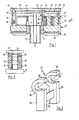
- FIG. 1 comprises a circular disk-shaped yoke plate, generally designated 10, with a central recess 12 into which a tubular central extension 14 of a disk-shaped heat sink 16 engages, on which the yoke plate 10 is fastened and which is attached to the yoke plate 10 opposite side fins 18 carries.
- a schematically indicated mouthpiece or guide piece 17 for guiding printing needles 19 is held in the attachment 14.
- the yoke plate 10 On its side facing away from the heat sink 16, the yoke plate 10 carries a plurality of folding armature magnets 20 in a circular arrangement around the central recess 12
- the radially inner yoke leg 22 each carries a magnet coil 26.
- the magnetic circuit is closed by an essentially radially directed hinged armature 28, to the inner end of which the pressure needle 19 is fastened.
- the hinged armature 28 carries a cylindrical pin 30 which is mounted in a bearing part, generally designated 32, which is fastened to the radially outer yoke leg 24 and is explained in more detail with reference to FIGS. 2 and 3.
- the hinged anchor 28 can thus be pivoted about the axis of the cylindrical pin 30 between the pressure position near the yoke leg shown in FIG. 1 and a position remote from the yoke leg, into which it is fastened by means of a screw compression spring 34 is tensioned and in which it rests on an annular stop 36.
- the helical compression spring 34 is supported at one end on a pin 38 formed in one piece with the yoke plate. At its end facing the hinged anchor 28, the helical compression spring 34 carries a ball 40 which engages in a hemispherical recess 42 on the underside of the hinged anchor 28 so as to reduce the friction between the spring 34 and the hinged anchor 28.
- the stop 36 carries on its side facing the hinged anchors 28 a ring 44 made of a material which dampens the impact of the hinged anchors, in order to prevent the hinged anchors 28 from rebounding from the stop 36.
- the annular disk-shaped stop 36 can be fastened to the yoke plate 10 with the aid of screws 46 which engage in threaded bores 48 which are provided in extensions 50 formed in one piece with the yoke plate 10. With the aid of the spacer sleeves 52 surrounding the screws 46, the distance of the stop 36 from the yoke plate 10 and thus the pivoting path of the hinged armature 28 can be set precisely.
- the bearing part 32 has two storage forks 54 made of plastic, which are connected to one another by a metal web 56 in such a way that they are at a distance from one another which corresponds approximately to the width of the yoke leg 24.
- the metal web 56 is fastened, for example, by spot welding to the radially outward-facing surface of the yoke leg 24, so that the two bearing forks 54 lie on both sides of the yoke leg 24, as can be seen in FIG. 2.
- the bearing forks 54 point radially outwards with their fork opening and close a part zylin between them dharilin between them dharilin between them dharilin between them dharilin between them dharilin between them dharilin between them dharilin between them dharilin between them dharilin between them dharilin between them dharilin between them dharilin between them dharidets 54, which extends slightly over 180 °.
- the opening width of the fork openings is slightly smaller than the diameter of the cylindrical pin 30 fitting into the bearing surfaces 58.
- a printhead with hinged armature magnets designed in this way achieves a long service life with a high-quality print image, does not provide any shadow images even at high working frequencies, and is also suitable for printing on copy sets due to the high achievable impact force of the print needles.
Landscapes
- Impact Printers (AREA)
- Sheet Holders (AREA)
- Paper (AREA)
- Printers Or Recording Devices Using Electromagnetic And Radiation Means (AREA)
Priority Applications (1)
| Application Number | Priority Date | Filing Date | Title |
|---|---|---|---|
| AT88100870T ATE66184T1 (de) | 1987-03-02 | 1988-01-21 | Nadeldruckkopf. |
Applications Claiming Priority (2)
| Application Number | Priority Date | Filing Date | Title |
|---|---|---|---|
| DE3706730 | 1987-03-02 | ||
| DE19873706730 DE3706730A1 (de) | 1987-03-02 | 1987-03-02 | Nadeldruckkopf |
Publications (3)
| Publication Number | Publication Date |
|---|---|
| EP0280864A2 true EP0280864A2 (fr) | 1988-09-07 |
| EP0280864A3 EP0280864A3 (en) | 1989-01-04 |
| EP0280864B1 EP0280864B1 (fr) | 1991-08-14 |
Family
ID=6322132
Family Applications (1)
| Application Number | Title | Priority Date | Filing Date |
|---|---|---|---|
| EP88100870A Expired - Lifetime EP0280864B1 (fr) | 1987-03-02 | 1988-01-21 | Tête d'impression à aiquilles |
Country Status (6)
| Country | Link |
|---|---|
| US (1) | US4838714A (fr) |
| EP (1) | EP0280864B1 (fr) |
| JP (1) | JPS63233849A (fr) |
| AT (1) | ATE66184T1 (fr) |
| DE (2) | DE3706730A1 (fr) |
| ES (1) | ES2024557B3 (fr) |
Cited By (1)
| Publication number | Priority date | Publication date | Assignee | Title |
|---|---|---|---|---|
| US5290112A (en) * | 1989-12-18 | 1994-03-01 | Mannesmann Aktiengesellschaft | Matrix print head, in particular serial matrix pin print head |
Families Citing this family (4)
| Publication number | Priority date | Publication date | Assignee | Title |
|---|---|---|---|---|
| US7314323B2 (en) * | 2003-09-03 | 2008-01-01 | Toshiba Tec Kabushiki Kaisha | Wire dot printer head and wire dot printer |
| JP2005254663A (ja) * | 2004-03-12 | 2005-09-22 | Toshiba Tec Corp | ワイヤドットプリンタヘッド及びワイヤドットプリンタ |
| JP4515121B2 (ja) * | 2004-03-15 | 2010-07-28 | 東芝テック株式会社 | ワイヤドットプリンタヘッド及びワイヤドットプリンタ |
| CN112943824A (zh) * | 2021-04-07 | 2021-06-11 | 浙江弗尔德驱动科技有限公司 | 一体化多点制动重载电梯曳引机的制动器 |
Family Cites Families (24)
| Publication number | Priority date | Publication date | Assignee | Title |
|---|---|---|---|---|
| GB1219019A (en) * | 1968-12-18 | 1971-01-13 | Rootes Motors Ltd | An improved shaft mounting |
| DE2001411B2 (de) * | 1969-02-05 | 1973-05-03 | Aritma, N.P., Prag | Mosaik-drahtdrucker |
| DE2056364B2 (de) * | 1970-11-17 | 1976-05-13 | Offermann, Karl Heinz, 4322 Sprockhövel | Elektromagnetsystem fuer mosaik- druckwerke |
| JPS5516834B2 (fr) * | 1971-11-20 | 1980-05-07 | ||
| US3929214A (en) * | 1974-09-18 | 1975-12-30 | D & D Ass | Wire matrix ballistic impact print head |
| US4167343A (en) * | 1976-09-27 | 1979-09-11 | Golobay Gary L | Print wire actuator mechanism |
| SE404898B (sv) * | 1976-10-11 | 1978-11-06 | Facit Ab | Anordning for punktformig paverkan av ett informationsberande medium |
| DE2717077C3 (de) * | 1977-04-18 | 1980-10-23 | Nixdorf Computer Ag, 4790 Paderborn | Halterung für einen Klappankermagneten eines Mosaikdruckkopfes |
| US4175076A (en) * | 1977-11-21 | 1979-11-20 | Eli Lilly And Company | Azetidinone mercury sulfides and process therefor |
| IL56669A0 (en) * | 1978-02-15 | 1979-05-31 | Nori Sinoto | Matrix printer |
| JPS54152517A (en) * | 1978-05-19 | 1979-11-30 | Mitsubishi Electric Corp | Printer |
| JPS5555717A (en) * | 1978-10-17 | 1980-04-23 | Chuo Kaihatsu Kk | Inserting a self-boring type measurment instrument |
| US4242004A (en) * | 1979-03-21 | 1980-12-30 | Extel Corporation | Dot matrix printhead driver |
| US4320981A (en) * | 1980-03-10 | 1982-03-23 | Data General Corporation | Matrix printhead apparatus |
| JPS56150570A (en) * | 1980-04-24 | 1981-11-21 | Tokyo Electric Co Ltd | Driving device for wire head of dot printer |
| US4349283A (en) * | 1980-09-05 | 1982-09-14 | General Instrument Corporation | Hammer for dot matrix printer |
| US4382701A (en) * | 1981-05-27 | 1983-05-10 | International Computers Ltd. | Wire matrix printing apparatus |
| US4396304A (en) * | 1981-11-24 | 1983-08-02 | International Computers Limited | Print head and drive circuit |
| DE3321301A1 (de) * | 1983-06-13 | 1984-12-13 | Montblanc-Simplo Gmbh, 2000 Hamburg | Tintenversorgungssystem fuer mit fluessiger tinte arbeitende schreibgeraete |
| US4652158A (en) * | 1983-06-17 | 1987-03-24 | Brother Kogyo Kabushiki Kaisha | Armature support device for torsion spring print head |
| JPS602375A (ja) * | 1983-06-21 | 1985-01-08 | Tokyo Electric Co Ltd | ワイヤドツトヘツド |
| US4653943A (en) * | 1984-03-27 | 1987-03-31 | Brother Kogyo Kabushiki Kaisha | Print head |
| JPS61118265A (ja) * | 1984-11-14 | 1986-06-05 | Brother Ind Ltd | ドツトプリンタ−の印字ヘツド |
| JPS61268458A (ja) * | 1985-05-23 | 1986-11-27 | Seikosha Co Ltd | プリンタヘツド |
-
1987
- 1987-03-02 DE DE19873706730 patent/DE3706730A1/de active Granted
-
1988
- 1988-01-21 EP EP88100870A patent/EP0280864B1/fr not_active Expired - Lifetime
- 1988-01-21 AT AT88100870T patent/ATE66184T1/de active
- 1988-01-21 ES ES88100870T patent/ES2024557B3/es not_active Expired - Lifetime
- 1988-01-21 DE DE8888100870T patent/DE3864161D1/de not_active Expired - Lifetime
- 1988-02-17 US US07/156,833 patent/US4838714A/en not_active Expired - Fee Related
- 1988-03-02 JP JP63049462A patent/JPS63233849A/ja active Pending
Cited By (1)
| Publication number | Priority date | Publication date | Assignee | Title |
|---|---|---|---|---|
| US5290112A (en) * | 1989-12-18 | 1994-03-01 | Mannesmann Aktiengesellschaft | Matrix print head, in particular serial matrix pin print head |
Also Published As
| Publication number | Publication date |
|---|---|
| DE3864161D1 (de) | 1991-09-19 |
| EP0280864B1 (fr) | 1991-08-14 |
| US4838714A (en) | 1989-06-13 |
| DE3706730A1 (de) | 1988-09-15 |
| JPS63233849A (ja) | 1988-09-29 |
| ATE66184T1 (de) | 1991-08-15 |
| EP0280864A3 (en) | 1989-01-04 |
| DE3706730C2 (fr) | 1990-04-05 |
| ES2024557B3 (es) | 1992-03-01 |
Similar Documents
| Publication | Publication Date | Title |
|---|---|---|
| DE2630931C3 (de) | Antriebseinrichtung für einen Nadeldrucker | |
| DE3829676A1 (de) | Tauchankermagnet, sowie dessen verwendung als druckhammer in einer druckhammervorrichtung | |
| EP0357860B1 (fr) | Tête d'impression à matrice d'aiguilles du type à armature battante | |
| DE2927415C2 (de) | Mosaikdrucker | |
| DE2119415A1 (de) | Elektromagnetischer antrieb fuer die nadel eines nadeldruckers | |
| DE2910859A1 (de) | Druckkopf fuer einen rasterdrucker | |
| EP0280864B1 (fr) | Tête d'impression à aiquilles | |
| EP0136592A1 (fr) | Relais électromagnétique | |
| DE2629267C3 (de) | Betätigungsvorrichtung fur einen Draht-Matrixdrucker | |
| DE2943440C2 (de) | Klappankermagnet | |
| CH639899A5 (de) | Aufschlagdrucker. | |
| DE2717077C3 (de) | Halterung für einen Klappankermagneten eines Mosaikdruckkopfes | |
| DE2809428A1 (de) | Druckvorrichtung | |
| DE1033091B (de) | Vibrationsmotor fuer Trockenrasiergeraete | |
| CH619820A5 (fr) | ||
| DE2807337A1 (de) | Matrixdruckerkopf | |
| DE2954141C2 (fr) | ||
| DE102018126159A1 (de) | Ventilanordnung und verbrennungskraftmaschine mit einem solchen ventil | |
| EP0157014B1 (fr) | Tête d'impression à aiguilles | |
| DE4320831C1 (de) | Ankerlagerung für ein Klappankerrelais | |
| DE2746601C2 (de) | Klemmvorrichtung zum Verbinden einer Drucknadel mit einem hülsenförmigen Magnetanker | |
| DE3202976C2 (de) | Anordnung für eine verschleißkompensierende Betätigung von Drucknadeln eines Nadeldruckkopfes | |
| DE2457741C2 (de) | Aufbau und Lagerung eines Registrierelementes einer elektrographischen Registriervorrichtung | |
| DE909948C (de) | Relais fuer Fernmelde-, insbesondere Fernsprechanlagen | |
| DD142316A1 (de) | Druckmagneteinheit fuer den typendruck in seriendruckwerken |
Legal Events
| Date | Code | Title | Description |
|---|---|---|---|
| PUAI | Public reference made under article 153(3) epc to a published international application that has entered the european phase |
Free format text: ORIGINAL CODE: 0009012 |
|
| AK | Designated contracting states |
Kind code of ref document: A2 Designated state(s): AT BE CH DE ES FR GB GR IT LI LU NL SE |
|
| PUAL | Search report despatched |
Free format text: ORIGINAL CODE: 0009013 |
|
| AK | Designated contracting states |
Kind code of ref document: A3 Designated state(s): AT BE CH DE ES FR GB GR IT LI LU NL SE |
|
| 17P | Request for examination filed |
Effective date: 19890201 |
|
| 17Q | First examination report despatched |
Effective date: 19900720 |
|
| RAP3 | Party data changed (applicant data changed or rights of an application transferred) |
Owner name: SIEMENS NIXDORF INFORMATIONSSYSTEME AKTIENGESELLSC |
|
| GRAA | (expected) grant |
Free format text: ORIGINAL CODE: 0009210 |
|
| AK | Designated contracting states |
Kind code of ref document: B1 Designated state(s): AT BE CH DE ES FR GB GR IT LI LU NL SE |
|
| PG25 | Lapsed in a contracting state [announced via postgrant information from national office to epo] |
Ref country code: GR Free format text: LAPSE BECAUSE OF FAILURE TO SUBMIT A TRANSLATION OF THE DESCRIPTION OR TO PAY THE FEE WITHIN THE PRESCRIBED TIME-LIMIT Effective date: 19910814 Ref country code: BE Effective date: 19910814 |
|
| REF | Corresponds to: |
Ref document number: 66184 Country of ref document: AT Date of ref document: 19910815 Kind code of ref document: T |
|
| REF | Corresponds to: |
Ref document number: 3864161 Country of ref document: DE Date of ref document: 19910919 |
|
| GBT | Gb: translation of ep patent filed (gb section 77(6)(a)/1977) | ||
| ITF | It: translation for a ep patent filed | ||
| ET | Fr: translation filed | ||
| PG25 | Lapsed in a contracting state [announced via postgrant information from national office to epo] |
Ref country code: DE Effective date: 19911202 |
|
| PG25 | Lapsed in a contracting state [announced via postgrant information from national office to epo] |
Ref country code: AT Effective date: 19920121 |
|
| PG25 | Lapsed in a contracting state [announced via postgrant information from national office to epo] |
Ref country code: LU Free format text: LAPSE BECAUSE OF NON-PAYMENT OF DUE FEES Effective date: 19920131 Ref country code: LI Effective date: 19920131 Ref country code: CH Effective date: 19920131 |
|
| REG | Reference to a national code |
Ref country code: ES Ref legal event code: FG2A Ref document number: 2024557 Country of ref document: ES Kind code of ref document: B3 |
|
| PLBE | No opposition filed within time limit |
Free format text: ORIGINAL CODE: 0009261 |
|
| STAA | Information on the status of an ep patent application or granted ep patent |
Free format text: STATUS: NO OPPOSITION FILED WITHIN TIME LIMIT |
|
| 26N | No opposition filed | ||
| REG | Reference to a national code |
Ref country code: CH Ref legal event code: PL |
|
| PGFP | Annual fee paid to national office [announced via postgrant information from national office to epo] |
Ref country code: SE Payment date: 19930119 Year of fee payment: 6 |
|
| PGFP | Annual fee paid to national office [announced via postgrant information from national office to epo] |
Ref country code: NL Payment date: 19930131 Year of fee payment: 6 |
|
| PG25 | Lapsed in a contracting state [announced via postgrant information from national office to epo] |
Ref country code: SE Effective date: 19940122 |
|
| PG25 | Lapsed in a contracting state [announced via postgrant information from national office to epo] |
Ref country code: NL Effective date: 19940801 |
|
| NLV4 | Nl: lapsed or anulled due to non-payment of the annual fee | ||
| PGFP | Annual fee paid to national office [announced via postgrant information from national office to epo] |
Ref country code: FR Payment date: 19950116 Year of fee payment: 8 |
|
| EUG | Se: european patent has lapsed |
Ref document number: 88100870.0 Effective date: 19940810 |
|
| PGFP | Annual fee paid to national office [announced via postgrant information from national office to epo] |
Ref country code: GB Payment date: 19951218 Year of fee payment: 9 |
|
| PG25 | Lapsed in a contracting state [announced via postgrant information from national office to epo] |
Ref country code: FR Effective date: 19960930 |
|
| REG | Reference to a national code |
Ref country code: FR Ref legal event code: ST |
|
| PG25 | Lapsed in a contracting state [announced via postgrant information from national office to epo] |
Ref country code: GB Effective date: 19970121 |
|
| PGFP | Annual fee paid to national office [announced via postgrant information from national office to epo] |
Ref country code: ES Payment date: 19970131 Year of fee payment: 10 |
|
| GBPC | Gb: european patent ceased through non-payment of renewal fee |
Effective date: 19970121 |
|
| PG25 | Lapsed in a contracting state [announced via postgrant information from national office to epo] |
Ref country code: ES Free format text: THE PATENT HAS BEEN ANNULLED BY A DECISION OF A NATIONAL AUTHORITY Effective date: 19980122 |
|
| REG | Reference to a national code |
Ref country code: ES Ref legal event code: FD2A Effective date: 20020204 |
|
| PG25 | Lapsed in a contracting state [announced via postgrant information from national office to epo] |
Ref country code: IT Free format text: LAPSE BECAUSE OF NON-PAYMENT OF DUE FEES;WARNING: LAPSES OF ITALIAN PATENTS WITH EFFECTIVE DATE BEFORE 2007 MAY HAVE OCCURRED AT ANY TIME BEFORE 2007. THE CORRECT EFFECTIVE DATE MAY BE DIFFERENT FROM THE ONE RECORDED. Effective date: 20050121 |